Engineering summary: Cable attenuation measures signal power loss per unit length—expressed in dB/100 m for metallic pairs and coax, or dB/km for optical fibres—as high-frequency energy dissipates into conductor skin resistance and insulation dielectric heating. On crane reels, drag chains, and mining runs exceeding 70–100 m, integrating buffered optical fibres inside composite cables eliminates packet loss and VFD noise.
Automated ship-to-shore (STS) cranes, rail-mounted gantry (RMG) yards, tunnel boring machines (TBMs), and remotely operated subsea vehicles (ROVs) now push real-time LiDAR, HD camera streams, and safety-PLC PROFINET traffic alongside multi-megawatt variable-frequency drive (VFD) power. When commissioning teams apply office-grade copper Ethernet distance rules to moving industrial cables, unexpected attenuation spikes trigger intermittent safety trips that are nearly impossible to diagnose with a basic DC multimeter.
What Are Cable Attenuation and Mean Attenuation, and How Are They Calculated?
Cable attenuation (α) is the logarithmic ratio of transmitted input power to received output power along a matched transmission line, measured in decibels (dB). Every 3 dB of attenuation halves signal power, while 20 dB reduces power by 99% (and signal voltage amplitude by 90%). Mean attenuation represents the average insertion loss across multiple cores, pairs, or test wavelengths.
For a transmission line terminated at its characteristic impedance Z0 (such as 100 Ω for industrial Ethernet, 120 Ω for RS-485/CANbus, or 50 Ω for RF coaxial tow cables), total link attenuation combines cable length loss with connector, splice, and rotary-joint insertion losses:
- Decibel loss definition:
α (dB) = 10 · log10(Pin / Pout) = 20 · log10(Vin / Vout) - End-to-end link budget:
Ltotal (dB) = α0 × (L / 100) + Nconn·Lconn + Nsplice·Lsplice + LFORJ + Maging - Mean attenuation (αmean) on factory test reports:
αmean = (1 / N) × Σαi, used on OTDR drum acceptance certificates and multi-pair crosstalk/loss sweeps to verify uniform core manufacturing—though link engineering must always design to worst-case maximum attenuation, never the mean alone.
In metallic copper cables, high-frequency attenuation follows αCu(f) ≈ k1·√f + k2·f, where k1·√f comes from AC conductor skin-effect resistance and k2·f comes from dielectric dissipation (tan δ) in the insulation. For low-frequency 50/60/400 Hz power voltage drop mechanics, compare our cable resistance vs impedance guide.
Copper Twisted-Pair vs Coaxial vs Optical Fibre Attenuation Comparison Table
Fine-stranded flexible copper data cables exhibit 20% to 50% higher specific attenuation (dB/100 m) than solid building wire because multi-wire contact interfaces and tinned coatings elevate high-frequency skin resistance. Optical fibres reduce signal loss by nearly two orders of magnitude—dropping from ~28 dB per 100 meters in stranded Cat5e/Cat6A copper down to 0.035 dB per 100 meters in single-mode glass.
| Industrial Transmission Medium | Test Frequency / Wavelength | Typical Attenuation (dB/100 m) | Equivalent Loss per km (dB/km) | Practical Unrepeated Dynamic Run | Representative TEBAOFLEX Series |
|---|---|---|---|---|---|
| Screened Instrumentation Pair (0.75–1.5 mm², OS / IS+OS) | 1.2 kHz (HART) / 1 MHz (Fieldbus) | 0.08 dB (HART) / 1.1–1.8 dB (1 MHz) | 0.8–18 dB/km | 800–1,200 m (4–20 mA / low-baud RS-485) | PE/PVC Screened Instrumentation |
| Solid Horizontal Cat5e / Cat6 Copper (Static Reference) | 100 MHz | 19.8–22.0 dB/100 m | 198–220 dB/km | 90 m permanent link (static building tray only; fails if flexed) | Static reference only |
| Flexible Stranded PUR Drag-Chain / Reeling Data (AWG 22/7–26/19) | 100 MHz (PROFINET / EtherCAT) | 24.5–32.0 dB/100 m | 245–320 dB/km | 60–75 m max (derated by 1.2×–1.5× stranding factor) | S 368 C Drag-Chain Data, RP-D PROFINET Drum |
| Double-Armoured Subsea Coaxial Tow Cable (50 Ω Foam PE) | 100 MHz / 400 MHz | 4.2 dB / 8.8 dB per 100 m | 42–88 dB/km | 300–1,000 m (sonar & analog/RF subsea telemetry) | 50 Ω Coax Armoured Tow Cable |
| Multi-Mode Optical Fibre (OM3 / OM4, 50/125 µm) | 850 nm / 1300 nm | 0.30–0.35 dB / 0.10–0.15 dB | ≤3.5 dB/km / ≤1.5 dB/km | 300–550 m (10GBASE-SR crane & spreader telemetry) | Rubber Crane FO, SYSLTOE-J FO |
| Single-Mode Bend-Insensitive Fibre (G.657.A1 / G.652.D, 9/125 µm) | 1310 nm / 1550 nm | 0.035–0.040 dB / 0.022–0.025 dB | ≤0.40 dB/km / ≤0.25 dB/km | 2,000–10,000+ m (port runways, TBMs, subsea ROVs) | (N)TSCGEWÖU-SR FO, ROV Umbilical |
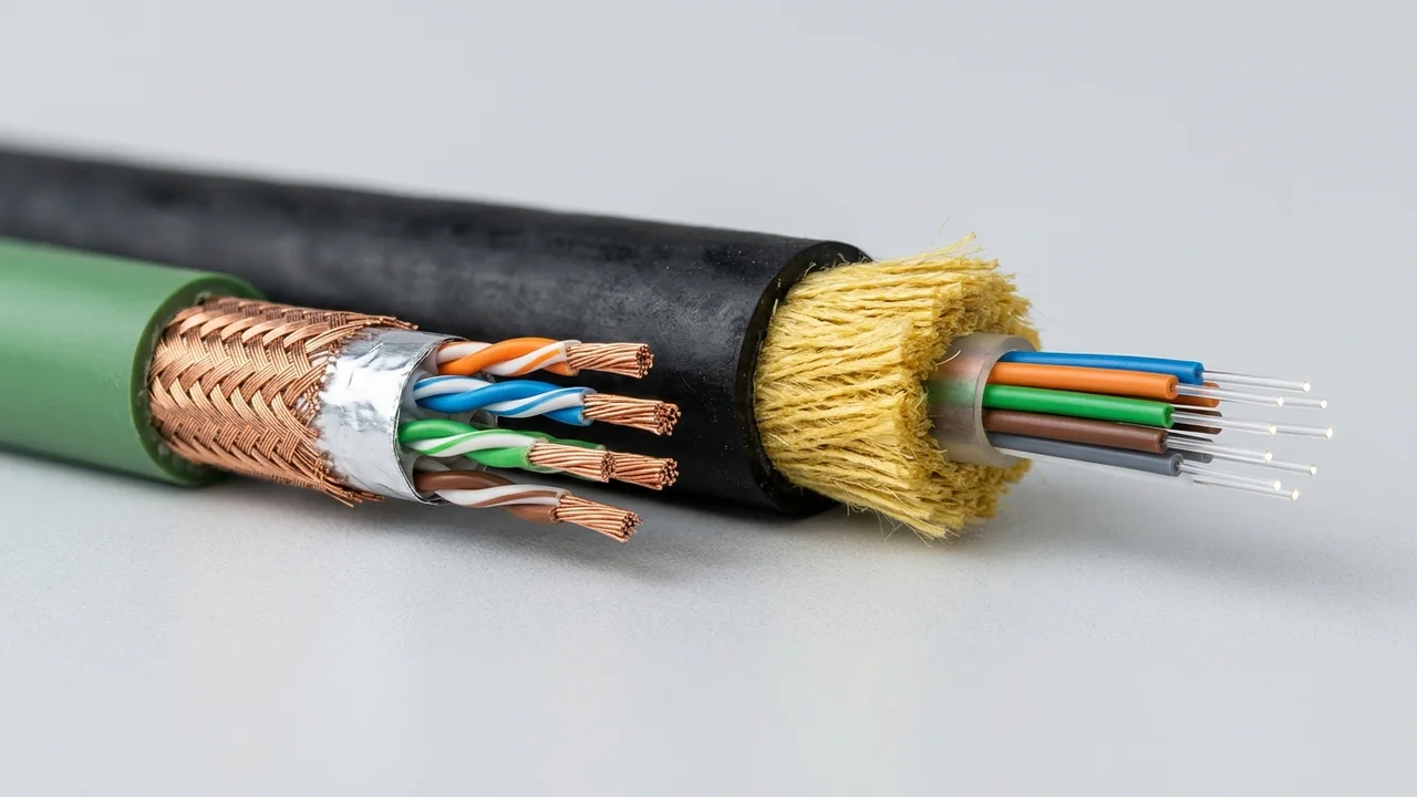
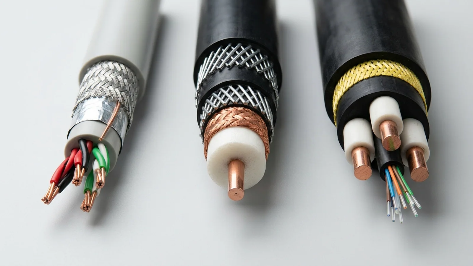
Media Physics: Stranded Copper Pairs vs. Buffered Optical Fibre Core
- Stranded Copper Drag-Chain Core (Left): Tinned fine strands survive millions of flex cycles inside PUR + foil/braid shielding, but elevated RF skin resistance caps 100 MHz PROFINET travel at ~60–75 m.
- Aramid-Buffered Optical Fibre Module (Right): Loose-tube buffered 9/125 µm or 50/125 µm glass fibres decouple tensile strain via aramid yarns while cutting attenuation below 0.4 dB/km with zero EMI pickup.
Optical cores inside reeling cables use optimized helix lay angles so drum tension stretches the elastomer bed rather than the glass fibre.
Why Do Dynamic Bending, Water Ingress, and VFD Harmonics Spike Attenuation in the Field?
Static bench attenuation figures assume dry, unstrained cable laid straight at 20 °C. On operating industrial machinery, four physical mechanisms add 3 dB to 15+ dB of dynamic loss over time: insulation compression changing characteristic impedance, moisture ingress multiplying dielectric permittivity, optical microbending/macrobending under drum tension, and VFD electromagnetic noise collapsing signal-to-noise margin.
Why moisture ruins high-frequency copper cables instantly: Dry foamed polyethylene (PE) data insulation has a relative permittivity (ϵr) of ~1.45–2.3, whereas liquid water has ϵr ≈ 80. Even microscopic jacket pinholes in flooded crane trenches soak inner braids, detuning pair impedance from 100 Ω to <65 Ω and spiking return loss and attenuation long before any DC short-circuit appears.
- Copper pair untwisting & radial crushing: Multi-layer random reeling drums exert high radial pressure on bottom cable wraps, flattening soft foam-PE data pairs and creating periodic impedance reflections (structural return loss).
- Optical macrobending vs. microbending: Macrobending occurs when an optical jumper is bent tighter than its critical radius (causing 1550 nm light modes to leak out of the cladding—why ITU-T G.657.A1/A2 bend-insensitive single-mode fibres are preferred over legacy G.652.D inside compact junction boxes). Microbending occurs inside poorly buffered composite cables when rough copper power cores press microscopically against the fibre tube under 15–25 N/mm² reeling pull.
- Rotary collector & FORJ budget: Motorized crane drums pass optical signals through a Fibre Optic Rotary Joint (FORJ), which typically adds
0.5 dB to 2.0 dBof rotational insertion loss per pass—a fixed budget term that must be included alongside LC/SC bulkhead adapters (~0.3–0.5 dBper mated pair).
When Should You Switch from Copper Data Cores to Hybrid Fibre-Optic Reeling Cables?
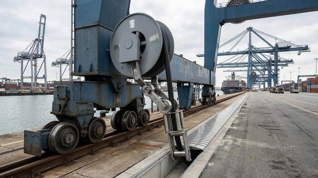
Upgrade from copper data pairs to an integrated power-plus-fibre-optic composite cable whenever dynamic cable travel exceeds 65 meters for 100 Mbps/1 Gbps industrial Ethernet, whenever medium-voltage (3.6/6 kV to 20/35 kV) power phases share the same drum or spreader basket, or whenever multi-camera crane automation demands gigabit bandwidth without adding a second cable reel.
TEBAOFLEX engineers dedicated strain-decoupled optical fibre elements (6, 12, 18, or 24 fibres in single-mode 9/125 µm, multi-mode 50/125 µm, or mixed SM+MM hybrid tubes) directly into the interstitial lay of both low-voltage and medium-voltage dynamic cables. Explore our complete industrial cable classification guide and port crane reeling cable selection guide, or match your equipment to these proven series:
- Medium-Voltage STS, RMG & Shore-Power Drums: Specify (N)TSCGEWÖU-SR FO, R-(N)TSCGEWÖU FO (3.6/6–20/35 kV), or (N)TSCGEW11Y 6/10 kV PUR shore-power FO.
- Vertical Spreader Gravity Baskets & Crane Trolleys: Deploy aramid-reinforced SYSLTOE-J FO 0.6/1 kV spreader basket cables, FESTOON PUR FO trolley cables, or dedicated all-fibre Rubber Crane FO reeling cables.
- Short-Stroke (<65 m) Robotics & Spring/Motorized LV Drums: Where copper RJ45/M12 termination simplicity outweighs distance, use double-shielded S 368 C PUR drag-chain data cables or RP-D 0.6/1 kV PROFINET drum cables.
Frequently Asked Questions
Why is my flexible drag-chain or reeling Ethernet cable limited to 65 meters instead of 100 meters?
The familiar 100-meter Ethernet rule assumes 90 meters of solid 23/24 AWG horizontal copper wire (~19.8 dB/100 m @ 100 MHz). Flexible reeling and drag-chain data cables use fine-stranded 24/7 or 26/19 tinned copper to resist fatigue, which raises specific attenuation by 20% to 50% (~25–32 dB/100 m), hitting the 21 dB channel insertion-loss limit at 60 to 75 meters.
What is the difference between 850 nm multi-mode and 1310/1550 nm single-mode attenuation in reeling cables?
Multi-mode 50/125 µm (OM3/OM4) fibres exhibit ≤3.0–3.5 dB/km at 850 nm and suit 100–500 m crane or spreader links using rugged optical transceivers. Single-mode 9/125 µm (ITU-T G.657.A1) fibres achieve ≤0.40 dB/km at 1310 nm and ≤0.25 dB/km at 1550 nm, supporting multi-kilometer TBM, mining conveyor, and ROV tethers.
Why does 1550 nm show higher loss than 1310 nm when an optical reeling cable is pinched or over-bent?
In dry unstrained single-mode glass, intrinsic Rayleigh scattering is lower at 1550 nm (~0.22 dB/km) than at 1310 nm (~0.35 dB/km). However, longer 1550 nm wavelengths are less tightly confined to the 9 µm core, so if an OTDR test reveals noticeably higher loss at 1550 nm than at 1310 nm at a specific footage mark, it pinpoints a mechanical pinch, tight bend, or crushed buffer tube.
Does TEBAOFLEX perform factory OTDR attenuation testing on composite fibre-optic reeling cables?
Yes. Every drum of TEBAOFLEX fibre-optic and composite power-plus-fibre reeling cable undergoes 100% factory OTDR trace verification at dual wavelengths (850/1300 nm for multi-mode or 1310/1550 nm for single-mode) alongside HV spark and dielectric withstand testing on the power cores before export shipment.
Eliminate Dynamic Signal Loss on Crane, Mining & Subsea Equipment
Whether you are retrofitting an automated STS/RMG port crane, extending a TBM tunneling feeder beyond 1,000 meters, or specifying screened industrial instrumentation cables, TEBAOFLEX engineers custom copper, coaxial, and composite fibre-optic cables built for continuous mechanical stress.
- Share your protocol (PROFINET, EtherCAT, Gigabit Ethernet, RS-485, or 4–20 mA), travel distance, and optical transceiver budget.
- Specify single-mode (9/125 µm G.657.A1), multi-mode (50/125 µm OM3/OM4, 62.5/125 µm), or mixed fibre counts alongside LV/MV power cores.
- Receive full factory datasheet parameters including dB/km attenuation limits, maximum tensile load (N), and minimum dynamic drum radius.
Standards & technical references: IEC 60793-2 & IEC 60794 (Optical fibres and optical fibre cables); ITU-T G.652.D & G.657.A1/A2 (Single-mode bend-insensitive optical fibre characteristics); ISO/IEC 11801 & IEC 61156-6 (Stranded work-area and drag-chain balanced data cables); DIN VDE 0250-813 (Medium-voltage flexible trailing and reeling cables with integrated optical elements).