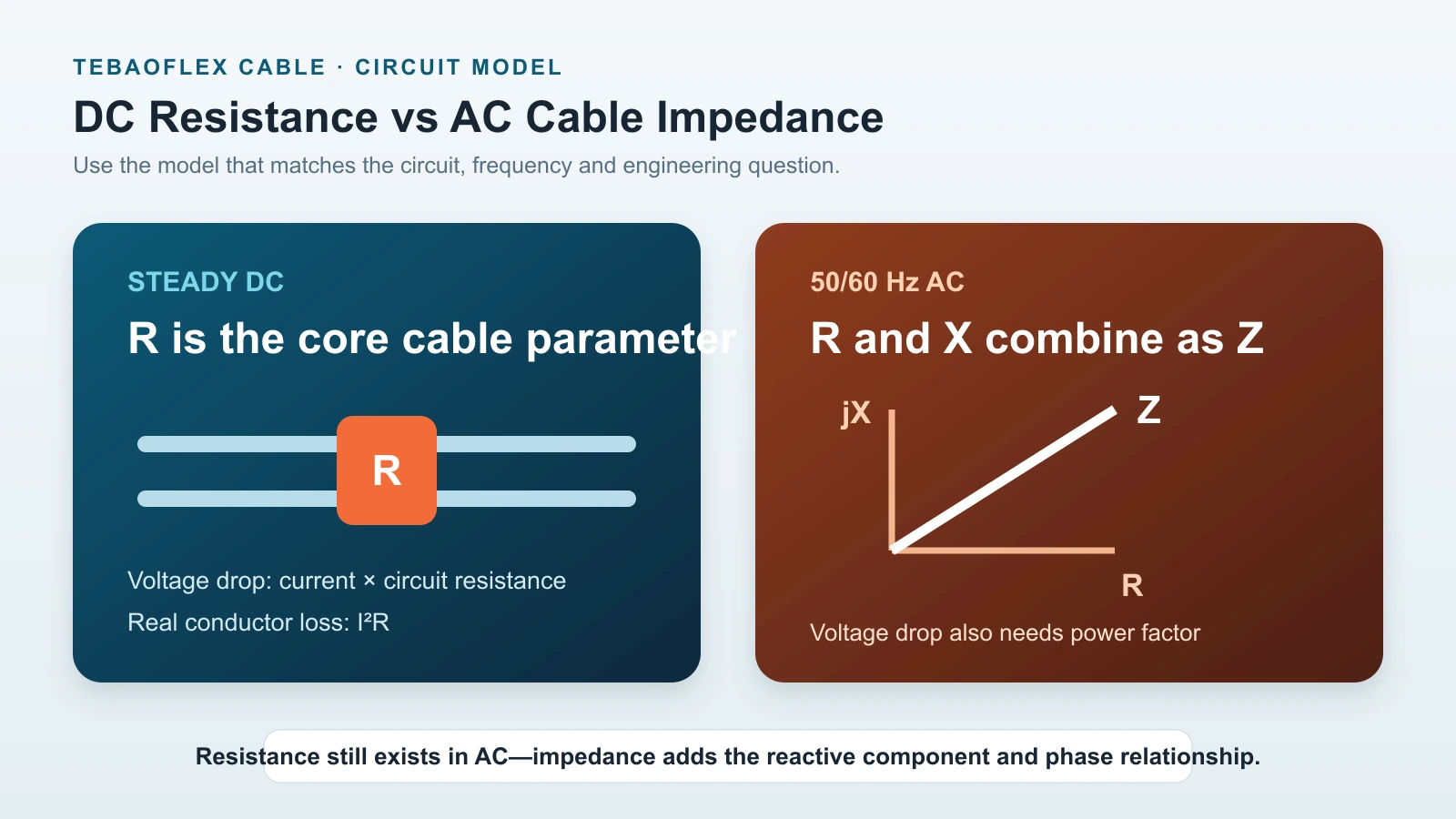
Cable resistance vs impedance is a practical distinction in AC power engineering. Resistance describes the real component that produces conductor heating and I²R loss. Impedance is the broader AC quantity that combines resistance with reactance and preserves the phase relationship between them.
In a basic steady-DC calculation, conductor resistance may be the dominant electrical parameter. In a 50/60 Hz feeder, motor circuit or medium-voltage system, engineers may also need cable reactance and impedance for voltage-drop, fault-current and system studies. Variable-frequency drives add a further layer: fast switching, cable capacitance, EMC and wave propagation mean that a simple 50/60 Hz R + X calculation cannot describe every drive-cable phenomenon.
| Parameter | Steady DC | 50/60 Hz AC | VFD / fast switching |
|---|---|---|---|
| Resistance R | Important | Important | Important |
| Reactance X | Not normally used in steady-state cable sizing | Important | Frequency-dependent |
| Series impedance Z | Not normally required for basic DC sizing | Important | Only part of the picture |
| Cable capacitance | Limited relevance in a basic DC model | Can matter for long or MV cable | Often important |
| Power factor | Not applied in the same way | Important | Drive-system specific |
| EMC and screening | Application-dependent | Application-dependent | Often critical |
| Characteristic impedance | Usually irrelevant | Usually not central to feeder sizing | Can matter in reflected-wave analysis |
Resistance vs Impedance: What Is the Difference?
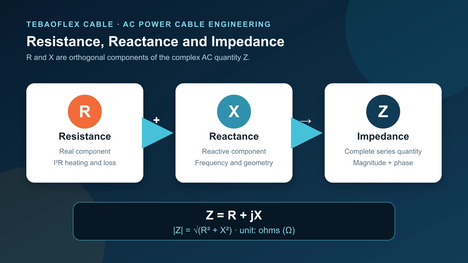
Resistance R is the real opposition to current flow. It exists in DC and AC conductors and converts electrical energy into heat. Reactance X represents AC opposition associated with electric or magnetic field energy storage. Impedance Z combines the two as a complex quantity.
| Property | Resistance R | Reactance X | Impedance Z |
|---|---|---|---|
| Main relevance | DC and AC conductor loss | AC circuit behaviour | Overall AC series behaviour |
| Unit | Ω | Ω | Ω |
| Real heat loss | Yes | Ideal reactance does not represent continuous real-power dissipation | Includes both the real and reactive components |
| Frequency dependence | AC resistance can vary with frequency | Yes | Yes |
| Typical cable use | I²R loss and DC drop | AC voltage drop and network analysis | AC system and fault calculations |
Resistance is part of impedance; impedance is not another word for resistance.
What Is Cable Resistance R?
For a uniform conductor, the simplified relationship is R = ρL/A. Resistivity ρ depends on conductor material, L is conductor length and A is cross-sectional area. Temperature, stranding and manufacturing tolerances also affect the finished conductor. Our full cable resistance formula guide explains these inputs and the difference between a theoretical estimate and a specified maximum resistance.
Cable data commonly state DC resistance at 20°C in Ω/km. That reference value is useful, but a cable operating under load can be hotter, and the resistance of copper or aluminium normally increases with temperature. IEC 60228:2023 includes conductor resistance requirements and informative temperature-correction factors for measurement. The official IEC 60228 scope confirms that the standard covers solid, stranded, Milliken and flexible conductors within its stated range.
DC resistance vs AC resistance
Resistance does not disappear in AC. Instead, the effective AC resistance can be higher than the DC resistance because current distribution changes. Skin effect tends to concentrate current nearer the conductor surface, while proximity effect changes current distribution in response to nearby conductors. The difference depends on frequency, conductor size and construction, spacing and metallic surroundings.
The general relationship is therefore RAC ≥ RDC for the same reference conditions, but the size of the difference must come from an appropriate calculation or cable data. IEC 60287-1-1:2023 provides formulae for steady-state cable current ratings and losses for its scope; it should not be replaced by an assumed universal AC correction factor. See the IEC 60287-1-1 scope for the standard’s stated application.
What Is Cable Reactance X?
Reactance is the AC opposition associated with electric and magnetic field energy storage. In ordinary power-cable series-impedance discussions, inductive reactance is usually the main X term:
XL = 2πfL
Here, f is frequency and L is inductance. The formula shows why inductive reactance is frequency-dependent. A cable has inductance even though no separate coil is installed: current in each conductor creates a magnetic field, and the geometry of the complete circuit affects that field.
Cable reactance can therefore depend on conductor spacing, core arrangement, single-core or multicore construction, trefoil or flat formation, metallic screens and sheaths, bonding, and frequency. Resistance responds strongly to conductor material and area; reactance is often more sensitive to electromagnetic geometry.
What about cable capacitance?
Conductors separated by insulation form capacitance between phases and between conductor and screen or earth. Capacitance can become significant in long medium-voltage cables and drive systems. A complete cable model can include series R and L plus shunt capacitance and dielectric effects. This article keeps the basic 50/60 Hz series discussion focused on R + jX, while treating VFD behaviour separately.
What Is Cable Impedance Z?
Cable series impedance is written as:
Z = R + jX
The imaginary operator j keeps the reactive component at right angles to the real component. This matters because resistance is associated with real-power dissipation while reactance changes the voltage-current phase relationship. Their ordinary numerical sum would lose that information.
The impedance magnitude is:
|Z| = √(R² + X²)
The impedance phase angle can be expressed as θ = tan−1(X/R). As the X/R ratio increases, the reactive component becomes more significant. Engineers still need the separate R and X values for many practical calculations; magnitude alone is not a universal replacement.
Cable R, X and Z Example
Assume a cable manufacturer gives the following series data at a stated frequency and temperature:
- R = 0.30 Ω/km
- X = 0.08 Ω/km
The complex impedance per kilometre is:
Z = 0.30 + j0.08 Ω/km
Its magnitude is approximately:
|Z| = √(0.30² + 0.08²) ≈ 0.31 Ω/km
For a 100 m route, or 0.1 km, the per-phase values for that cable section are R = 0.03 Ω and X = 0.008 Ω. These numbers do not mean that every AC voltage drop can be calculated as current × 0.031 Ω. Power factor, phase configuration and the separate R/X components still matter.
Which Parameter Should You Use?
| Engineering question | Principal cable data | Additional conditions |
|---|---|---|
| DC voltage drop | Circuit resistance R | Length, conductor temperature and connections |
| Real conductor loss | R in Ploss = I²R | Actual current and operating resistance |
| Conductor heating | AC or DC resistance as applicable | Thermal environment and installation |
| AC voltage drop | R and X | Power factor, length and phase configuration |
| AC series impedance | Z = R + jX | Frequency and geometry |
| Short-circuit current | Total system impedance | Source, transformer, cable, fault type and grounding |
| VFD EMC | More than simple R/X | Screen, termination, grounding, drive and route |
| Reflected-wave analysis | Transmission-line parameters | Drive edge, motor, length and filter |
Why Resistance Alone Is Not Enough for AC Voltage Drop
For an approximate balanced three-phase feeder, a common voltage-drop relationship is:
ΔV = √3 × I × L × (R cosφ + X sinφ)
R and X must use units consistent with length L. The power factor angle φ determines how their contributions project into the voltage-drop result. At power factor near unity, the R term often dominates. As power factor falls for an inductive load, the relative X contribution can increase.
This is why |Z| should not simply replace the full voltage-drop expression. Cable impedance magnitude and AC voltage drop are related but not interchangeable. Use the complete AC cable voltage-drop calculation for single-phase and three-phase circuits.
Resistance Determines Real I²R Power Loss
Real conductor loss is principally calculated with Ploss = I²R, using the appropriate conductor resistance. It is not I²|Z|. An ideal reactance stores energy in a field and returns it; it does not continuously convert all of that reactive component into conductor heat.
Real cables can also have sheath, screen, dielectric and other AC losses depending on construction and voltage. Those effects require the relevant engineering method. The central distinction remains: do not treat reactance as if it were the same quantity as real resistance. The cable I²R power-loss guide covers current, conductor temperature, energy loss and efficiency in detail.
Why Cable Impedance Matters for Fault Current
Prospective fault current depends on source voltage and the total impedance from the source to the fault. Cable impedance is one part of that path; transformer impedance, upstream conductors, generators, motors, connections, grounding and fault type can also contribute. Increasing the path impedance generally reduces prospective current, but protective-device performance must be checked through a complete study.
Balanced operation and three-phase faults commonly use positive-sequence data. Earth-fault studies can require zero-sequence impedance, which is strongly affected by screens, sheaths, armour, bonding and the earth-return path. A single generic “cable impedance” number is therefore not enough for every fault calculation.
How Cable Size, Length and Geometry Affect Impedance
Increasing conductor cross-section lowers resistance substantially because R is approximately inversely proportional to area. Reactance does not normally fall in the same proportion. In large AC conductors, the X/R ratio can therefore become more important even while the total impedance decreases.
For a uniform cable section, both total R and total X rise approximately with route length when their values are stated in Ω/km. Convert the route to kilometres before multiplying. A 100 m section is 0.1 km. The guide to cable length and voltage drop explains one-way length and circuit-path assumptions.
Geometry also matters. Single-core cables in flat formation and trefoil formation can have different inductance, screen/sheath losses and mutual effects. Multicore construction controls conductor spacing internally. Screen and sheath bonding changes return paths and losses. Use data for the actual cable design and installed formation instead of a universal reactance value.
How Frequency Affects Cable Impedance
Inductive reactance follows XL = 2πfL, so the same inductance gives a larger reactance at a higher frequency. AC resistance can also change with frequency because of skin and proximity effects. Total impedance behaviour depends on the cable construction and frequency range; it is unsafe to say that every form of Z always increases in one simple proportion.
50 Hz vs 60 Hz
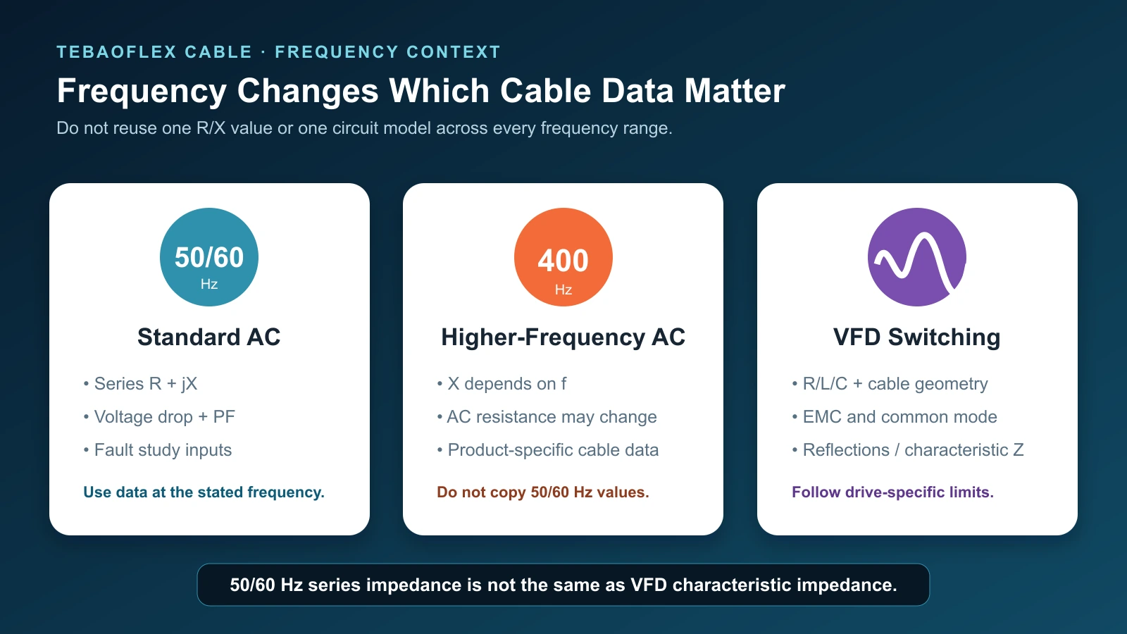
For conventional industrial power systems, 50 Hz and 60 Hz remain power-frequency applications, but reactance is frequency-dependent. Use the frequency stated in the cable or engineering data. Do not silently reuse a 50 Hz X value in a calculation that requires a verified 60 Hz value.
400 Hz cable systems
Aircraft ground-power systems illustrate why frequency belongs in an RFQ. A 400Hz aircraft ground power cable supplies a very different frequency environment from a 50/60 Hz plant feeder. Selection still requires voltage, current, length, conductor schedule, connector interface and handling duty, but the electrical data must also be appropriate to 400 Hz.
Resistance vs Impedance in Motor Circuits
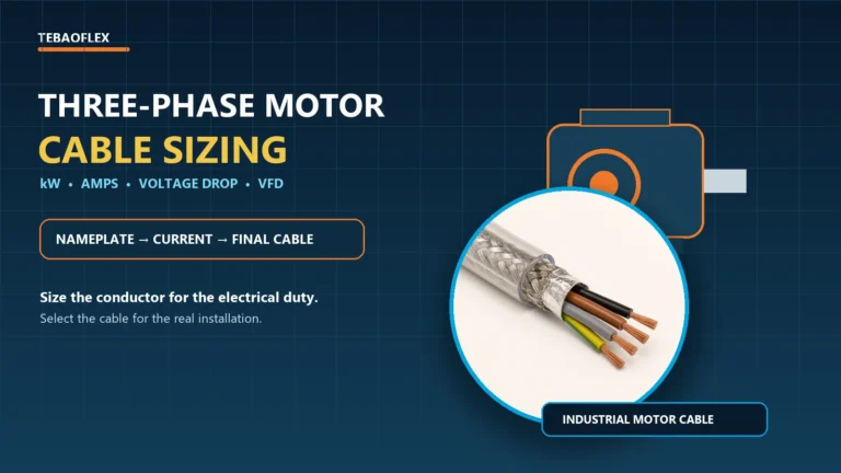
A three-phase motor load has current, power factor and starting behaviour. A cable can pass the continuous ampacity check but create excessive running or starting voltage drop over a long route. The design should consider R, X, power factor, length, installation and protective coordination. Follow the complete three-phase motor cable sizing workflow rather than choosing only from motor kW.
Power factor also affects current for a given real-power demand. Lower power factor can increase line current, which raises I²R loss, while the R cosφ + X sinφ terms change the voltage-drop relationship. Power factor is therefore connected to both cable current and voltage regulation, but it does not change the cable’s physical R or X by itself.
Why VFD Cable Impedance Is More Complicated
VFD cable impedance is not fully described by |Z| = √(R² + X²) at 50/60 Hz. A drive output contains fast switching edges and high-frequency components. Cable capacitance, inductance, characteristic impedance, motor surge impedance, common-mode paths and screen termination can affect current, EMC and voltage at the motor.
Series impedance vs characteristic impedance
Series impedance is normally expressed in Ω/km and used for steady-state voltage drop and network studies. Characteristic impedance is a transmission-line quantity associated with travelling waves. It becomes relevant when the cable is electrically long compared with the rise time of a drive pulse. These are different concepts even though both use the word impedance.
Why VFD motor-cable length matters
Drive pulses travel along the motor cable and can reflect at impedance discontinuities. The importance depends on drive model, switching and rise time, cable type and length, motor, grounding and filters. There is no universal maximum VFD cable length. ABB’s current ACQ80-04 hardware documentation, for example, gives product- and configuration-specific limits and shows that chokes, du/dt filters or sine filters can change permitted lengths. Always follow the selected drive and motor documentation.
Screening and EMC
VFD motor cable selection also needs an EMC strategy. IEC 61800-3:2022 specifies EMC requirements and test methods for adjustable-speed power drive systems and machine tools within its stated scope; the official IEC 61800-3 page notes that the 2025 corrigendum is incorporated. Cable screen conductivity, symmetrical geometry, bonding, route separation and low-impedance termination all influence the installed result.
ABB’s ACS480 hardware manual recommends a symmetrical shielded VFD motor cable for relevant installations and shows 360-degree shield grounding. The correct cable does not compensate for a poor termination.
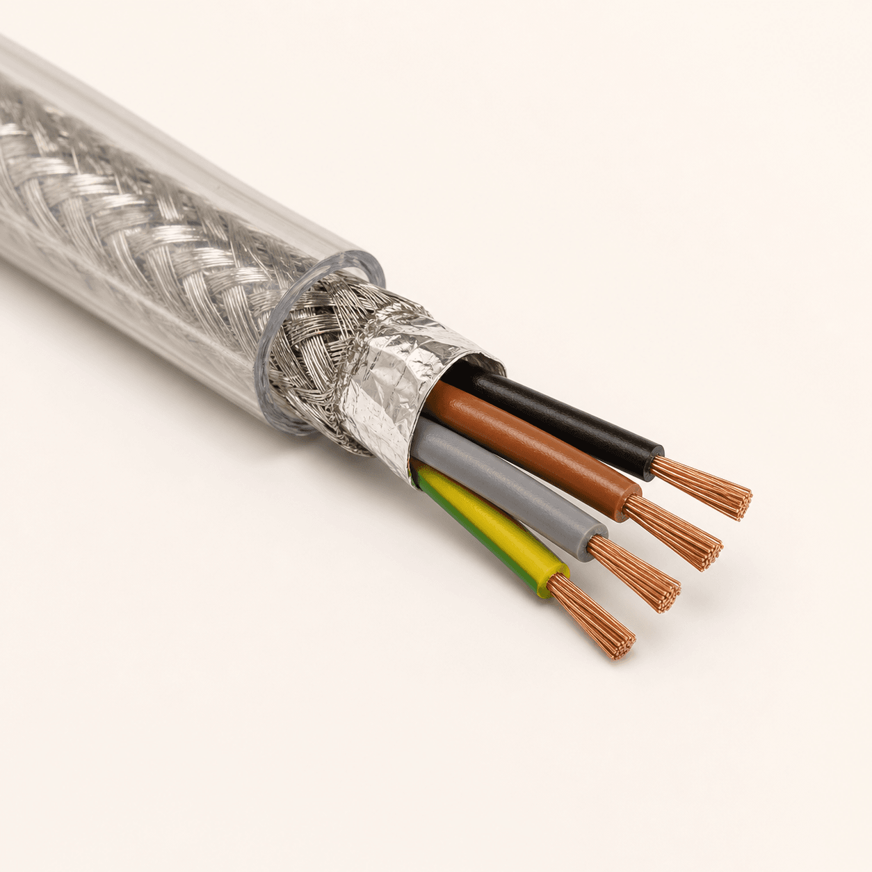
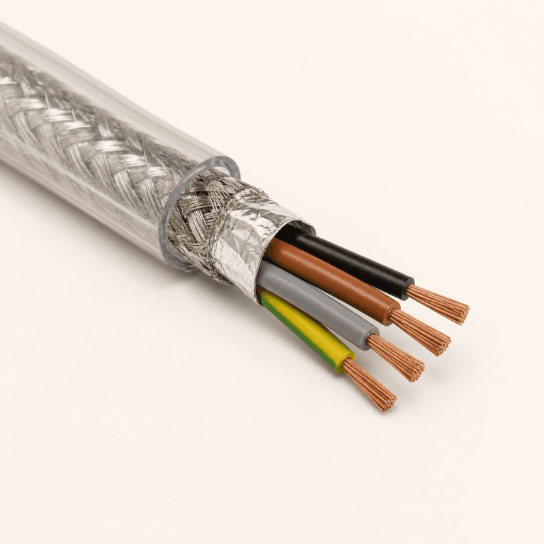
The 2YSLCY-JB shielded VFD motor cable uses Class 5 copper conductors, PE insulation, aluminium foil and a tinned-copper braid beneath a transparent PVC sheath. It is a starting construction for fixed or occasionally moved 0.6/1 kV drive connections—not a universal solution for every drive, route or continuous-motion system.
Medium-Voltage VFD Cable Impedance and EMC
A medium-voltage VFD reeling system combines insulation coordination, drive switching, EMC, cable electrical parameters and repeated mechanical movement. Mining shovels, reclaimers, large pumps and mobile machinery can require all of these factors to be reviewed together.
The (N)TSCGEWOEU EMV FC medium-voltage VFD reeling cable is a 3.6/6 kV to 12/20 kV product family with flexible conductors and an aluminium-foil plus tinned-copper-braid EMC screen. Final selection still depends on voltage class, conductor size, drum, travel speed, bending radius, grounding, termination and drive documentation.
Shielding Does Not Automatically Mean Lower Impedance
A cable screen can serve EMC control, electric-field control, bonding, fault-current return or personnel-safety objectives. Its presence does not prove that the cable has a lower series-impedance magnitude than every unshielded construction. Impedance depends on geometry, frequency, materials and how screens or sheaths are connected.
For that reason, specify the function: EMC screen, metallic sheath, individual conductor screen, overall braid or protective conductor. Then request the parameter needed for the study. A screening percentage alone is not a complete impedance or EMC specification.
Common Cable Resistance vs Impedance Mistakes
- Using resistance and impedance as synonyms. R is the real component of Z; it is not the complete AC quantity.
- Using DC resistance as the only AC cable parameter. This can be an approximation in a limited case, not a universal rule.
- Using |Z| directly as the full voltage-drop formula. AC voltage drop normally needs R, X, power factor and circuit configuration.
- Using I²Z for real conductor heating. Real conductor loss is principally I²R, with additional AC losses treated separately.
- Assuming reactance falls in direct proportion to conductor area. Cable geometry means X does not follow the same 1/A relationship as R.
- Reusing 50 Hz X values at 400 Hz. Electrical parameters must match the stated frequency.
- Treating VFD characteristic impedance as 50/60 Hz series impedance. Reflections require a transmission-line model.
- Ignoring installation arrangement. Single-core spacing, formation, screen bonding and parallel circuits can change study inputs.
When Do You Need Actual Cable Impedance Data?
Request manufacturer or project-specific R/X/Z data for long AC feeders, large conductors, high-current systems, motor starting, short-circuit studies, medium-voltage cables, VFD systems, 400 Hz supplies, parallel cables and special single-core formations. Different studies require different data: voltage drop needs R/X and power factor; earth-fault work can require zero-sequence impedance; VFD analysis may need capacitance, screen data and drive-specific parameters.
| Parameter to request | Typical engineering use |
|---|---|
| DC resistance at 20°C | Conductor reference and compliance comparison |
| AC resistance at stated frequency/temperature | AC loss and voltage-drop study |
| Reactance X | AC voltage drop and network analysis |
| R + jX | Series-impedance model |
| Positive-sequence impedance | Balanced operation and applicable fault studies |
| Zero-sequence impedance | Earth-fault study with defined return paths |
| Capacitance | Long, MV and VFD cable assessment |
| Screen/sheath data | EMC, grounding, bonding and fault path |
| Frequency and temperature basis | Determines whether the supplied parameters are applicable |
| Installation formation | Confirms geometry used in the values |
Cable Resistance vs Impedance FAQ
What is the difference between cable resistance and impedance?
Resistance is the real component that produces I²R loss. Impedance is the complete AC quantity Z = R + jX, combining resistance and reactance with their phase relationship.
What is cable impedance?
Cable series impedance describes opposition to AC current using resistance and reactance. Its complex form is Z = R + jX and its magnitude is |Z| = √(R² + X²).
What is cable reactance?
Reactance is AC opposition associated with electric or magnetic field energy storage. In ordinary series calculations for power cable, inductive reactance is usually the primary X value.
Is impedance measured in ohms?
Yes. R, X and Z are all measured in ohms, or often ohms per kilometre, but they represent different physical and mathematical parts of the circuit.
Is cable resistance the same in DC and AC?
Not always. AC resistance can exceed DC resistance because of skin effect, proximity effect and construction-dependent losses. Use data for the relevant frequency, temperature and cable.
Does cable impedance increase with frequency?
Reactive components are frequency-dependent, and AC resistance can also change. How total impedance changes depends on cable construction and frequency range, so a single universal trend should not replace actual data.
Does a larger cable size reduce impedance?
A larger conductor clearly reduces resistance. Reactance does not normally fall in the same proportion, so the cable’s stated R and X values are needed for an AC comparison.
Should I use resistance or impedance for voltage drop?
A steady DC circuit primarily uses circuit resistance. An AC voltage-drop calculation normally uses R, X, power factor, length and the correct single- or three-phase configuration.
Is VFD cable impedance the same as normal AC cable impedance?
No. Power-frequency series impedance is not the same as characteristic impedance used in travelling-wave analysis. VFD work may also need cable capacitance, common-mode paths, EMC, drive limits and motor/filter data.
Need Cable R, X or Impedance Data for an AC or VFD Project?
Send TEBAOFLEX the system voltage, frequency, load or motor current, route length, conductor size, installation formation, drive model, switching application and whether the cable is fixed, reeling or continuously moving. For AC, VFD and medium-voltage projects, the technical team can review the required electrical parameters together with screening, EMC, terminations and mechanical duty.
Engineering note: the examples in this article explain relationships; they are not cable-size recommendations. Final calculations must use the selected cable’s data, the applicable standard, the complete system model and approval by the responsible engineer.