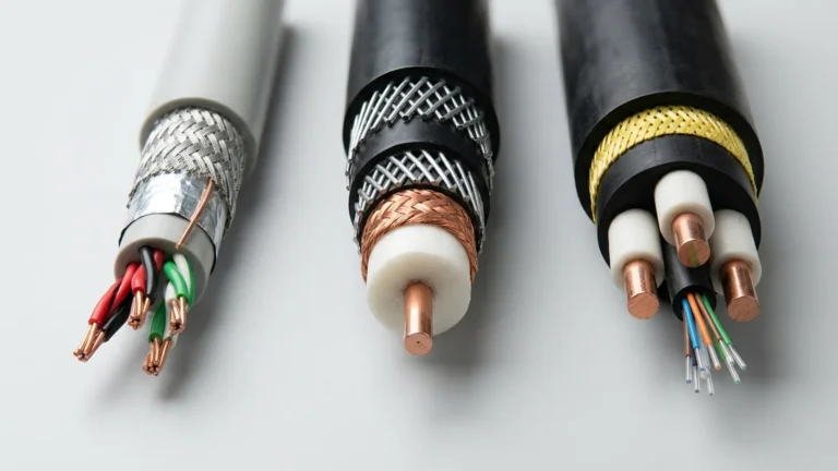
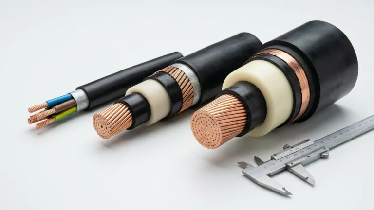
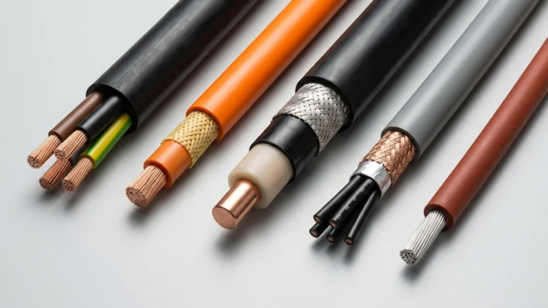
Engineering summary: Once a North American conductor exceeds 4/0 AWG (211.6 kcmil / 107.2 mm²), wire gauge numbering stops and cross-sectional area is specified in kcmil (formerly MCM), where 1 kcmil equals 1,000 circular mils or 0.5067 mm². Converting kcmil feeders to metric IEC 60228 sizes requires checking both copper cross-section and fine-stranded outer diameter so compression lugs and cable glands fit without derating.
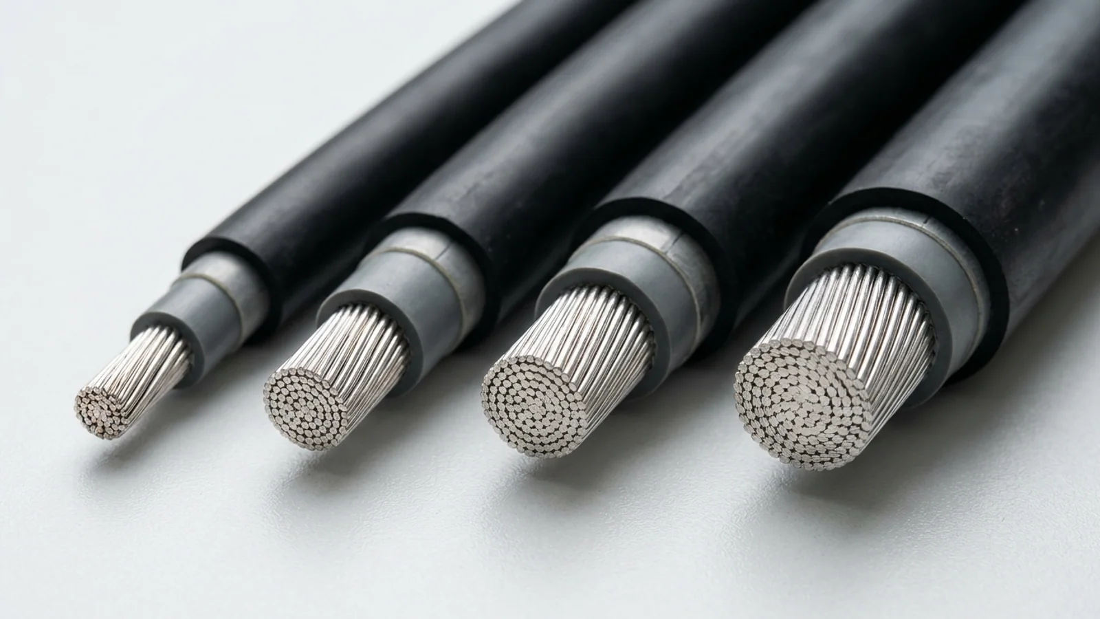
International mining, power generation, oilfield drilling, and switchgear projects routinely mix North American equipment schedules (written in NEC/UL kcmil or MCM) with European or IEC feeder specifications (written in metric mm²). Picking the closest-looking metric number without calculating exact area delta and conductor stranding diameter causes two expensive field failures: undersized phases that exceed thermal limits, or flexible rope-lay conductors that refuse to enter standard Class B compression lugs.
What Do kcmil and MCM Mean, and Why Does AWG Stop at 4/0?
One kcmil (identical to one legacy MCM) equals 1,000 circular mils—the area of a circle with a diameter of 0.001 inches (1 mil)—which converts to exactly 0.5067075 mm². American Wire Gauge (AWG) stops at 4/0 AWG (0000 AWG = 211.6 kcmil = 107.2 mm²), after which all larger North American power conductors are designated directly by their circular-mil area.
Because the Roman numeral M stood for one thousand, older North American drawings wrote 250 MCM or 500 MCM to mean 250,000 or 500,000 circular mils. To eliminate confusion with metric SI prefixes where M denotes mega (million), the National Electrical Code (NEC), UL, and IEEE standardized on kcmil (kilo-circular mils). Mechanically and electrically, 500 kcmil and 500 MCM are 100% identical.
- Exact kcmil to mm² formula:
Area (mm²) = kcmil × 0.5067075 - Exact mm² to kcmil formula:
Area (kcmil) = mm² × 1.973525 - Smaller gauge reference (4/0 AWG and below): For control, branch, and smaller portable cords between 30 AWG and 4/0 AWG, use our AWG to mm² conversion and current rating chart or our 4/0 DLO ampacity and weight guide.
Standard kcmil (MCM) to mm² Conversion Chart (250 kcmil to 2000 kcmil)
Standard NEC and ASTM B8 concentric power conductors step in fixed increments from 250 kcmil (126.7 mm²) to 2000 kcmil (1013.4 mm²). Because IEC 60228 metric sizes follow a different geometric series (120, 150, 185, 240, 300, 400, 500, 630, 800, and 1000 mm²), substituting a metric cable always requires selecting the next larger IEC cross-section whenever the nominal neighbor falls more than 1–2% below the kcmil copper area.
| kcmil / MCM Size | Exact Area (cmil) | Exact Metric Area (mm²) | Class B Strands & Bare OD | Nearest IEC 60228 Upsize (Area Delta) | NEC 310.16 Copper Ampacity (75 °C / 90 °C)* |
|---|---|---|---|---|---|
| 4/0 AWG (Ref.) | 211,600 | 107.22 mm² | 19 strands • 13.4 mm | 120 mm² (+11.9%) [95 mm² is −11.4%] | 230 A / 260 A |
| 250 kcmil | 250,000 | 126.68 mm² | 37 strands • 14.6 mm | 150 mm² (+18.4%) [120 mm² is −5.3%] | 255 A / 290 A |
| 300 kcmil | 300,000 | 152.01 mm² | 37 strands • 16.0 mm | 185 mm² (+21.7%) [150 mm² is −1.3%] | 285 A / 320 A |
| 350 kcmil | 350,000 | 177.35 mm² | 37 strands • 17.3 mm | 185 mm² (+4.3%) | 310 A / 350 A |
| 400 kcmil | 400,000 | 202.68 mm² | 37 strands • 18.5 mm | 240 mm² (+18.4%) [185 mm² is −8.7%] | 335 A / 380 A |
| 500 kcmil | 500,000 | 253.35 mm² | 37 strands • 20.7 mm | 300 mm² (+18.4%) [240 mm² is −5.3%] | 380 A / 430 A |
| 600 kcmil | 600,000 | 304.02 mm² | 61 strands • 22.7 mm | 400 mm² (+31.6%) [300 mm² is −1.3%] | 420 A / 475 A |
| 750 kcmil | 750,000 | 380.03 mm² | 61 strands • 25.4 mm | 400 mm² (+5.3%) | 475 A / 535 A |
| 1000 kcmil | 1,000,000 | 506.71 mm² | 61 strands • 29.3 mm | 630 mm² (+24.3%) [500 mm² is −1.3%] | 545 A / 615 A |
| 1250 kcmil | 1,250,000 | 633.38 mm² | 91 strands • 32.7 mm | 630 mm² (−0.5%, verify voltage drop) | 590 A / 665 A |
| 1500 kcmil | 1,500,000 | 760.06 mm² | 91 strands • 35.9 mm | 800 mm² (+5.3%) | 625 A / 705 A |
| 1750 kcmil | 1,750,000 | 886.74 mm² | 127 strands • 38.8 mm | 1000 mm² (+12.8%) | 650 A / 735 A |
| 2000 kcmil | 2,000,000 | 1013.42 mm² | 127 strands • 41.5 mm | 1000 mm² (−1.3%, verify fault I²t) | 665 A / 750 A |
Critical substitution trap (250 kcmil ≠ 120 mm² and 500 kcmil ≠ 240 mm²): The two most common field mistakes on international EPC projects are replacing 250 kcmil (126.7 mm²) with 120 mm² and replacing 500 kcmil (253.4 mm²) with 240 mm². Both metric substitutes remove 5.3% of copper cross-section, increasing DC resistance and risking thermal trip or inspection rejection on NEC/UL breaker terminals rated strictly at 75 °C.
Why Do Flexible Power & DLO Cables Use 262.6, 313.1, 373.7, 444.4, 535.3 & 777.7 kcmil?
Extra-flexible industrial power cables—most notably 2 kV Diesel Locomotive Cable (DLO), Type W, Type G-GC, and SHD-GC mining feeders—are stranded from multiples of 24 AWG (0.0201 in / 0.511 mm) tinned copper wires, where each wire equals 404 circular mils, producing non-round totals such as 262.6, 313.1, 373.7, 444.4, 535.3, and 777.7 kcmil.
Rigid Class B feeders use only 37 or 61 thick copper rods that cannot bend into compact switchgear compartments, generator tap boxes, or drag-line festoons. Building a rope-lay flexible conductor requires symmetric sub-bundles (such as 19 × 25, 37 × 25, or 37 × 35 strands of 24 AWG wire). Multiplying total strand count N by 404 cmil per 24 AWG wire yields the exact industry-standard DLO kcmil series found on 2 kV DLO flexible power cables, 2 kV Type G-GC mining cables, and 2–25 kV Type SHD-GC trailing cables.
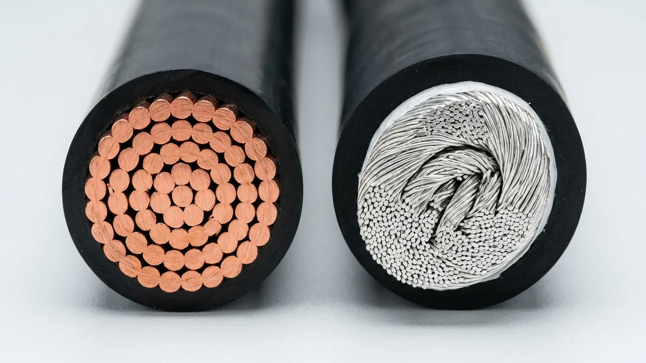
Stranding Geometry: Class B (37-Wire) vs. Flexible DLO (1,325-Wire)
- Class B Concentric 500 kcmil (Left): Packs 37 thick bare copper wires into ~20.7 mm conductor diameter inside rigid XLPE insulation; high spring-back torque in tight enclosures.
- Flexible Class I / K 535.3 kcmil DLO (Right): Bundles 1,325 tinned 24 AWG strands in rope-lay groups (~22.4 mm bare OD) beneath separator tape and EPR/CPE rubber—bending cleanly at 4×D to 6×D.
Rope-lay interstices expand bare conductor diameter by 8–14% over Class B conductors of similar kcmil rating.
| Flexible DLO Designation | 24 AWG Strand Construction | Exact Metric Area (mm²) | Nominal Bare Conductor OD | Typical 2 kV DLO Overall OD | Free-Air 90 °C / Conduit 75 °C Rating** |
|---|---|---|---|---|---|
| 262.6 kcmil (262 MCM) | 650 / 24 AWG (26×25) | 133.06 mm² | 15.5 mm (0.61 in) | 23.9 mm (0.94 in) | 445 A / 265 A |
| 313.1 kcmil (313 MCM) | 775 / 24 AWG (31×25) | 158.65 mm² | 17.0 mm (0.67 in) | 25.7 mm (1.01 in) | 513 A / 295 A |
| 373.7 kcmil (373 MCM) | 925 / 24 AWG (37×25) | 189.36 mm² | 18.5 mm (0.73 in) | 27.4 mm (1.08 in) | 579 A / 330 A |
| 444.4 kcmil (444 MCM) | 1100 / 24 AWG (44×25) | 225.18 mm² | 20.3 mm (0.80 in) | 29.5 mm (1.16 in) | 652 A / 365 A |
| 535.3 kcmil (535 MCM) | 1325 / 24 AWG (53×25) | 271.24 mm² | 22.4 mm (0.88 in) | 32.0 mm (1.26 in) | 728 A / 405 A |
| 646.4 kcmil (646 MCM) | 1600 / 24 AWG (64×25) | 327.54 mm² | 24.6 mm (0.97 in) | 34.8 mm (1.37 in) | 815 A / 445 A |
| 777.7 kcmil (777 MCM) | 1925 / 24 AWG (77×25) | 394.07 mm² | 26.9 mm (1.06 in) | 37.6 mm (1.48 in) | 904 A / 495 A |
| 929.3 kcmil (929 MCM) | 2300 / 24 AWG | 470.88 mm² | 29.5 mm (1.16 in) | 40.9 mm (1.61 in) | 1005 A / 540 A |
| 1111.1 kcmil (1111 MCM) | 2750 / 24 AWG | 562.95 mm² | 32.3 mm (1.27 in) | 44.5 mm (1.75 in) | 1115 A / 590 A |
*NEC Table 310.16 values assume not more than three current-carrying copper conductors in raceway/cable at 30 °C ambient. **Free-air 90 °C values reflect single-conductor ICEA S-95-658 / NEC Table 310.17 ratings; equipment terminals rated 75 °C per UL 489 limit usable current to the 75 °C column unless 90 °C switchgear bus transitions are certified.
How Do Compression Lugs, Skin Effect, and Parallel Runs Change Above 500 kcmil?
Above 500 kcmil (253 mm²), alternating-current skin and proximity effects disproportionately raise AC resistance while large conductor stiffness multiplies installation labor—making parallel runs of two or three 350–535.3 kcmil flexible cables with UL-listed flared-barrel compression lugs more efficient than pulling a single 1000–2000 kcmil feeder.
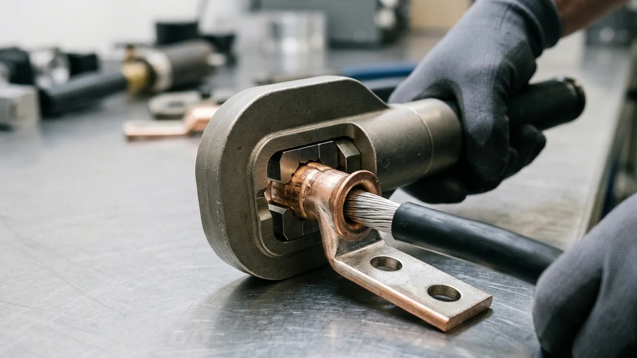
- Flared-barrel flex lugs are mandatory: Never force a 535.3 kcmil DLO or IEC Class 5/6 conductor into a standard straight-entry Class B lug, and never shave outer copper strands to make it fit. Specify flex-listed flared-entry (bell-mouth) two-hole NEMA compression lugs matched to the exact DLO/flex kcmil code.
- AC skin & proximity effect penalty: Doubling copper area from 500 kcmil to 1000 kcmil (+100% copper weight) increases NEC 75 °C conduit ampacity from 380 A to only 545 A (+43.4%) because 50/60 Hz current crowds toward the outer conductor skin. Running two parallel 250 kcmil or 262.6 kcmil DLO leads per phase delivers 510–530 A using virtually half the total copper mass per ampere.
- Equal-length parallel phase groups: Under NEC 310.10(H) and IEC 60364-5-52, parallel single-core feeders (
1/0 AWG/50 mm²and larger) must share identical conductor length, cross-section, insulation type (EPR/CPEor 5–15 kV flexible Type MV-105), and symmetrical trefoil cleat arrangement. Review our electrical switchgear and substation cable selection guide and LV, MV & HV cable voltage ratings guide for non-magnetic gland plate rules.
Frequently Asked Questions
Is MCM the exact same unit as kcmil?
Yes. Both 1 MCM and 1 kcmil equal exactly 1,000 circular mils (0.5067075 mm²). MCM is the older Roman-numeral abbreviation for thousand circular mils, while kcmil is the modern NEC, UL, and IEEE designation adopted to avoid confusion with metric mega-prefixes.
What is the metric mm² equivalent of 500 kcmil (500 MCM) cable?
A 500 kcmil conductor has an exact metallic cross-section of 253.35 mm² (or 271.24 mm² for flexible 535.3 kcmil DLO). When substituting an IEC 60228 metric cable, 300 mm² is the compliant upsize because 240 mm² is 5.3% smaller in copper area.
Why do DLO cables list 535.3 kcmil and 777.7 kcmil instead of 500 and 750 kcmil?
Flexible DLO conductors are assembled from rope-lay bundles of 24 AWG tinned copper strands (404 circular mils per strand). Symmetric bundle counts of 1,325 strands (535,300 cmil = 535.3 kcmil) and 1,925 strands (777,700 cmil = 777.7 kcmil) create round, torque-balanced conductors that exceed the copper area of standard 500 and 750 kcmil cables.
Can TEBAOFLEX manufacture dual-marked or custom metric/kcmil heavy rubber power cables?
Yes. TEBAOFLEX manufactures both North American kcmil constructions (2 kV DLO, Type W, Type G-GC, SHD-GC, and Type MV-105 up to 1111.1 kcmil) and IEC/VDE metric flexible rubber cables (H07RN-F, NSSHÖU, and (N)TSCGEWÖU up to 500–630 mm²), supplying exact bare conductor diameters so your compression lugs and glands match before shipment.
Request Large-Cross-Section kcmil or Metric Cable Engineering Support
Specifying high-current generator leads, switchgear bus jumpers, or open-pit mining feeders requires matching conductor stranding, insulation temperature rating, and lug barrel dimensions. TEBAOFLEX produces fine-stranded tinned and bare copper rubber cables from 4/0 AWG through 1111.1 kcmil and 630 mm².
- Submit your North American kcmil / MCM schedule or IEC mm² feeder list for exact cross-reference verification.
- Confirm bare conductor diameter, insulation wall thickness, overall cable OD, and minimum bending radius prior to ordering lugs and glands.
- Request cut-to-length drum schedules and export packaging for mining, marine, power generation, or OEM switchgear projects.
Standards & technical references: ASTM B8, B33 & B172 (Concentric and rope-lay stranded copper conductors); IEC 60228 (Conductors of insulated cables); NFPA 70 / NEC Article 310 & UL 44 (RHH/RHW-2 ampacity and insulation); ICEA S-95-658 / NEMA WC 70 & ICEA S-75-381 (2 kV power and portable mining cables); UL 486A-486B (Wire connectors for fine-stranded conductors).