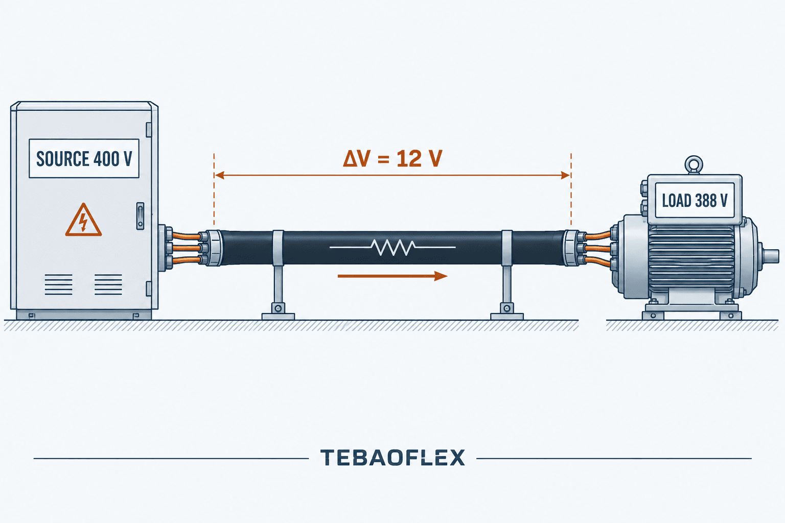
Voltage drop is the difference between the voltage available at the power source and the voltage that reaches the load. In a short, lightly loaded circuit it may be small. In a long feeder, a low-voltage DC system, a motor circuit or a continuously moving cable, it can become a practical design limit.
This guide explains cable voltage drop calculation for DC, single-phase AC and balanced three-phase AC circuits. It also shows how cable length, conductor size, temperature, material, power factor and reactance affect the result. The worked examples are intended to help engineers and technical buyers compare options; final cable selection must still be checked against the applicable installation code, equipment limits, short-circuit duty and the cable manufacturer’s verified data.
What Is Voltage Drop in a Cable?
Every conductor has electrical resistance, and an AC circuit also has reactance. When current flows through that impedance, part of the source voltage is lost along the cable. The load therefore receives less voltage than the source terminals provide. In simple terms:
Load voltage = source voltage − cable voltage drop
Excessive voltage drop can cause weak motor starting torque, contactor dropout, dim lighting, nuisance control faults, longer heating times and inefficient operation. Low-voltage systems are especially sensitive because the same loss in volts represents a larger percentage of the supply. A 2 V loss is only 0.5% of 400 V, but it is 4.17% of 48 V.
The Main Factors That Determine Voltage Drop
Current
Voltage drop increases in direct proportion to current when the cable impedance is unchanged. Use the design current that represents the real operating condition, and separately check starting, inrush or transient current where the connected equipment requires it. A cable that performs well at a motor’s running current may still allow an unacceptable voltage dip during starting.
Circuit length
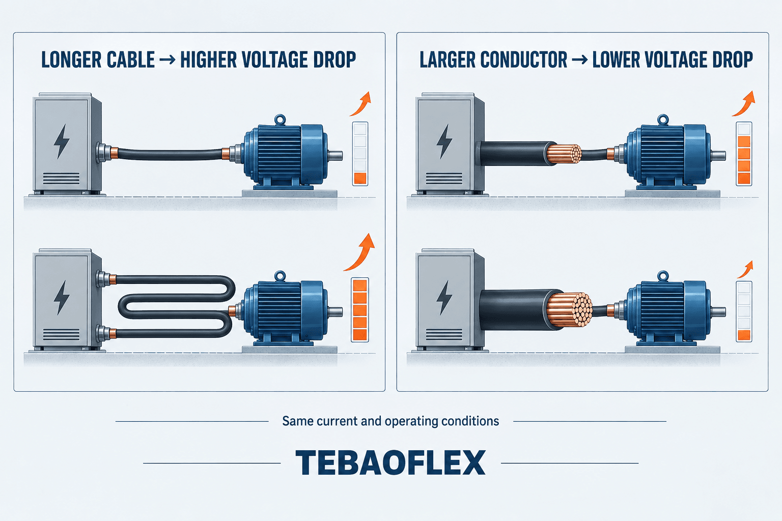
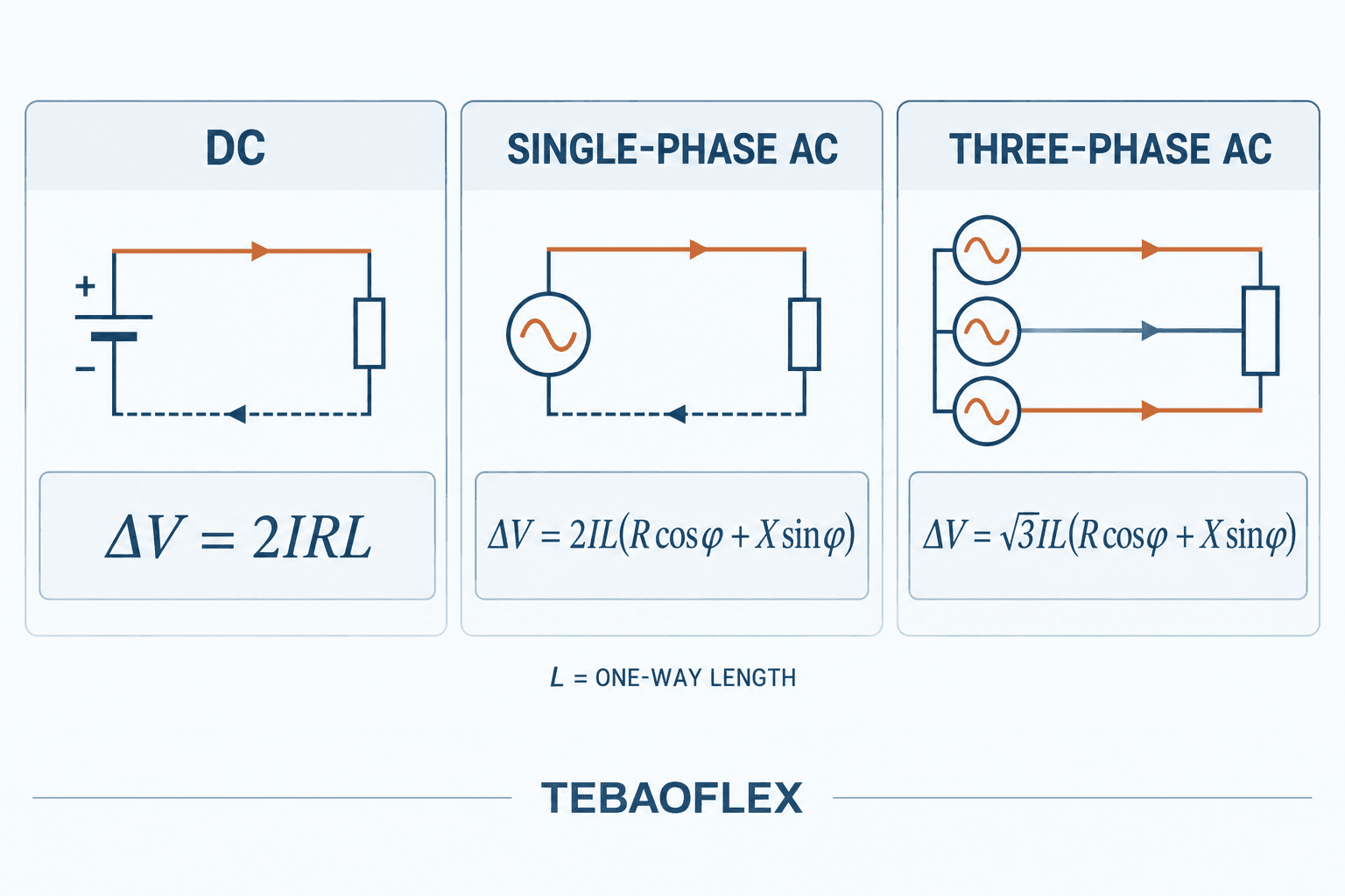
A longer route creates more conductor resistance and reactance. In this article, L means one-way route length. The DC and single-phase formulas include a factor of 2 for the outgoing and return paths. Do not double the length again if the data or calculator already uses loop length.
Conductor cross-sectional area
For the same material and length, a larger conductor has lower resistance and therefore lower voltage drop. Increasing cross-section is a common solution, but it changes cable diameter, weight, bending force, termination size, drum capacity and cost. These mechanical effects are particularly important for festoon, reeling and other moving-cable systems.
Conductor material and temperature
Copper and aluminum do not have the same resistivity, so equal cross-sections do not produce equal voltage drop. Resistance also rises as conductor temperature increases. The Copper Development Association notes that temperature is a major factor in conductor resistance and voltage drop. For project calculations, use resistance values at the expected operating temperature or apply the appropriate temperature correction—not only a room-temperature value. See our detailed comparison of copper and aluminum conductors.
Power factor and reactance
For AC systems, voltage drop depends on resistance R, reactance X and load power factor. Ignoring reactance may be acceptable for an early estimate in some short, low-voltage circuits, but it is not a universal shortcut. Long feeders, larger conductors, grouped single-core cables and loads with lower power factor require the complete AC expression and verified cable data.
Cable Voltage Drop Formulas
Two calculation approaches are useful. A resistivity-based formula is convenient for a preliminary DC or resistive estimate. A design calculation should normally use the cable manufacturer’s resistance and reactance values, corrected for operating temperature and installation conditions.
| System | Formula | When to use it |
|---|---|---|
| DC, two-wire | ΔV = 2 × I × R × L | When R is conductor resistance per unit length and L is one-way length |
| DC, resistivity method | ΔV = 2 × I × ρ × L / A | Preliminary estimate using material resistivity and conductor area |
| Single-phase AC | ΔV = 2 × I × L × (R cosφ + X sinφ) | Single-phase circuit using resistance, reactance and power factor |
| Balanced three-phase AC | ΔV = √3 × I × L × (R cosφ + X sinφ) | Balanced three-phase circuit |
| Voltage drop percentage | ΔV% = (ΔV / system voltage) × 100 | Comparison with the project or equipment limit |
The symbols are:
- ΔV: voltage drop in volts
- I: load current in amperes
- L: one-way cable length in the same length unit used for R and X
- R: conductor AC resistance per unit length at the relevant operating temperature
- X: conductor reactance per unit length
- ρ: conductor resistivity
- A: conductor cross-sectional area
- cosφ: load power factor; sinφ = √(1 − cos²φ)
Keep units consistent. If R and X are stated in Ω/km, enter L in kilometres. If the manufacturer’s table gives values in Ω/1000 ft, use thousands of feet. For parallel conductors, do not simply insert the resistance of one conductor; use the effective circuit arrangement and confirm current sharing.
Worked Example 1: 48 V DC Circuit
Consider a 48 V DC load drawing 20 A. The total loop resistance of the positive and negative conductors at the expected operating temperature is 0.08 Ω.
- Voltage drop: ΔV = I × Rloop = 20 × 0.08 = 1.6 V.
- Voltage drop percentage: 1.6 / 48 × 100 = 3.33%.
- Voltage at the load: 48 − 1.6 = 46.4 V.
Whether 46.4 V is acceptable depends on the load’s permitted input range, the source tolerance, the applicable rules and the operating state. A battery system, for example, must be checked at its lowest expected source voltage rather than only at nominal voltage.
Worked Example 2: Single-Phase AC Feeder
Assume a 230 V single-phase load draws 32 A through a 40 m one-way cable route. At the design temperature, the selected cable data gives R = 1.15 Ω/km and X = 0.08 Ω/km. The load power factor is 0.90, so sinφ is approximately 0.436.
ΔV = 2 × 32 × 0.04 × (1.15 × 0.90 + 0.08 × 0.436) = 2.74 V
ΔV% = 2.74 / 230 × 100 = 1.19%
This is an illustrative calculation, not a cable recommendation. The final result must use resistance and reactance for the actual cable construction, conductor temperature, frequency and installation arrangement.
Worked Example 3: Balanced Three-Phase Motor Feeder
Consider a 400 V balanced three-phase load drawing 100 A over a 50 m one-way route. For illustration, R = 0.60 Ω/km, X = 0.08 Ω/km and power factor cosφ = 0.80, giving sinφ = 0.60.
ΔV = √3 × 100 × 0.05 × (0.60 × 0.80 + 0.08 × 0.60) = 4.57 V
ΔV% = 4.57 / 400 × 100 = 1.14%
The running result may look acceptable, but a motor also needs a starting-voltage check. Starting current, starting method, source impedance and allowable acceleration time can make the transient condition more demanding than normal operation.
What Is an Acceptable Voltage Drop?
There is no single percentage that is correct for every country, installation and load. Values such as 3% are frequently used as design targets, but they must not be treated as universal rules. Requirements can differ between lighting and other loads, public and private supplies, branch circuits and feeders, continuous operation and starting conditions.
The correct limit should be established from the applicable national code, project specification, supply arrangement and equipment manufacturer’s allowable terminal voltage. The Electrical Installation Guide’s voltage-drop guidance illustrates how typical limits can vary by installation type and load. IEC 60364-5-52 is also a relevant reference for the selection and erection of low-voltage wiring systems; consult the edition adopted in the project jurisdiction.
Voltage Drop Is Not the Same as Ampacity
Ampacity asks whether a cable can carry current without exceeding its permitted conductor temperature under defined installation conditions. Voltage drop asks whether adequate voltage reaches the load. A cable can pass one check and fail the other.
| Check | Primary question | Typical inputs |
|---|---|---|
| Ampacity | Will the conductor remain within its temperature limit? | Current, ambient temperature, grouping, installation method, insulation rating |
| Voltage drop | Will sufficient voltage reach the load? | Current, length, R, X, power factor, source voltage |
| Short-circuit withstand | Can the conductor survive the fault energy until protection clears? | Prospective fault current, clearing time, conductor and insulation data |
| Mechanical suitability | Will the cable withstand its real movement and environment? | Bending radius, torsion, tensile load, speed, oil, abrasion, temperature |
Start with the cable ampacity calculation guide, then verify voltage drop, fault protection and the installation-specific mechanical requirements. Our cable cross-section selection guide brings these checks together.
Cable Resistance, AWG and mm²
Voltage drop is an application result; cable resistance is one of its inputs. Resistance depends on conductor material, cross-section, length, construction and temperature. For the underlying relationship and correction approach, read our cable resistance formula guide.
AWG and metric cross-sections are different sizing systems. A nominal AWG size should not be replaced with a visually similar mm² value without comparing actual conductor area, resistance and terminal compatibility. The AWG current rating guide explains why current capacity also varies with insulation and installation conditions.
Voltage Drop in Motors and Industrial Equipment
Industrial feeders often supply motors, cranes, conveyors, pumps, winches and mobile machinery. These loads combine long routes with starting current, motion and demanding environments. The cable calculation must therefore be integrated with equipment behaviour rather than completed as an isolated spreadsheet exercise.
- Motor starting: check the lowest terminal voltage during starting and confirm that torque remains adequate.
- Contactors and brakes: verify pickup and holding voltage, particularly on long control circuits.
- Variable-frequency drives: follow the drive and motor manufacturers’ cable-length, EMC, shielding and output-filter requirements. A steady-state 50/60 Hz voltage-drop result does not cover reflected-wave effects or high-frequency common-mode current.
- 400 Hz systems: obtain impedance data appropriate to the operating frequency; do not assume 50/60 Hz reactance values apply unchanged.
- Medium-voltage circuits: use a full system study and project-specific cable parameters rather than only the simplified equations in this guide.
Flexible and Moving Cables Need More Than a Larger Conductor
Upsizing reduces resistance, but it also increases cable mass and often the minimum bending radius. On a festoon trolley, reeling drum or robotic system, that can increase mechanical load and reduce the available installation space. The correct decision balances electrical performance with conductor flexibility, stranding, reinforcement, sheath material, bending radius, travel speed and duty cycle.
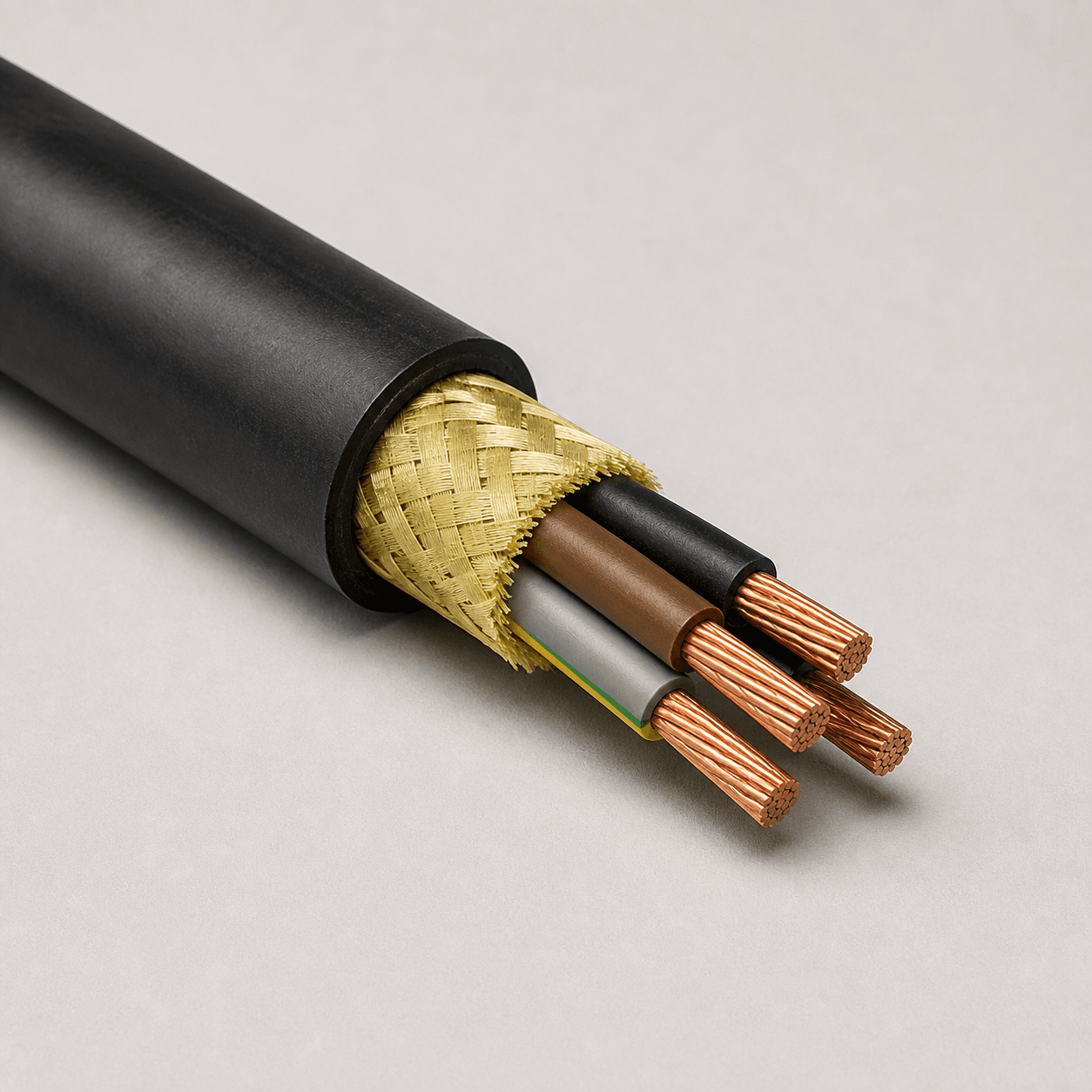
For mobile mining and industrial machinery, BUFLEX-M PUR cable is another application-specific option to review. The cable construction and project conditions must be confirmed before its electrical parameters are used in a calculation.
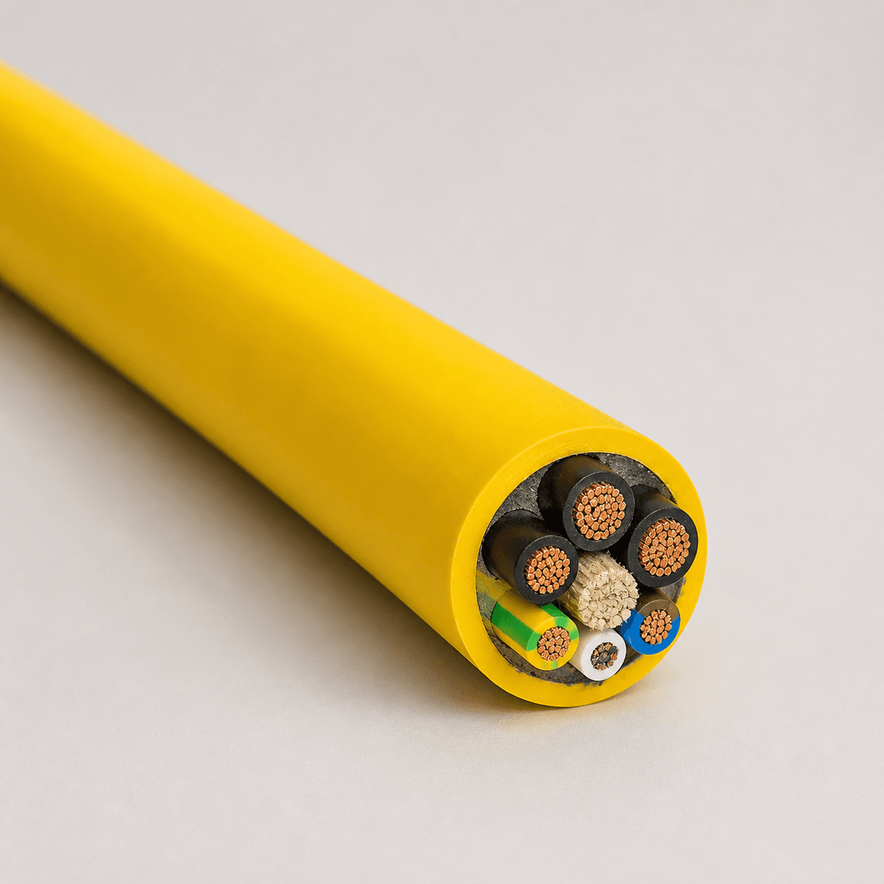
Where fire performance or marine/offshore construction is part of the specification, review the verified requirements of the BFOU 0.6/1 kV fire-resistant power cable. For aircraft ground power, the operating frequency changes the calculation context; see the 400 Hz airport ground power cable. These links identify product families for further technical review, not automatic selections for the examples above.
A Practical Cable Size Selection Process
- Define the system. Record DC, single-phase or three-phase voltage, frequency, source tolerance and earthing arrangement.
- Define the load. Confirm running current, power factor, efficiency, starting method, duty cycle and allowable terminal-voltage range.
- Measure the route. Use the real one-way cable length, including vertical travel, loops, drum allowance and termination routing.
- Choose a candidate cable. Select a construction suitable for voltage rating, environment and mechanical duty.
- Obtain verified electrical data. Use conductor resistance at the expected temperature and reactance for the actual cable arrangement and frequency.
- Calculate voltage drop. Apply the correct system formula and keep all units consistent.
- Check every relevant condition. Compare normal operation, starting or inrush, lowest source voltage and any emergency operating mode with the project limit.
- Complete the other sizing checks. Confirm ampacity, short-circuit withstand, protective-device operation, installation method, bending radius and termination capacity.
- Document assumptions. Record the data source, temperature, length definition, formula and acceptance criterion so the result can be reviewed.
Common Voltage Drop Calculation Mistakes
| Mistake | Why it matters | Better practice |
|---|---|---|
| Using one-way length in a two-wire DC formula without the factor of 2 | Understates the circuit resistance | Confirm whether the formula and data use one-way or loop length |
| Using room-temperature resistance | Understates drop when the conductor operates hotter | Use corrected operating-temperature resistance |
| Ignoring power factor and reactance | Can distort AC feeder results | Use manufacturer R and X data with the complete AC expression |
| Checking running current only | Misses motor starting or equipment inrush | Calculate normal and transient conditions separately |
| Selecting by ampacity alone | A thermally adequate cable may deliver insufficient voltage | Complete voltage-drop, fault and mechanical checks |
| Assuming 3% is always mandatory | Applies a rule without confirming jurisdiction or equipment | Use the applicable code, project specification and load limits |
| Rounding to the nearest cable size too early | Can conceal a marginal result | Keep precision through the calculation, then select an available size |
Frequently Asked Questions
1. How do I calculate voltage drop in a DC cable?
For a two-wire DC circuit, use ΔV = 2IRL when R is the resistance of one conductor per unit length and L is one-way length. Alternatively, use ΔV = 2IρL/A for a preliminary resistivity-based estimate. Use resistance at the expected conductor temperature.
2. Why is √3 used for three-phase voltage drop?
In a balanced three-phase system, line-to-line voltages are separated by 120 electrical degrees. The phasor relationship produces the √3 factor in the line-to-line voltage-drop expression.
3. Should cable length be one way or round trip?
In the formulas shown here, L is one-way length. DC and single-phase formulas already include 2 for the outgoing and return conductors. Some tables and calculators use loop length, so always check the stated convention.
4. Does increasing cable size reduce voltage drop?
Yes. For the same material and conditions, a larger cross-sectional area lowers resistance. However, the larger cable’s diameter, weight, bending radius, termination size and moving-system loads must also be acceptable.
5. Is 3% the maximum permitted voltage drop?
Not universally. It is a common design value in some contexts, but the applicable limit depends on local rules, project requirements, circuit type and equipment tolerance.
6. Do flexible conductors have the same resistance as solid conductors?
Do not assume so from nominal area alone. Conductor class, strand construction, material and manufacturing tolerances affect the published resistance. Use the verified maximum resistance or actual cable data for the specified product.
7. Can I use the same formula for VFD motor cables?
The fundamental circuit calculation is useful for steady-state voltage drop, but it does not cover every VFD output-cable effect. Follow the drive and motor manufacturers’ limits for cable length, shielding, EMC, reflected waves and output filters.
8. What information should I provide for a cable voltage-drop review?
Provide system voltage and frequency, phase arrangement, load current and power factor, starting current or inrush, one-way route length, installation method, ambient temperature, cable movement, environmental exposure and the required voltage-drop limit.
Conclusion: Calculate the Circuit, Then Select the Cable
A reliable cable voltage drop calculation begins with the correct circuit model and verified cable data. Current and length increase the drop; larger conductor area reduces it; temperature, material, power factor and reactance can materially change the answer. The result must then be evaluated together with ampacity, fault duty, protective-device performance and the mechanical demands of the application.
If you are selecting a cable for a crane, reeling system, mobile machine, marine installation, airport ground power system or another demanding application, TEBAOFLEX can review the operating data and cable-construction requirements. Send your voltage, current, one-way length, installation conditions and movement requirements to request a cable recommendation and quotation.
Technical references: Calculation of voltage drop in steady load conditions; Copper wire installation recommendations. Always apply the standards and regulations adopted for the project location.