Cable power loss occurs because every practical conductor has electrical resistance. When current flows through that resistance, part of the electrical power is converted into heat. The basic conductor-loss relationship is Ploss = I²R, so resistive loss rises with the square of current—not in direct proportion to current.
That square-law effect matters in high-current DC systems, long cable runs, motors, mining equipment, cranes, battery circuits and other heavy-duty power connections. A cable may carry the required current and still create avoidable energy loss, voltage drop and heat. However, an I²R calculation does not replace ampacity, voltage-drop, short-circuit, protection or thermal-design checks.
| Change | Resistance | I²R power loss |
|---|---|---|
| Current doubles | Same | 4× |
| Current triples | Same | 9× |
| Cable length doubles | Approximately 2× | Approximately 2× |
| Conductor area doubles | Approximately ½ | Approximately ½ |
| Conductor temperature rises | Increases for copper and aluminum | Increases at the same current |
These simplified relationships assume the other relevant electrical and operating conditions remain unchanged.
What Is Cable Power Loss?
A power source supplies energy to a load through a cable. Most useful power reaches the load, but some real power is dissipated in the current-carrying conductors. That conductor loss appears mainly as heat. For low-voltage conductor-sizing work, I²R loss is normally the first loss to calculate.
It is not the only possible cable loss. Depending on voltage, cable construction, bonding arrangement, conductor size and frequency, a complete study can also include AC resistance effects, metallic sheath or armour losses and dielectric losses. IEC 60287-1-1 provides current-rating and loss calculations for steady-state cable operation, while related parts address specific sheath-loss cases. For an initial low-voltage comparison, however, conductor I²R loss gives a clear and useful starting point.
Cable Power Loss Formula
The fundamental conductor-loss formula is:
Ploss = I² × R
| Symbol | Meaning | Unit |
|---|---|---|
| Ploss | Real electrical power converted to conductor heat | W or kW |
| I | RMS current through the conductor or phase | A |
| R | Resistance of the conductor path represented in the calculation | Ω |
The U.S. Department of Energy’s Advanced Conductor Scan Report uses this same relationship and explains that doubling current increases line loss fourfold when conductor resistance is unchanged.
Why is current squared?
Ohm’s law gives the conductor voltage drop as V = IR. Power is P = VI. Substituting IR for V gives P = I × IR = I²R. The first current term represents charge flow; the second appears because voltage drop itself rises with current through a fixed resistance.
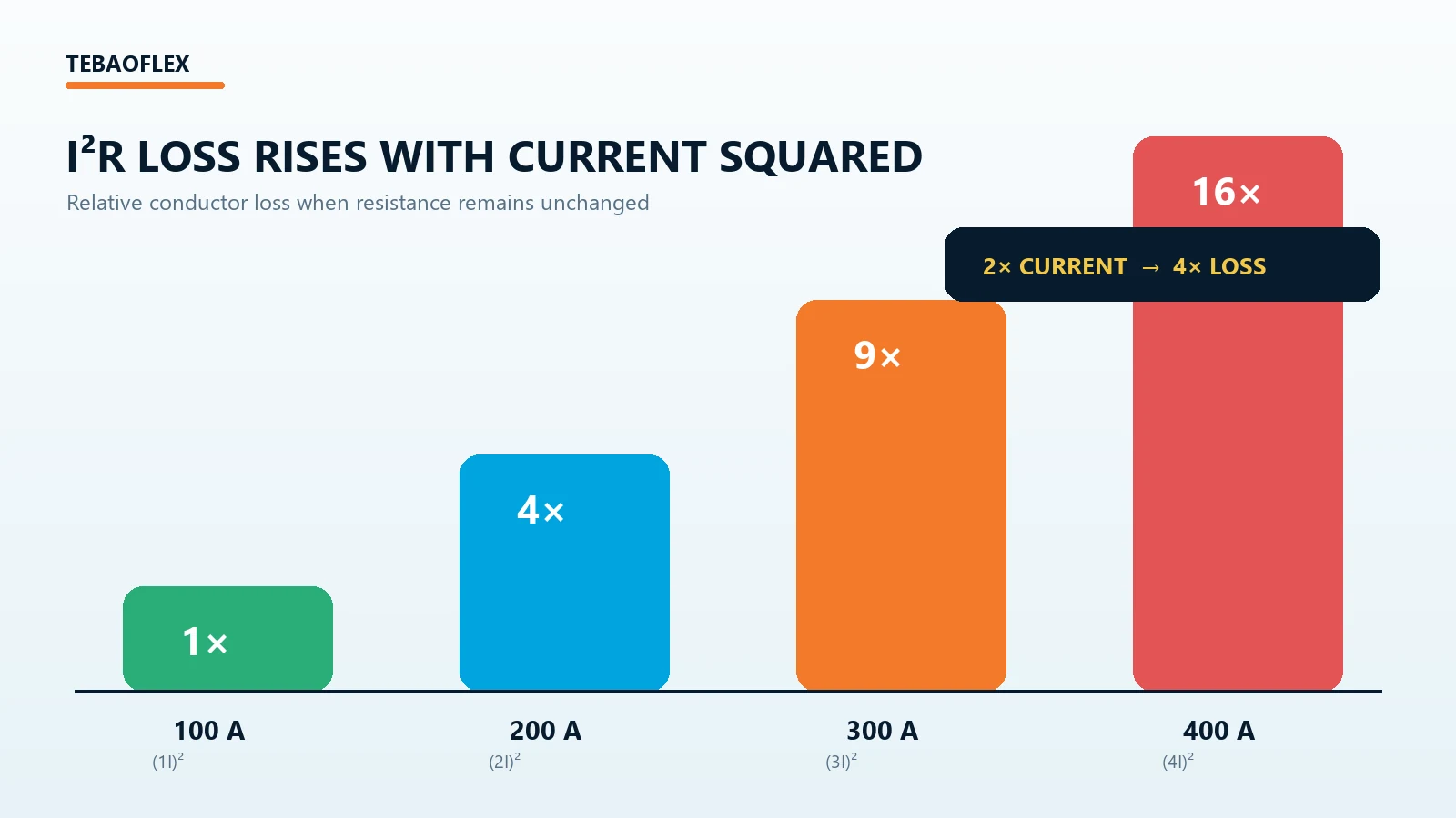
| Current | Relative I²R loss when R is unchanged |
|---|---|
| I | 1× |
| 2I | 4× |
| 3I | 9× |
| 4I | 16× |
Doubling current does not double cable loss; it increases resistive loss by approximately four times when resistance remains unchanged.
Where Does Cable Resistance Come From?
For a uniform conductor, the simplified DC relationship is R = ρL/A. Resistivity ρ depends on the conductor material, L is conductor length and A is conductor cross-sectional area. Temperature also changes resistance. The detailed cable resistance formula guide explains these inputs and the distinction between nominal DC resistance and the value needed for an operating cable.
A loss calculation must use the resistance of the actual current path. Do not insert an Ω/km value directly as though it were total ohms. Multiply resistance per unit length by the relevant conductor length, account for outgoing and return paths where required, and use data appropriate to the operating temperature and AC conditions.
How Cable Length Affects Power Loss
With material, cross-section and temperature unchanged, resistance increases approximately in proportion to conductor length. At a fixed current, I²R loss therefore also increases approximately in proportion to length. A 100 m route does not automatically mean 100 m of resistance: a two-wire DC circuit normally has an outgoing and a return conductor, so the represented path can be about 200 m before connections are considered.
Route length, current path and units must be stated explicitly. The guide to how cable length affects resistance and voltage drop covers this geometry in more detail.
How Conductor Size Affects Cable Power Loss
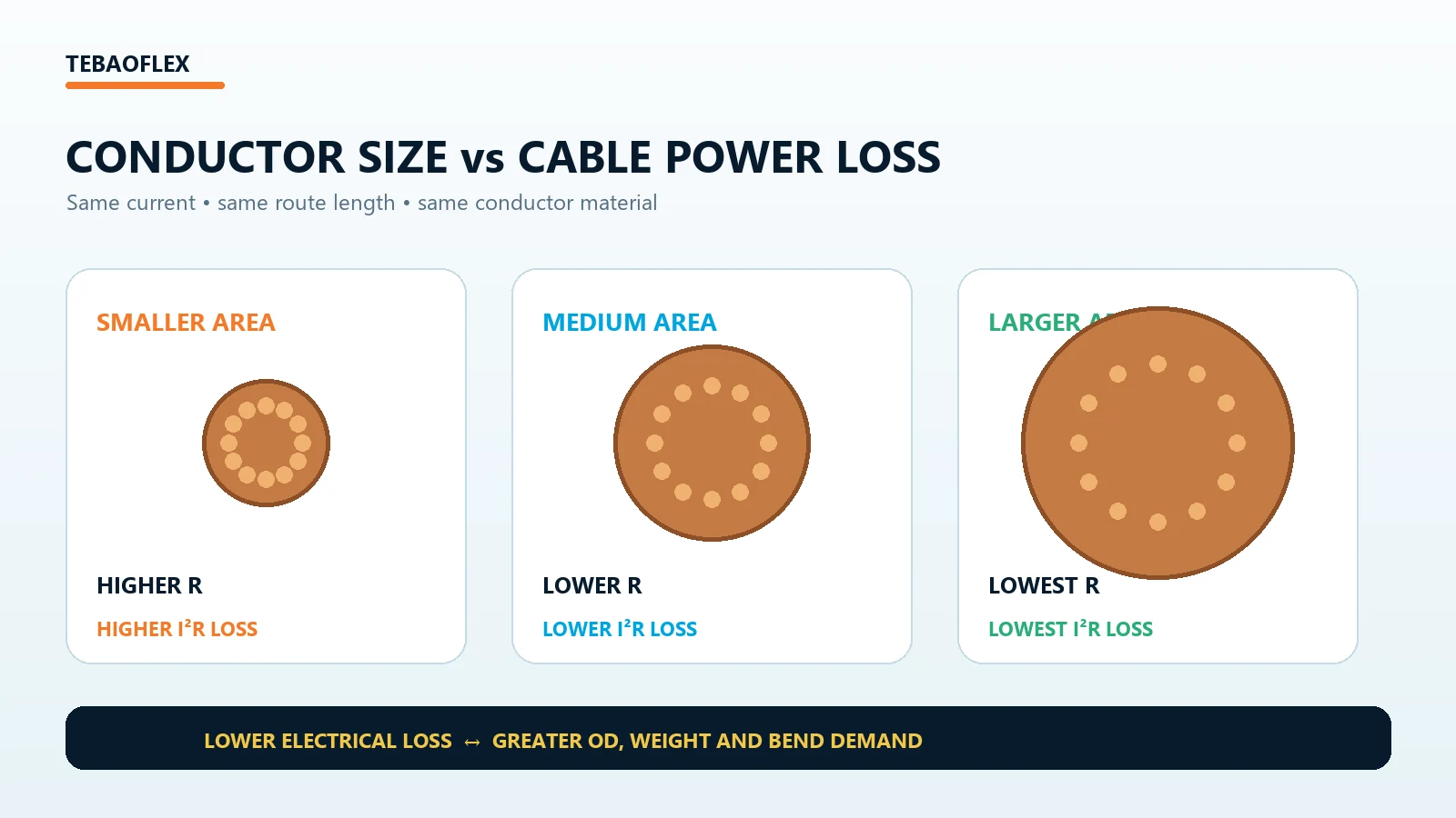
For the same material, length and temperature, increasing conductor cross-section lowers resistance. At the same current, lower resistance means lower I²R loss. This is why voltage-drop or energy-efficiency requirements can push a design to a larger conductor than the minimum size identified by an initial ampacity check.
| Conductor choice | Resistance tendency | I²R loss at the same current | Mechanical consequence |
|---|---|---|---|
| Smaller cross-section | Higher | Higher | Usually lower mass and smaller diameter |
| Medium cross-section | Lower | Lower | Intermediate installation demand |
| Larger cross-section | Lowest of the three | Lowest of the three | Usually greater mass, OD and bend requirement |
A larger cable is not automatically the best cable. Cost, outside diameter, termination size, bending radius, reel capacity, festoon load and moving mass can all increase. Use the amps-to-cable-size workflow to establish a defensible candidate, then compare its electrical and mechanical performance.
Worked Example: Power Loss in a High-Current DC Cable
Assume a 200 A DC circuit has a measured or calculated total loop resistance of 0.020 Ω, including the represented outgoing and return conductors.
Ploss = 200² × 0.020 = 800 W
The conductor system therefore dissipates approximately 0.8 kW at that operating point. Its resistive voltage drop is:
ΔV = I × R = 200 × 0.020 = 4 V
For this simple DC resistive path, the same result can be checked as Ploss = I × ΔV = 200 × 4 = 800 W. This is an illustrative calculation, not a cable-size recommendation.
Voltage Drop vs Power Loss: Related, Not the Same
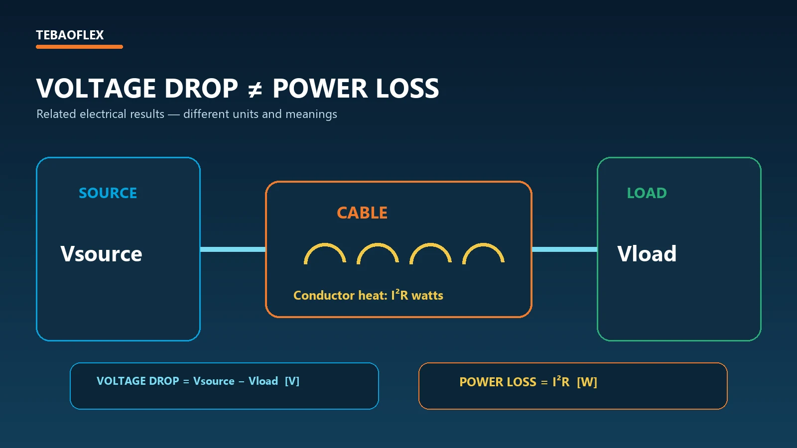
Voltage drop is measured in volts or percent and describes the reduction between source and load. Power loss is measured in watts or kilowatts and describes real electrical power converted mainly to conductor heat. In a simple DC resistive circuit, Ploss = I × ΔV connects the two quantities.
In AC circuits, voltage drop can include resistance R and reactance X. The reactive component affects voltage regulation but is not equivalent to real conductor heating. Real conductor loss remains principally I²R, using the appropriate AC resistance. Therefore, “1% voltage drop” should not be treated automatically as “1% cable power loss.” See the full cable voltage drop calculation method for the R, X and power-factor relationship.
DC, Single-Phase and Three-Phase Cable Loss Formulas
Two-wire DC cable power loss
If r is one-conductor resistance per unit length and L is one-way length, a simple two-wire circuit with equal outgoing and return conductors gives:
Ploss = 2 × I² × r × L
The factor of two represents both conductors. A chassis return, parallel conductors, unequal conductors or additional connectors requires the actual current path instead. The DC cable voltage drop and sizing guide explains loop resistance and why joints matter in low-voltage, high-current assemblies.
Single-phase cable power loss
For a two-conductor single-phase circuit with equal current-carrying conductors:
Ploss ≈ 2 × I² × Rconductor
Here Rconductor is the effective resistance of one full-length conductor, not resistance per kilometre. For AC work, use an applicable AC resistance at the relevant operating temperature.
Balanced three-phase cable power loss
For a balanced three-phase system with negligible neutral current and equal phase conductors:
Ploss = 3 × I² × Rphase
If r is phase-conductor resistance per unit length, then Ploss = 3I²rL. Use operating-temperature AC resistance rather than blindly applying a theoretical 20°C DC value. For motor feeders, current must first come from verified motor data or a properly defined power calculation; see three-phase motor cable sizing.
Worked three-phase example
Assume a balanced 100 A circuit, a 50 m one-way route and conductor AC resistance of 0.60 Ω/km at the stated operating condition. Each phase conductor has R = 0.60 × 0.05 = 0.03 Ω. Total conductor loss is:
Ploss = 3 × 100² × 0.03 = 900 W
That is 0.9 kW across the three phase conductors. It is an illustrative conductor-loss calculation, not a cable recommendation.
How Temperature Increases Cable Loss
The resistance of copper and aluminum conductors increases as conductor temperature rises. At unchanged current, higher R produces higher I²R loss. NIST’s Copper Wire Tables gives a 20°C temperature coefficient of 0.00393 per °C for 100% conductivity copper and shows how resistance ratios can be calculated between temperatures.
Heating and resistance therefore interact: current produces I²R heat, warmer metal has greater resistance, and greater resistance raises loss at the same current. This does not imply unlimited thermal runaway. The stable temperature depends on the balance between heat generation and heat dissipation through insulation, sheath, surrounding air, ground, tray or other installation environment.
Cable Heating vs Ampacity
I²R explains heat generation. Ampacity asks whether the complete cable installation can carry current continuously without exceeding applicable temperature limits. The same conductor can have different allowable current in free air, a grouped tray, conduit, thermal insulation or hot ambient conditions because heat dissipation changes.
That distinction is why loss alone cannot approve a cable. Complete the cable ampacity calculation, including the applicable installation and derating method. IEC’s IEC 60287-1-1 overview likewise frames current rating as a steady-state thermal calculation involving cable construction and ambient conditions.
Why High-Current, Low-Voltage Systems Need Special Attention
For a given power requirement, a lower system voltage generally requires higher current. Because loss depends on I², low-voltage high-power systems can become highly sensitive to conductor, lug and connector resistance. At unchanged resistance, moving from 100 A to 200 A creates four times the conductor loss; moving to 400 A creates sixteen times the loss.
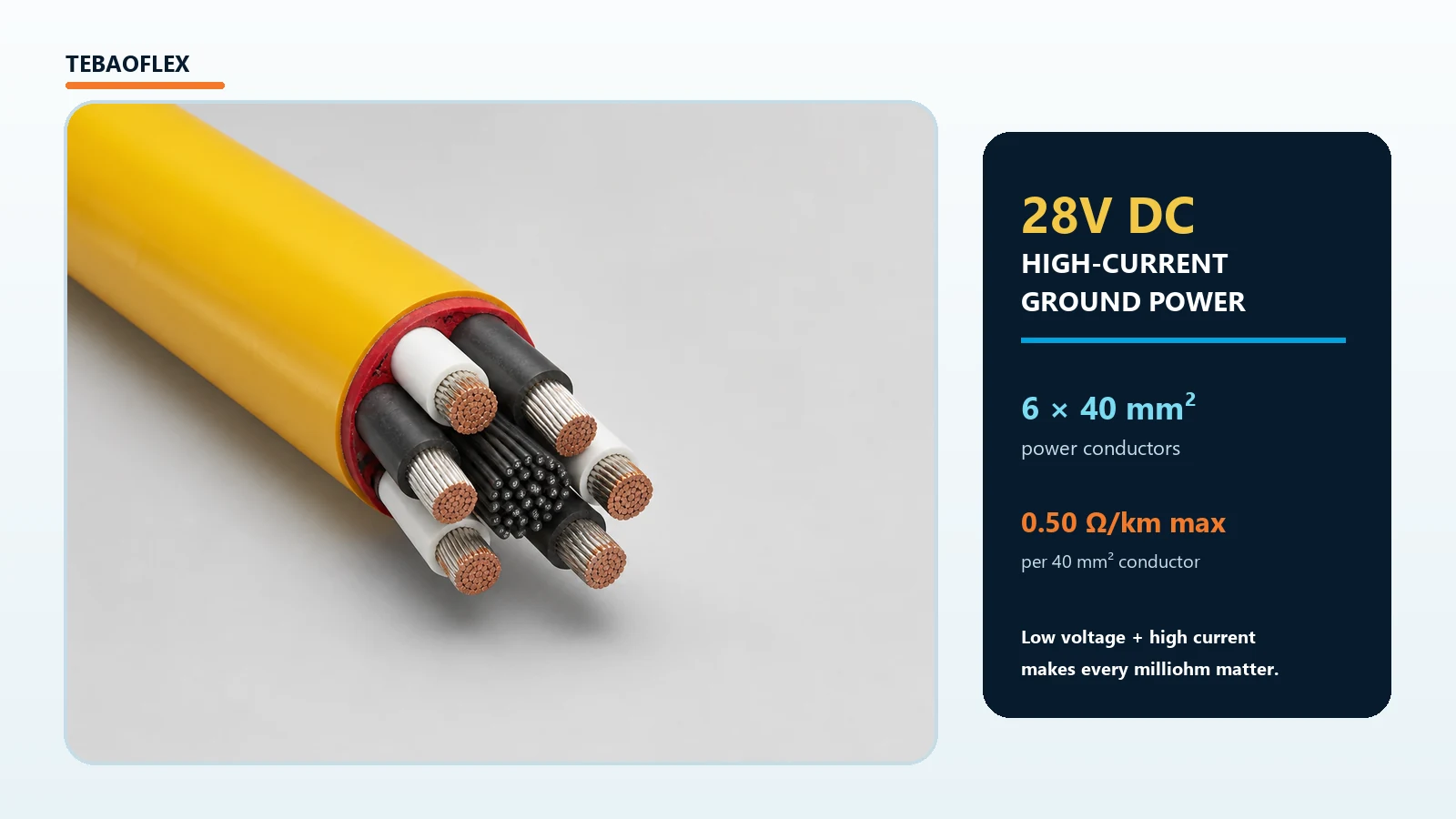
A practical example is a 28V DC aircraft ground power cable. The published product data lists a 6 × 40 mm² power-conductor configuration and maximum resistance of 0.50 Ω/km for each 40 mm² conductor. Manufacturer data is more useful than a generic theoretical value because the actual cable construction is already defined; engineers must still map that value to the real parallel current paths, route, connectors and operating temperature.
Can higher system voltage reduce I²R loss?
For the same real power transfer and comparable assumptions, raising voltage reduces the required current and can sharply reduce I²R loss. The preceding DOE report highlights this relationship. However, voltage must never be increased solely as a cable-loss shortcut unless the equipment, insulation, protection, connectors, clearances and complete system architecture are designed for it. Use the watts-to-amps relationships only as an input to full system engineering.
Power Loss, Cable Size and Energy Efficiency
A larger conductor normally has lower resistance and operating loss, but it also costs and weighs more, occupies more space, needs larger terminations and can require a larger bending radius. The optimum is not “the largest possible cable”; it is the cable that satisfies electrical, thermal, mechanical, installation and economic requirements with an appropriate design margin.
The BUFLEX-M flexible industrial power cable shows this real trade-off. Across its listed constructions, phase-conductor sizes rise from 25 to 240 mm² while cable outside diameter, mass and dynamic bending radius also increase. That matters on moving machinery, reels and festoons: electrical loss can fall while mechanical load rises.
For flexible high-current links in locomotives, switchgear, mining machinery, motors, generators and battery systems, the DLO flexible high-current power cable provides single-conductor sizes from 14 AWG to 1111.1 kcmil. Final selection must still confirm ampacity, voltage, installation, terminations, route and flexibility—not loss alone.
Cable Power Loss and Annual Energy Consumption
Power loss becomes an energy quantity when operating time is included:
Eloss = Ploss × t
If a cable dissipates 0.8 kW for 4,000 operating hours per year, annual conductor energy loss is 3,200 kWh/year. Annual energy cost can then be estimated as energy loss multiplied by the applicable electricity tariff. Duty cycle, load profile and operating hours must be realistic; a continuously loaded conveyor is different from an intermittent crane or ground-power cable.
Cable loss percentage
With the source-power basis defined, cable loss percentage can be expressed as:
Cable loss % = Ploss / Psource × 100
State whether the denominator is source input, load input or another system boundary. Do not substitute voltage-drop percentage for power-loss percentage, especially in an AC circuit where reactance affects voltage drop.
When I²R Alone Is Not Enough
Simple I²R is an excellent model for conductor resistive loss, but a complete study may need AC resistance, skin effect, proximity effect, metallic sheath and armour losses, dielectric loss, harmonic current and frequency-dependent behavior. This is particularly relevant to large conductors, medium-voltage cables and non-sinusoidal systems.
VFD output is not a simple utility-frequency sine wave. RMS current, switching-frequency components, screen and grounding design, drive manufacturer limits and cable construction all require review. Do not size a VFD or medium-voltage cable from nominal 20°C DC resistance and I²R alone.
How to Reduce Cable Power Loss
Reduce total circuit resistance
Use verified conductor data, the real current path and suitable materials. Include parallel paths, joints and terminations rather than modelling only the cable core.
Increase conductor cross-section where engineering supports it
Compare candidate sizes using operating-temperature resistance and the actual duty cycle, then verify termination capacity, cable mass, outside diameter and bend limits.
Reduce unnecessary route length
A shorter practical route lowers resistance, voltage drop and I²R loss. Do not compromise segregation, protection, service access or minimum bending radius merely to save length.
Reduce current through appropriate system design
Higher voltage or distributed conversion can reduce current in some systems, but this is a whole-system engineering decision—not a field modification to an existing cable circuit.
Maintain low-resistance connections
Correct lug selection, crimping, contact preparation, torque, strain relief and inspection are critical. A small contact resistance at a high-current joint can create concentrated heating that a cable-only calculation misses.
Cable Power Loss vs Resistance, Voltage Drop and Ampacity
| Parameter | Main question | Unit |
|---|---|---|
| Resistance | How strongly does the conductor path oppose current? | Ω |
| Voltage drop | How much voltage is lost before the load? | V or % |
| Power loss | How much real electrical power becomes heat? | W or kW |
| Ampacity | How much current can the cable carry under stated conditions? | A |
Cable Power Loss Calculation Workflow
- Determine operating current from verified load data.
- Obtain conductor resistance from applicable manufacturer or standard data.
- Correct resistance for relevant temperature and AC conditions.
- Map the actual outgoing, return, phase, neutral and parallel current paths.
- Calculate conductor loss with I²R for each loaded path.
- Calculate voltage drop separately using the applicable DC or AC method.
- Check ampacity, installation derating and steady or cyclic thermal conditions.
- Compare candidate conductor sizes on both loss and mechanical consequences.
- Verify protection, fault withstand, terminations, routing and movement before final selection.
Frequently Asked Questions
What is I²R loss in a cable?
It is real electrical power converted to heat when current flows through conductor resistance. The basic relationship is Ploss = I²R.
How do you calculate cable power loss?
Determine the current and resistance of every relevant current-carrying path, then sum I²R loss across those paths. Use operating-temperature AC resistance for AC systems where applicable.
Does doubling current double cable power loss?
No. When resistance is unchanged, doubling current increases I²R loss by four times.
Does a larger cable reduce power loss?
Usually, because a larger conductor cross-section normally has lower resistance. Final size must also satisfy ampacity, voltage drop, fault, termination, installation and mechanical requirements.
Does cable length increase power loss?
Yes. With other conditions unchanged, a longer conductor has higher resistance, so its I²R loss increases approximately in proportion to length.
Is cable power loss the same as voltage drop?
No. Voltage drop is measured in volts; power loss is measured in watts. They are related, but AC voltage drop can include reactance that is not real conductor heat.
Does cable resistance increase when it gets hot?
Yes for common copper and aluminum conductors across normal cable operating ranges. Engineering calculations should use resistance appropriate to the expected conductor temperature.
Is I²R loss the same as ampacity?
No. I²R describes heat generation. Ampacity is the allowable continuous current under specified cable, ambient and installation conditions.
Is three-phase cable power loss calculated differently?
Yes. For a balanced three-phase circuit with equal phase conductors and negligible neutral current, total phase-conductor loss is commonly calculated as 3I²Rphase.
Need Help Reducing Cable Loss in a High-Current Application?
Send TEBAOFLEX your system voltage, operating current, cable length, conductor size, duty cycle, installation method, ambient temperature and movement requirements. Our team can review conductor resistance, voltage drop, ampacity and the mechanical implications of alternative cable sizes for your application.