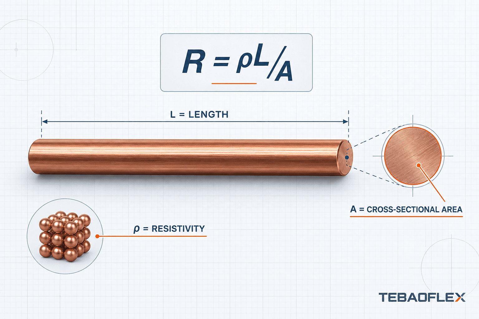
The cable resistance formula explains how conductor material, conductor length, cross-sectional area and temperature affect electrical resistance. For a uniform conductor, the theoretical value can be estimated with R = ρL/A, where ρ is resistivity, L is conductor length and A is conductor cross-sectional area.
That calculation is a useful engineering estimate, but a real industrial cable is not an ideal solid conductor. Stranding, conductor class, manufacturing tolerances, temperature and the applicable cable standard also matter. For specification and compliance work, the calculated result should therefore be checked against the conductor resistance stated in the relevant standard or manufacturer’s technical data.
What Is Cable Resistance?
Cable resistance is the opposition that a conductor presents to the flow of electric current. It is measured in ohms (Ω), or often expressed as resistance per unit length, such as Ω/m or Ω/km. No practical copper or aluminum conductor has zero resistance.
When current passes through a cable, conductor resistance contributes to:
- voltage drop between the source and the load;
- I²R power loss in the conductor;
- conductor heating;
- the required conductor size for a given route;
- system efficiency over long cable runs.
The relationship between voltage, current and resistance is explained in our guide to Ohm’s Law for electrical cables. This article focuses on the next question: what determines the resistance value of the cable itself?
Cable Resistance Formula
For a uniform conductor at a stated temperature, resistance can be estimated using:
R = ρ × L ÷ A
| Symbol | Meaning | Typical unit in metric cable calculations |
|---|---|---|
| R | Conductor resistance | Ω |
| ρ | Electrical resistivity of the conductor material | Ω·mm²/m |
| L | Conductor length | m |
| A | Conductor cross-sectional area | mm² |
Unit consistency is essential. If resistivity is expressed in Ω·mm²/m, length can be entered in metres and cross-sectional area in mm². If resistivity is expressed in Ω·m, the area must be converted to square metres. Mixing the two unit systems can produce an error of one million times.
What is resistivity (ρ)?
Resistivity is a material property. Conductors made from different metals have different resistance even when their length and cross-sectional area are identical. Copper has lower resistivity than aluminum at the same reference temperature, while aluminum offers different weight and cost characteristics.
The material decision should not be reduced to resistance alone. Connections, conductor size, mass, installation method, corrosion considerations and the applicable standard all affect the final choice. See our detailed comparison of copper vs aluminum conductors for the broader engineering context.
How cable length affects resistance
Resistance is proportional to conductor length: R ∝ L. If material, area and temperature remain unchanged, a 100 m conductor has approximately ten times the resistance of a 10 m conductor.
| Conductor length | Relative resistance |
|---|---|
| 10 m | 1× |
| 20 m | 2× |
| 50 m | 5× |
| 100 m | 10× |
This relationship makes route length important for mobile equipment, battery systems, long crane feeds and remote industrial loads. It also makes the distinction between one-way length and complete circuit length essential.
How cross-sectional area affects resistance
Resistance is inversely proportional to conductor cross-sectional area: R ∝ 1/A. Under the same conditions, doubling the conductor area approximately halves its theoretical resistance. A larger area provides more conductive material for current flow.
Cross-sectional area is the metallic conductor area in mm²—not the cable’s outside diameter. A cable with a 25 mm outside diameter does not necessarily contain a 25 mm² conductor. Insulation, screens, fillers, reinforcement and the outer sheath all contribute to overall cable diameter.
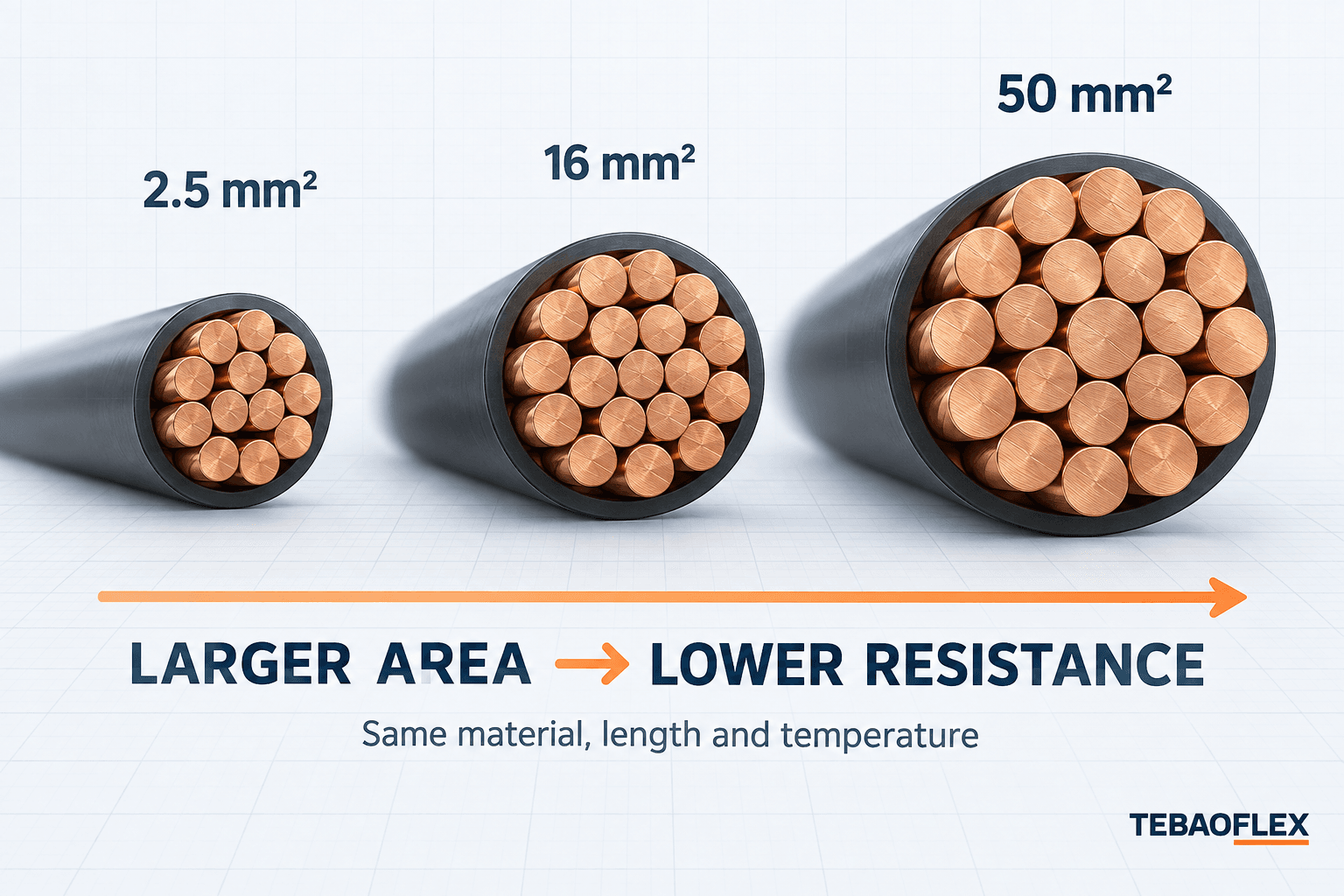
Resistance is only one input in conductor sizing. Our cable size and cross-section selection guide covers the additional checks needed for current, voltage drop, installation and mechanical duty.
How temperature affects cable resistance
The resistance of metallic conductors normally increases as temperature rises. A simplified correction can be written as:
RT = R20 × [1 + α(T − 20)]
Here, R20 is resistance at 20°C, T is the conductor temperature in °C and α is the material’s temperature coefficient for the method being used. A room-temperature calculation therefore does not automatically represent a conductor operating under load in a hot environment.
Use the correction method required by the applicable standard or project specification. Do not combine a generic temperature coefficient with a standard limit unless the calculation basis is confirmed.
How to Calculate Cable Resistance Step by Step
Step 1 — Identify the conductor material
Confirm whether the conductor is copper, tinned copper, aluminum or another specified material. Use resistivity data appropriate to that material and the stated reference temperature. Do not assume that every “copper cable” uses the same conductor construction or calculation basis.
Step 2 — Determine conductor length
Decide whether the calculation concerns one conductor or the complete circuit path. If the source-to-load route is 50 m, the resistance of one conductor uses L = 50 m. A simple two-wire DC circuit may have 50 m outgoing plus 50 m return, giving a total conductor path of 100 m.
One-way length and loop length are not interchangeable. Always state which one is used. For multi-core, grounded, parallel or three-phase systems, follow the calculation method appropriate to the circuit rather than automatically doubling every route length.
Step 3 — Find conductor cross-section
Use the conductor’s nominal mm² size or the relevant AWG/kcmil designation. If the project is specified in American Wire Gauge, consult the AWG to mm² conductor size guide. AWG and metric sizes are different designation systems, so their values should not be treated as exact replacements without checking the product and standard.
Step 4 — Apply the formula with consistent units
Insert resistivity, conductor length and cross-sectional area into R = ρL/A. Record the assumed material, temperature, one-way or circuit length, and whether the result represents one conductor or a loop. Those notes are necessary if the result will be reviewed later.
Cable Resistance Calculation Example
Consider a simplified 50 m copper power conductor with a nominal cross-sectional area of 25 mm². For this educational example, use approximate copper resistivity at 20°C:
ρ ≈ 0.0172 Ω·mm²/m
The resistance of one 50 m conductor is:
R = 0.0172 × 50 ÷ 25 = 0.0344 Ω
If the same 50 m route forms a simple two-wire DC circuit, the outgoing and return conductors give a 100 m path:
Rloop = 0.0172 × 100 ÷ 25 = 0.0688 Ω
These are simplified theoretical values. They do not include connector resistance, temperature rise, material tolerance or other installation effects. For product verification, use the specified maximum conductor resistance and the relevant test basis.
Key relationship: doubling conductor length approximately doubles resistance, while doubling conductor cross-sectional area approximately halves resistance, assuming the same material and temperature.
Cable Resistance vs Cable Length: Practical Comparison
The following values use the same theoretical assumptions as the example: copper, 25 mm² and approximately 0.0172 Ω·mm²/m at 20°C.
| Single-conductor length | Approximate theoretical resistance |
|---|---|
| 10 m | 0.0069 Ω |
| 25 m | 0.0172 Ω |
| 50 m | 0.0344 Ω |
| 100 m | 0.0688 Ω |
| 200 m | 0.1376 Ω |
Values are rounded, simplified theoretical calculations using nominal resistivity. They should not replace a cable datasheet, measured resistance or an applicable conductor standard.
How Cable Size Changes Resistance
For a fixed material and length, increasing cross-sectional area lowers resistance. This qualitative comparison uses a 100 m copper conductor at the same reference temperature:
| Nominal cross-section | Relative resistance |
|---|---|
| 2.5 mm² | Highest in this comparison |
| 6 mm² | Lower |
| 16 mm² | Lower again |
| 35 mm² | Low |
| 70 mm² | Lowest in this comparison |
This does not mean that a conductor should be selected from resistance alone. Larger conductors affect cable weight, outside diameter, termination size, bend radius and cost. The complete cable construction must suit the electrical and mechanical application.
Calculated Resistance vs IEC 60228 Conductor Resistance
R = ρL/A describes an idealized relationship based on nominal material resistivity, conductor length, nominal area and temperature. A manufactured cable conductor may be solid or stranded and may use different conductor classes, strand diameters and lay arrangements. Material condition and production tolerances also influence the finished conductor.
IEC 60228:2023, Conductors of insulated cables, specifies nominal metric cross-sectional areas and includes requirements for conductor construction and resistance values. Its scope includes copper, aluminum and aluminum-alloy conductors for fixed installations, as well as flexible copper conductors. The standard also provides informative temperature-correction factors for resistance measurement.
For cable specification and compliance, use the applicable standard or manufacturer’s specified conductor resistance rather than relying only on a theoretical R = ρL/A result. The formula is valuable for understanding trends, early design estimates and checking the reasonableness of data; it is not a substitute for compliance documentation.
Class 2 vs Class 5 and Class 6 conductors
Conductor classes describe construction and flexibility requirements. Class 2 generally covers stranded conductors for fixed installations, while Class 5 and Class 6 cover flexible conductor constructions. More and finer strands can improve flexibility, but the conductor must still meet the resistance requirements applicable to its nominal size and class.
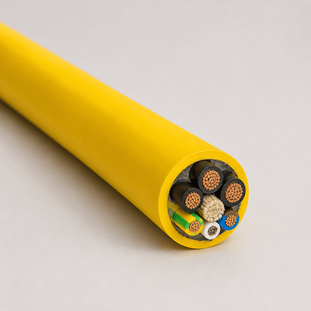
For flexible power and control duties, the BUFLEX-M flexible PUR power cable is one example of a product whose conductor size must be assessed together with the complete cable construction and movement requirements. Confirm current product data before specifying a configuration.
Cable Resistance vs Voltage Drop
When current flows through conductor resistance, it creates voltage drop:
Vdrop = I × R
Higher resistance or higher current therefore increases voltage drop in the same simple DC model. Cable resistance is one of the key inputs, but a full voltage-drop calculation must use the correct circuit length and method. AC systems may also require reactance, impedance and power factor.
This article intentionally stops at the resistance input. A separate guide will cover DC, single-phase and three-phase cable voltage-drop calculations without duplicating the conductor-resistance topic.
Cable Resistance Is Not the Same as Ampacity
Resistance describes a conductor’s opposition to current. Ampacity describes how much current a cable can carry continuously under stated thermal and installation conditions. They are related, but they are not interchangeable.
R = ρL/A cannot by itself prove that a cable can safely carry a specified current. Ampacity can depend on conductor size, insulation temperature, ambient conditions, installation method, grouping and heat dissipation. See the cable ampacity calculation guide for these additional factors.
DC Resistance vs AC Resistance
The basic formula R = ρL/A is principally a model for conductor DC resistance at a stated temperature. In AC systems, the effective conductor resistance can differ from the DC value. The significance depends on conductor size, construction, frequency and arrangement.
For larger conductors, higher frequencies, long circuits and VFD applications, the system assessment may need to consider:
- AC resistance;
- skin effect and proximity effect;
- inductive and capacitive reactance;
- overall cable impedance;
- shielding, grounding and EMC behavior;
- frequency-dependent losses and converter switching effects.
For industrial AC, motor and VFD systems, conductor DC resistance alone is not sufficient for a complete cable-system calculation. The cable manufacturer, equipment supplier and responsible engineer should confirm the method and input data appropriate to the system.
Common Cable Resistance Calculation Mistakes
Using cable outside diameter instead of conductor area
Cable outside diameter includes insulation, sheath, screens and other components. The A term in R = ρL/A is the metallic conductor cross-sectional area.
Ignoring the return conductor
A 50 m two-wire DC route can contain 100 m of current path. State whether the result is for one conductor or the complete loop.
Using the wrong resistivity units
Ω·m and Ω·mm²/m require different area units. Write down the units before substituting values into the formula.
Ignoring conductor temperature
A resistance value at 20°C is not automatically the operating resistance of a warm conductor. Apply the correction method required by the project or standard.
Treating AWG and mm² as exact equivalents
AWG and metric cross-sections belong to different sizing systems. Conversion charts are useful references, but final selection should use the actual product designation, conductor data and required standard.
Using theoretical resistance as a compliance value
Theoretical calculations support engineering estimates. Compliance should be verified against the applicable maximum conductor-resistance requirement, test report or manufacturer’s declared value.
How Cable Resistance Affects Industrial Cable Selection
A practical selection sequence moves from material, length and area to resistance, voltage drop and conductor size. It then checks the complete cable construction against the application.
Final selection should also consider:
- system voltage and ampacity;
- fixed, flexible, reeling, festoon or drag-chain movement;
- minimum bend radius and tensile load;
- ambient and conductor temperature;
- oil, water, UV, abrasion and chemical exposure;
- screening, grounding and control cores;
- applicable standards, approvals and project documentation.
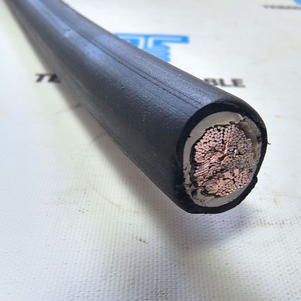
The DLO flexible single-conductor power cable provides a useful example of an AWG/kcmil product family. Its electrical data and flexible construction should be reviewed together rather than selecting from conductor size alone.
Frequently Asked Questions
What is the formula for cable resistance?
The basic cable resistance formula is R = ρL/A. R is resistance, ρ is material resistivity, L is conductor length and A is conductor cross-sectional area. Use a consistent unit system and state the conductor temperature and whether the length represents one conductor or the complete circuit path.
How do you calculate the resistance of a copper cable?
Select a copper resistivity value at the stated reference temperature, multiply it by conductor length and divide by conductor cross-sectional area. For a real product, compare the theoretical result with the manufacturer’s declared conductor resistance or the limit in the applicable standard.
Does a longer cable have more resistance?
Yes. If material, cross-section and temperature remain the same, conductor resistance increases approximately in proportion to length. Doubling conductor length approximately doubles theoretical resistance.
Does a larger cable have lower resistance?
A larger conductor cross-sectional area has lower resistance when material, length and temperature are unchanged. However, final cable size must also meet ampacity, voltage, mechanical, installation and termination requirements.
What is cable resistance measured in?
Resistance is measured in ohms (Ω). Cable data may state resistance as Ω/m or Ω/km at a reference temperature. Always confirm whether the value is nominal, typical or a specified maximum.
Does cable resistance increase with temperature?
For metallic conductors such as copper and aluminum, resistance normally increases with temperature. Use the applicable standard’s correction method or verified material data when converting between measurement and operating temperatures.
Is cable resistance the same as cable ampacity?
No. Resistance is an electrical property of the conductor, while ampacity is the permitted continuous current under defined installation and thermal conditions. A cable can have low resistance but still require ampacity, temperature and installation checks.
Need Help Calculating Cable Resistance or Selecting Conductor Size?
Send TEBAOFLEX the conductor material, cable length, required cross-section or load current, system voltage, installation method, movement requirements and working environment. Our team can help review the conductor size and identify a suitable flexible cable construction for your project.
Technical note: The calculations in this article are simplified educational examples. Final cable selection must use verified product data, applicable standards and project-specific engineering.