Voltage drop is especially important in DC power systems because a relatively small voltage loss can represent a significant percentage of the available supply. A 2 V drop has very different consequences in a 12 V or 24 V circuit than in a 270 V DC system.
DC cable sizing therefore requires more than checking ampacity. Engineers must consider load current, one-way cable length, conductor resistance, cross-sectional area, operating temperature, connection resistance and the minimum voltage required at the load. This guide explains DC cable voltage drop for 12 V, 24 V, 28 V, 48 V and 270 V industrial systems, with practical calculations and selection guidance. The actual allowable terminal voltage must always be checked against the connected equipment and the applicable project requirements.
Why Voltage Drop Matters More in Low-Voltage DC Systems
Voltage drop in volts is only part of the story. The percentage of the supply voltage determines how severely the load is affected. If every system below loses the same 2 V, the lower-voltage systems experience a much larger relative reduction.
| System voltage | 2 V drop as a percentage | Voltage reaching the load |
|---|---|---|
| 12 V DC | 16.7% | 10 V |
| 24 V DC | 8.3% | 22 V |
| 28 V DC | 7.1% | 26 V |
| 48 V DC | 4.2% | 46 V |
| 270 V DC | 0.74% | 268 V |
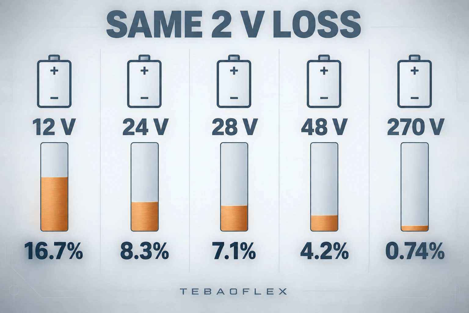
The lower the system voltage, the more significant a given number of lost volts becomes. This does not mean that 270 V systems can ignore voltage drop. High current, long cable assemblies, high conductor temperature or unsuitable connections can still create unacceptable loss and heating.
DC Cable Voltage Drop Formula
The most direct DC expression uses the total resistance of the current path:
ΔV = I × Rloop
For a simple two-wire circuit, when R is the resistance of one conductor per unit length and L is the one-way route length:
ΔV = 2 × I × R × L
For an early estimate based on conductor resistivity:
ΔV = 2 × I × ρ × L / A
| Symbol | Meaning | Required unit consistency |
|---|---|---|
| ΔV | Voltage drop | V |
| I | DC load current | A |
| Rloop | Total resistance of the complete current path | Ω |
| R | Resistance of one conductor per unit length | Ω/km or Ω/m |
| ρ | Conductor resistivity | Compatible with L and A |
| L | One-way cable route length | km or m to match R |
| A | Conductor cross-sectional area | Usually mm² |
Manufacturer or applicable conductor-specification resistance should normally be preferred to a purely theoretical ρL/A result. It reflects the defined conductor construction and maximum resistance value. IEC 60228:2023, for example, covers nominal cross-sectional areas and resistance requirements for several conductor types, including flexible copper conductors. For a fuller explanation of resistance and temperature correction, see our cable resistance formula.
Why Do We Multiply Cable Length by Two?
Current travels from the source to the load through the outgoing conductor and returns to the source through the return conductor. A 20 m one-way cable route therefore has approximately 40 m of conductor in a conventional two-wire loop.
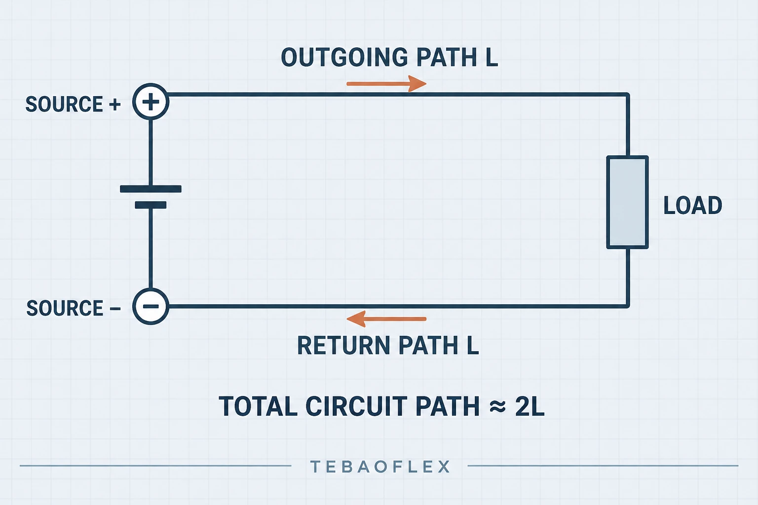
Do not apply ×2 blindly to every DC architecture. Parallel conductors, multi-core assemblies, chassis-return arrangements and project-specific power interfaces must be calculated from the actual current path and current distribution.
How to Calculate DC Cable Voltage Drop Step by Step
Step 1 — Determine the DC system voltage
Record the nominal voltage and its real operating range. A battery, generator, converter or ground-power unit may not hold exactly 12 V, 24 V, 28 V, 48 V or 270 V under every operating condition.
Step 2 — Determine continuous and peak current
Use the design current rather than only the equipment nameplate power. If power and voltage are known for a simple DC load, current can be estimated from I = P/V. Starting, inrush or peak current should be checked separately. The basic relationship is explained in Ohm’s Law for electrical cables.
Step 3 — Measure the actual one-way route
Measure the installed source-to-load path, not the straight-line distance. Include routing through cable trays, drag chains, reels, machine frames, ground equipment and service loops. Moving systems may need reserve length for travel.
Step 4 — Choose an initial conductor size
Select a starting cross-section from the design current, installation method, conductor material, ambient temperature and cable construction. Our cable size and cross-section selection guide explains the wider process.
Step 5 — Obtain conductor and connection resistance
Use verified resistance at the expected operating temperature. Include significant connector, lug, contact and joint resistance where appropriate, particularly in low-voltage high-current assemblies.
Step 6 — Calculate load voltage and percentage drop
Calculate ΔV = I × Rloop, then use:
Vload = Vsupply − ΔV
Voltage drop % = ΔV / Vsupply × 100
Compare the resulting terminal voltage with the equipment requirement, project specification and applicable rules. For single-phase and three-phase AC formulas, use the broader AC and DC cable voltage drop calculation guide.
12 V DC Cable Voltage Drop Example
A 12 V load draws 20 A. The verified total loop resistance of the installed cable and current path is 0.020 Ω.
- ΔV = 20 A × 0.020 Ω = 0.40 V.
- Voltage drop = 0.40 / 12 × 100 = 3.33%.
- Load voltage = 12 − 0.40 = 11.60 V.
The calculation does not by itself declare the design acceptable. Confirm that the connected equipment operates correctly at 11.60 V after also allowing for source-voltage variation.
24 V DC Cable Voltage Drop Example
Consider a 24 V industrial control circuit drawing 10 A over a 30 m one-way route. Assume the complete operating-temperature loop resistance, including relevant connections, is 0.120 Ω.
- ΔV = 10 × 0.120 = 1.20 V.
- Voltage drop = 1.20 / 24 × 100 = 5.0%.
- Load voltage = 24 − 1.20 = 22.80 V.
Relays, contactors, sensors, actuators and other field equipment may have defined pickup or operating-voltage limits. Check each load rather than assuming that one percentage is acceptable for every 24 V circuit. Product construction for industrial control and movement should also match the application; review the site’s industrial control cable range as a starting point, not as an automatic selection.
28 V DC Aircraft Ground Power Cable Voltage Drop
Aircraft ground-power applications combine low voltage with high current, flexible handling and connector requirements. At a given power, reducing voltage increases current because P = V × I. Higher current then increases voltage drop and I²R loss unless conductor resistance is reduced.
TEBAOFLEX publishes two different 28 V cable architectures. The 28V DC SC aircraft ground power cable uses one 120 mm² power core with four 1.0 mm² control cores. Its published maximum resistance at 20°C is 0.164 Ω/km for the 120 mm² conductor. The 28V DC SF symmetrical-flex cable uses six 40 mm² power cores with fourteen 1.0 mm² control cores, with a published 20°C maximum of 0.50 Ω/km for each 40 mm² conductor.
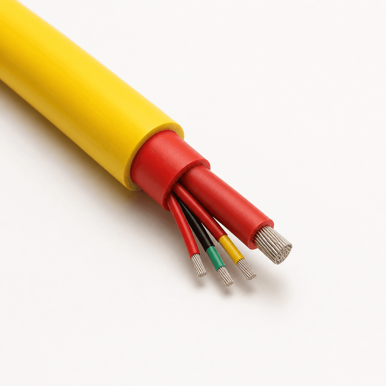
These values demonstrate why actual product data is preferable to an assumed resistance. They do not mean that every 28 V project should use 120 mm² or six 40 mm² conductors. The current path, cable length, continuous and peak current, control architecture, connector, movement and allowable terminal voltage must all be confirmed.
Why 28 V systems often need large flexible conductors
Delivering substantial power at 28 V requires high current. A larger conductor lowers resistance, but it also increases cable diameter, copper mass, bending force and termination size. A ground-power cable must therefore balance electrical loss with flexibility, handling, wear resistance and connector compatibility.
48 V DC Cable Voltage Drop and Sizing
For the same absolute voltage loss, a 48 V system is less percentage-sensitive than 12 V, 24 V or 28 V. It may also carry less current than a lower-voltage system delivering the same power. Neither point removes the need for calculation.
If a 48 V load draws 40 A and the total loop resistance is 0.060 Ω, the drop is 2.40 V, or 5.0%, leaving 45.60 V at the load. The correct response might be a larger conductor, shorter route or different system design—but only after confirming the load’s permitted voltage range and all installation constraints.
270 V DC Cable Voltage Drop for Aircraft Ground Power
A 2 V loss is a smaller percentage of 270 V than of 28 V, but absolute drop still depends on current, conductor resistance and circuit length. The cable also has to satisfy voltage rating, power and control architecture, connector interface, mechanical movement and the operating environment.
The published 270V DC aircraft ground power cable combines 8 AWG power conductors and 14 AWG control conductors in a multi-core construction with PUR sheath layers and an aramid supporting braid. Its configuration should be reviewed against the actual ground-support system; a 24 V or 28 V conductor arrangement should not be transferred to 270 V by assumption.
12 V vs 24 V vs 28 V vs 48 V vs 270 V
| DC system | Relative sensitivity to the same voltage loss | Relevant industrial context |
|---|---|---|
| 12 V | Very high | Low-voltage DC equipment |
| 24 V | High | Industrial control and field equipment |
| 28 V | High | Aircraft ground power |
| 48 V | Moderate | Industrial and mobile DC systems |
| 270 V | Lower percentage for the same lost volts | Aircraft DC ground power |
This is a relative comparison, not a conductor-size table. Current, power, length, equipment tolerance, cable construction and operating temperature must still be calculated for each project.
How Cable Length Changes DC Voltage Drop
In a simple DC circuit, voltage drop increases approximately in proportion to conductor length when current, conductor material, cross-section and temperature remain unchanged.
| One-way length | Relative voltage drop |
|---|---|
| 5 m | 1× |
| 10 m | 2× |
| 20 m | 4× |
| 50 m | 10× |
Avoid unnecessary routing, but do not remove service loops or movement allowance needed for safe operation. Real installed length takes priority over the shortest geometric path.
How Conductor Size Changes DC Voltage Drop
Resistance is inversely related to conductor area in the simplified resistivity model. With material, length and temperature unchanged, increasing cross-section reduces resistance and voltage drop.
| Nominal conductor size | Relative resistance | Relative DC voltage drop |
|---|---|---|
| 10 mm² | Higher | Higher |
| 25 mm² | Lower than 10 mm² | Lower than 10 mm² |
| 50 mm² | Lower than 25 mm² | Lower than 25 mm² |
| 120 mm² | Lowest in this comparison | Lowest in this comparison |
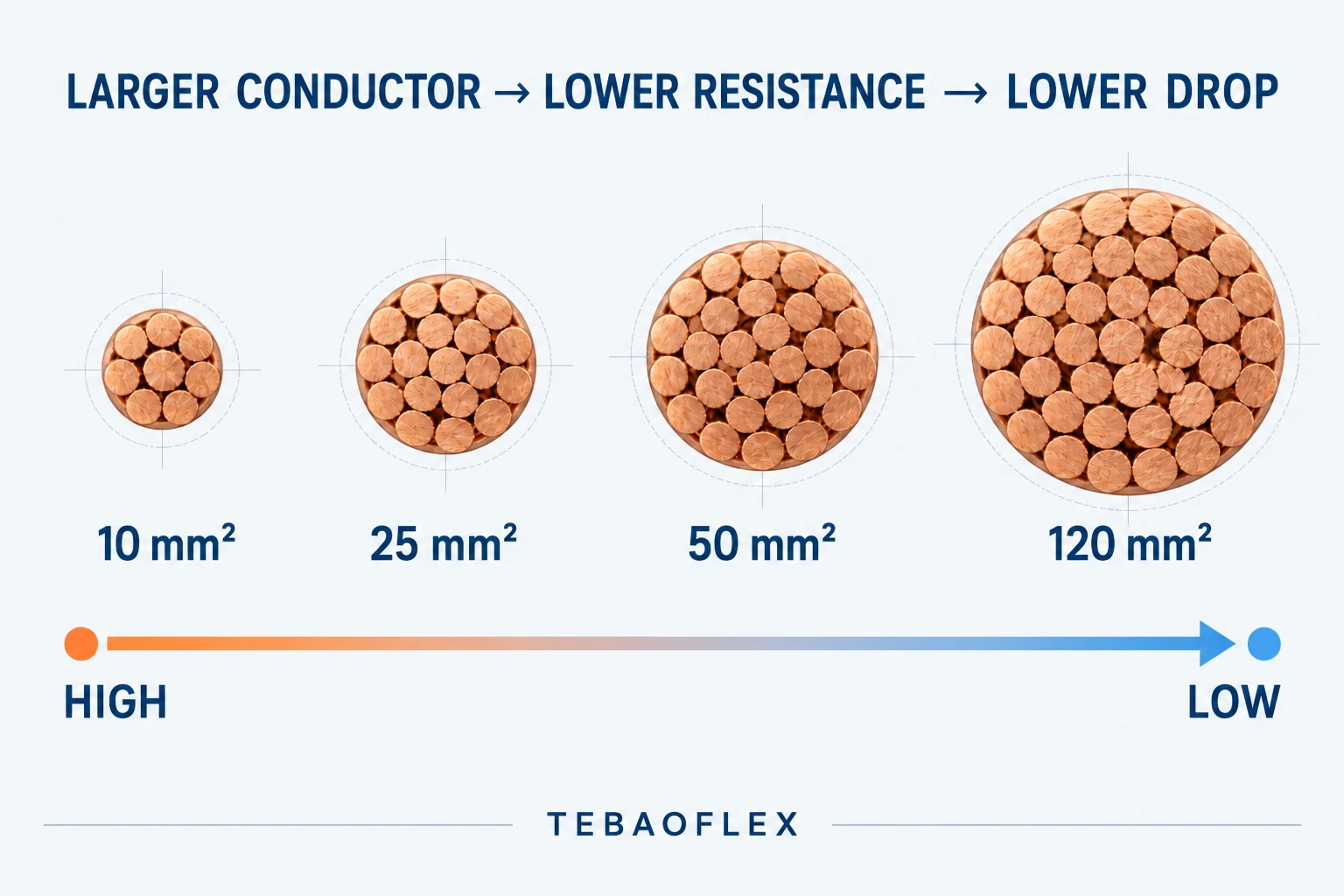
Do not infer current rating or a project recommendation from this relative table. Review the complete industrial cable selection guide before finalizing construction and size.
Why Ampacity Alone Is Not Enough for DC Cable Sizing
A cable may be thermally capable of carrying the design current and still deliver too little voltage after a long route. Ampacity evaluates conductor temperature under defined installation conditions. Voltage drop evaluates voltage available at the load. Short-circuit withstand, protective-device operation and mechanical suitability are additional checks.
Use the cable ampacity calculation process together with voltage-drop analysis. Neither check replaces the other.
DC Cable Size in mm² vs AWG
Metric cable specifications commonly use mm², while North American designs use AWG or kcmil. These systems are not interchangeable labels. Compare actual conductor area, resistance, stranding, ampacity conditions and termination compatibility rather than selecting the nearest-looking number.
The 28 V products above use metric power-core sizes, while the published 270 V configuration uses AWG sizes. Our AWG to mm² conductor size guide supports initial comparison, but verified product data remains the design input.
How Temperature Affects DC Voltage Drop
Copper resistance increases as conductor temperature rises, so a 20°C resistance value cannot automatically represent operation at 70°C or 90°C. The Copper Development Association’s installation guidance identifies temperature as a major factor in conductor resistance and voltage drop. Use the correction method required by the applicable data source and project.
DC Voltage Drop and Power Loss
Voltage drop also represents energy converted to heat in the resistive path. The resistive cable loss is:
Ploss = I²R
Doubling current multiplies resistive loss by four when resistance is unchanged. This is one reason low-voltage, high-power DC systems can require large conductors and careful connection design.
How to Reduce Voltage Drop in a DC Cable
Increase conductor cross-section
A larger conductor usually provides the most direct resistance reduction. Confirm that cable diameter, weight, bending radius and terminations remain practical.
Reduce cable length where possible
Position sources and distribution points closer to high-current loads and avoid unnecessary routing, while retaining required travel and service allowance.
Use low-resistance conductors and connections
Confirm cable material, lugs, connectors, contacts and joint quality. A suitable cable cannot compensate for a damaged, loose or undersized connection.
Use parallel conductors only when properly engineered
Parallel paths require appropriate conductor matching, routing, protection, terminations and current sharing. Do not add parallel conductors as an informal field remedy.
Increase system voltage only when the architecture permits it
A higher system voltage can reduce current for the same power, but changing voltage affects the equipment, controls, protection, connectors, cable rating and safety design. It is a system-level decision, not a cable-sizing shortcut.
DC Voltage Drop in Flexible and Moving Cables
Aircraft ground power, mobile equipment, reels and drag chains add mechanical constraints to the electrical calculation. Increasing conductor size can raise cable outside diameter, weight, minimum bending radius, handling force and connector requirements. Fine stranding, reinforcement, sheath material, travel speed and duty cycle must be considered with resistance and ampacity.
A flexible single-conductor power cable such as the published DLO construction can illustrate the availability of heavy-current flexible conductor sizes, but DLO is not automatically a dedicated 12 V, 24 V or 28 V cable. Its voltage rating, marking, installation method and project compliance must match the application. For moving machinery, use the mobile equipment cable selection checklist as an additional review.
When a Simple DC Formula Is Not Enough
A single V, A, m and mm² calculation is not a complete design when the system includes:
- battery voltage that changes with state of charge or load;
- starting, inrush or cyclic peak current;
- parallel conductors or multiple distributed loads;
- connectors, contactors and joints with meaningful resistance;
- long cable assemblies operating at elevated temperature;
- ground-return or non-standard current paths;
- aircraft ground-power interfaces with combined power and control cores;
- protection requirements that depend on available fault current.
Model the actual operating states, verify the cable and connection data, and coordinate the result with the equipment supplier and the applicable engineering requirements.
DC Cable Selection Checklist
| Parameter | What to provide |
|---|---|
| System voltage | 12, 24, 28, 48 or 270 V DC; include operating range |
| Continuous current | Design current in A |
| Peak or starting current | Current in A and duration/duty cycle |
| One-way cable length | Actual routed length in m |
| Target terminal voltage or drop | Minimum load voltage, V or % |
| Conductor system | Required mm², AWG or kcmil convention |
| Movement | Fixed, trailing, reel, drag chain or mobile handling |
| Environment | Temperature, oil, fuel, UV, water, abrasion and other exposure |
| Connector | Model, interface and termination limits |
| Compliance | Destination market, standard and documentation requirements |
Frequently Asked Questions
1. How do you calculate voltage drop in a DC cable?
Use ΔV = I × Rloop. For a simple two-wire circuit, ΔV = 2IRL when R is one-conductor resistance per unit length and L is one-way length. A resistivity estimate is ΔV = 2IρL/A.
2. Why is cable length doubled in DC calculations?
A conventional two-wire circuit has an outgoing and a return conductor, so the electrical path is approximately twice the one-way route. Use the real current path for other architectures.
3. What cable size do I need for a 24 V DC system?
There is no fixed size based on voltage alone. Required size depends on current, length, allowed drop, conductor temperature, installation method, duty and equipment limits.
4. Why is voltage drop more important in 12 V and 24 V systems?
The same number of lost volts is a larger percentage of a low supply voltage. A 2 V loss is 16.7% of 12 V but only 0.74% of 270 V.
5. Does increasing cable size reduce DC voltage drop?
Yes, when material, length, current and temperature remain unchanged. A larger cross-section lowers resistance, but mechanical and termination constraints must also be checked.
6. What is different about 24 V and 48 V cable sizing?
For the same delivered power, a 48 V system generally draws less current than a 24 V system, which can reduce voltage drop and I²R loss. Actual cable size must still be recalculated from the real load and route.
7. How is a 28 V aircraft ground power cable sized?
Confirm GPU current, peak duty, route length, allowed terminal voltage, conductor resistance, connector, movement, temperature and cable architecture. Do not assume one conductor size fits both SC and SF configurations.
8. Does a 270 V cable have less voltage drop than a 28 V cable?
System voltage alone does not determine absolute voltage drop. Drop depends on current, resistance and circuit length. The same absolute loss is, however, a much smaller percentage of 270 V than of 28 V.
Need Help Sizing a DC Power Cable?
Send TEBAOFLEX your DC system voltage, continuous and peak current, one-way cable length, target terminal voltage or voltage drop, conductor-size convention, movement type, connector requirements and operating environment. Our team can review the electrical inputs together with the mechanical cable requirements for your application.
Technical basis: Calculations in this guide are illustrative and are intended to show method and sensitivity. Product construction and resistance values are taken from the linked TEBAOFLEX product pages. Conductor resistance requirements and temperature correction should be checked against the applicable conductor standard, verified cable data and the project’s adopted rules.