Why Cable Size Selection Matters
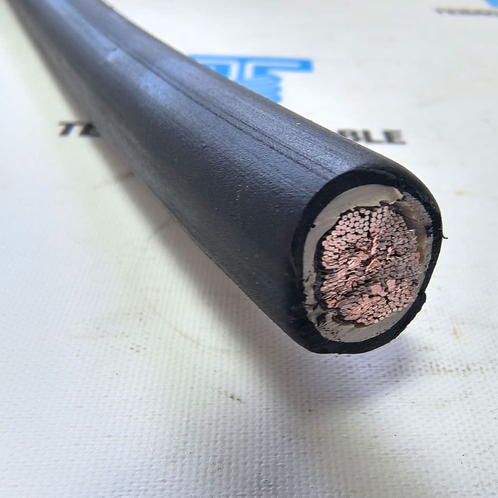
Selecting the correct cable cross-section (conductor size) is one of the most fundamental decisions in electrical design. An undersized cable overheats, degrades prematurely, and creates fire and safety hazards. An oversized cable adds unnecessary cost, weight, and installation complexity. The right size balances safety, performance, and economics.
This cable size and cross-section selection guide explains how to determine the right conductor size for any application, covering ampacity, voltage drop, short-circuit withstand, and the IEC and AWG sizing systems. TEBAOFLEX provides free cable sizing assistance — contact our engineering team for project-specific recommendations.
Cable Size Standards: IEC mm² vs AWG
Two main sizing systems are used worldwide:
IEC Metric System (mm²)
Used in Europe, Asia, Middle East, Africa, and most of the world. Conductor cross-sectional area is specified in square millimeters (mm²).
Standard IEC sizes: 0.5, 0.75, 1, 1.5, 2.5, 4, 6, 10, 16, 25, 35, 50, 70, 95, 120, 150, 185, 240, 300, 400, 500, 630, 800, 1000 mm²
AWG / kcmil System (North America)
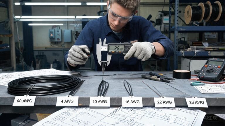
Used in the United States, Canada, and some Latin American countries. The American Wire Gauge (AWG) system is logarithmic — smaller gauge numbers mean larger conductors. Above 4/0 AWG, sizes are specified in kcmil (thousand circular mils).
Common sizes: 18, 16, 14, 12, 10, 8, 6, 4, 2, 1, 1/0, 2/0, 3/0, 4/0 AWG, then 250, 300, 350, 400, 500, 600, 750, 1000 kcmil
IEC mm² to AWG Approximate Conversion
| IEC (mm²) | AWG / kcmil | Approx. OD (mm) |
|---|---|---|
| 0.5 | 20 AWG | 0.8 |
| 0.75 | 18 AWG | 1.0 |
| 1.0 | 17 AWG | 1.1 |
| 1.5 | 16 AWG (close) | 1.4 |
| 2.5 | 14 AWG (close) | 1.8 |
| 4.0 | 12 AWG (close) | 2.3 |
| 6.0 | 10 AWG (close) | 2.8 |
| 10 | 8 AWG (close) | 3.6 |
| 16 | 6 AWG | 4.5 |
| 25 | 4 AWG | 5.6 |
| 35 | 2 AWG | 6.7 |
| 50 | 1 AWG | 8.0 |
| 70 | 2/0 AWG | 9.4 |
| 95 | 3/0 AWG | 11.0 |
| 120 | 4/0 AWG | 12.4 |
| 185 | 250 kcmil | 15.4 |
| 240 | 350 kcmil | 17.5 |
| 300 | 400 kcmil | 19.5 |
| 400 | 600 kcmil | 22.6 |
| 500 | 750 kcmil | 25.2 |
Note: IEC and AWG sizes are not exactly equivalent — always use the actual cross-sectional area for calculations, not approximate gauge comparisons.
Step-by-Step Cable Size Selection
Step 1: Determine Load Current
Calculate the full-load operating current of the circuit:
- Three-phase: I = P / (√3 x V x PF x η)
- Single-phase: I = P / (V x PF x η)
- DC: I = P / V
Where P = power (W), V = voltage (V), PF = power factor, η = efficiency.
For motor circuits, use the motor nameplate full-load current (FLA), not calculated current. Consider the motor service factor (SF) and starting current.
Step 2: Select Insulation Temperature Rating
Common insulation temperature ratings:
- PVC 70°C: general purpose, lower cost
- PVC 90°C: higher ampacity, building wire
- XLPE 90°C: standard for power cables (LV and MV)
- EPR 90°C: flexible, water-resistant (mining, marine)
- Rubber 60°C / 75°C: older types, less common now
Higher temperature ratings allow higher ampacity for the same conductor size. However, the terminal temperature rating (often 70°C or 75°C) may limit the usable ampacity even if the cable insulation is rated higher.
Step 3: Determine Installation Conditions
- Installation method: free air, cable tray, conduit, direct burial
- Ambient temperature: maximum expected operating temperature
- Grouping: number of cables installed together
- Soil conditions (if buried): thermal resistivity, moisture content
For detailed ampacity derating, see our cable ampacity guide.
Step 4: Apply Derating Factors and Select Size
Derate the base ampacity from tables by multiplying by all applicable correction factors:
Allowable Ampacity = Base Ampacity x Temp Factor x Grouping Factor x Installation Factor
Select the smallest conductor size where the allowable (derated) ampacity is greater than the design current.
Step 5: Check Voltage Drop
Calculate voltage drop for the cable length:
- DC: Vd = 2 x I x L x R / A
- Single-phase AC: Vd = 2 x I x L x (R x cosφ + X x sinφ) / A
- Three-phase AC: Vd = √3 x I x L x (R x cosφ + X x sinφ) / A
Where I = current (A), L = length (m), R = resistivity (Ω x mm²/m), X = reactance (Ω/km), A = cross-section (mm²).
Copper resistivity: ~0.0172 Ω x mm²/m at 20°C, ~0.021 Ω x mm²/m at 90°C
Aluminum resistivity: ~0.0282 Ω x mm²/m at 20°C, ~0.034 Ω x mm²/m at 90°C
Typical voltage drop limits:
- Power circuits: 3-5% from supply point to load
- Motor circuits: 3% full-load, 15% starting (or per manufacturer limit)
- Control circuits: 2-3% to ensure relay/contactor operation
- Lighting: 2-3% to prevent visible flicker
If voltage drop is too high, increase the conductor size and recalculate.
Step 6: Verify Short-Circuit Withstand
Using the adiabatic equation:
A_min = I_sc x √t / k
Where I_sc = short-circuit current (A), t = clearing time (s), k = constant (copper XLPE: ~143, copper PVC 70°C: ~115, aluminum XLPE: ~94).
The minimum conductor size must be greater than A_min to withstand the fault current without damage.
Step 7: Consider Future Growth
Add a safety margin for future load increases. A 20-30% margin is common practice. In industrial plants where production capacity may expand, sizing up one or two sizes can save the cost of cable replacement later.
Typical Cable Size Applications
Control and Signal Cables (Small Sizes)
| Size (mm²) | Approx. Ampacity (A) | Typical Applications |
|---|---|---|
| 0.5 | 6-10 | Instrumentation, low-level signals, sensor cables |
| 0.75 | 10-14 | Control circuits, relay wiring, small signal cables |
| 1.0 | 12-16 | Control circuits, small motors (≤0.25kW) |
| 1.5 | 16-20 | Lighting circuits, control cables, small motors |
| 2.5 | 22-27 | Lighting, small power, motors up to 2.2kW |
| 4.0 | 28-35 | Power circuits, motors up to 5.5kW |
Power Cables (Medium to Large Sizes)
| Size (mm²) | Approx. Ampacity (A) | Typical Applications |
|---|---|---|
| 6 | 35-45 | Motors up to 11kW, sub-main distribution |
| 10 | 50-65 | Motors up to 18.5kW, sub-main feeders |
| 16 | 70-90 | Motors up to 30kW, distribution feeders |
| 25 | 100-125 | Motors up to 55kW, main distribution |
| 35 | 125-160 | Motors up to 75kW, large feeders |
| 50 | 155-200 | Motors up to 110kW, main feeders |
| 70 | 200-260 | Motors up to 160kW, substation feeders |
| 95 | 250-320 | Motors up to 200kW, large distribution |
| 120 | 290-370 | Motors up to 250kW, busbar connections |
| 150 | 340-430 | Large motors, transformer feeders |
| 185 | 390-490 | Transformer feeders, main incoming cables |
| 240 | 460-570 | Large transformer feeders, bus risers |
| 300 | 530-660 | Very large transformers, parallel circuits |
| 400 | 620-770 | Extra large feeders, parallel circuits |
Note: These are approximate values for copper XLPE 90°C in free air. Actual ampacity varies significantly with installation method, ambient temperature, and grouping. Always calculate derated ampacity for specific conditions.
Copper vs Aluminum Size Selection
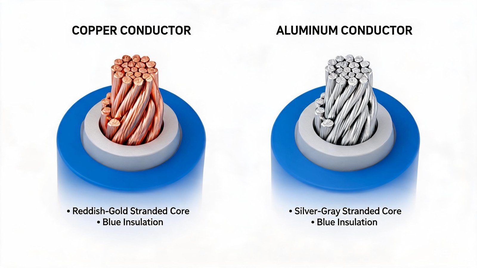
Because aluminum has lower conductivity (~61% IACS vs 100% for copper), aluminum cables must be larger to carry the same current:
- An aluminum cable needs approximately 1.6x the cross-sectional area of a copper cable for the same ampacity
- Example: 120mm² copper ≈ 185mm² aluminum (similar current capacity)
- Aluminum has higher voltage drop for the same size due to higher resistance
- Aluminum is lighter (3.3x lighter by weight) and typically lower cost
Aluminum is generally more economical for large feeders and MV cables (95mm² and above). Copper is preferred for smaller sizes, flexible cables, and where terminations are simpler.
For a detailed comparison, see our copper vs aluminum conductor guide.
Parallel Cables: When to Use Multiple Cables in Parallel
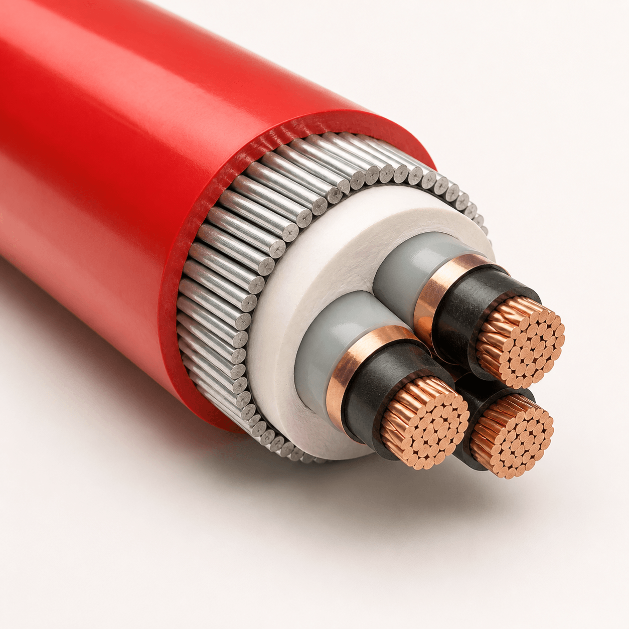
For very high currents, using multiple smaller cables in parallel may be more practical than a single very large cable:
- Easier installation: Smaller cables are lighter and easier to handle, pull, and terminate
- Availability: Very large cable sizes (above 300-400mm²) may have longer lead times
- Cost: Parallel cables can be more cost-effective than a single very large cable
- Reliability: If one cable fails, the remaining cables may carry the load (if sized for N-1)
Important considerations for parallel cables:
- Cables must be identical: same type, size, length, and manufacturer
- Terminations must be identical to ensure equal current sharing
- Cables must be routed similarly to maintain equal impedance
- Derating applies: grouped parallel cables reduce individual ampacity
- Short-circuit current divides among parallel cables
- Unbalanced current sharing can cause overheating of individual cables
Common Sizing Mistakes
- Using nameplate kW/kVA directly: Always calculate actual current considering power factor, efficiency, and voltage
- Forgetting derating factors: Real-world installation conditions almost always reduce ampacity below table values
- Ignoring voltage drop: Long runs often require larger sizes than ampacity alone suggests
- Neglecting short-circuit rating: Small conductors can be damaged by high fault currents even if they carry the normal current fine
- Using the wrong ambient temperature: Cables in hot environments (engine rooms, foundries, desert climates) need higher temperature-rated insulation or larger sizes
- Not allowing for future growth: Adding a size or two now saves much more in replacement cost later
- Assuming aluminum and copper are interchangeable by size: Different conductivity means different sizes are needed
- Ignoring harmonics: Nonlinear loads (VFDs, UPS) increase current and heating, requiring larger cables
TEBAOFLEX Cable Sizing Support
TEBAOFLEX provides comprehensive cable sizing and selection support:
- Free cable sizing calculations for your specific application
- Ampacity and voltage drop analysis per IEC, NEC, or project standards
- Short-circuit withstand verification
- Copper vs aluminum comparison and recommendations
- Parallel cable feasibility studies
- Technical support for complex cable systems
Need help selecting the right cable size? Contact TEBAOFLEX engineering with your project details for a professional cable sizing recommendation and quotation.
Request a Quote
Submit your cable requirements — including load current, voltage, cable length, installation method, and environment — and our technical team will recommend the correct conductor size and cable type with pricing. Request your cable sizing consultation and quotation.