Cable length directly affects voltage drop because conductor resistance increases as the current path becomes longer. If current, conductor material and cross-sectional area remain unchanged, increasing cable length increases circuit resistance and therefore increases voltage drop.
This is why a cable size that is adequate for a 20 m run may not be suitable for the same load at 100 m or 200 m, even when the cable still has sufficient ampacity. For fixed and moving industrial cables, the final decision must balance electrical performance with cable diameter, weight, bending radius, termination size and mechanical duty.
| If cable length changes | Resistance | Voltage drop | Likely sizing impact |
|---|---|---|---|
| Length increases | Increases | Increases | A larger conductor may be required |
| Length decreases | Decreases | Decreases | The existing conductor may be sufficient |
| Length doubles | Approximately doubles* | Approximately doubles* | Recheck conductor size |
| Conductor size increases | Decreases | Decreases | Cable OD and weight also increase |
*This proportional relationship assumes the same current, conductor material, conductor size, temperature and relevant circuit conditions.
Does Cable Length Affect Voltage Drop?
Yes. A longer current path contains more conductor, so its total resistance is higher. At the same current, Ohm’s Law then produces a larger voltage drop and a lower voltage at the load:
Cable length ↑ → circuit resistance ↑ → voltage drop ↑ → load voltage ↓
Length is only one input. Conductor area, material, temperature, current, AC reactance, power factor and connection resistance can also change the result. For the underlying resistance model, see our cable resistance formula. For complete DC, single-phase and three-phase equations, use the cable voltage drop calculation guide.
Why Does a Longer Cable Have More Resistance?
The simplified conductor relationship is:
R = ρL / A
- R is conductor resistance.
- ρ is material resistivity.
- L is conductor length.
- A is conductor cross-sectional area.
When ρ and A remain unchanged, resistance is proportional to length: R ∝ L. The relationship is simple, but the input data still matters. Actual cable resistance should come from verified product or conductor data at the relevant operating temperature. IEC 60228:2023 covers nominal conductor cross-sections and resistance requirements for several conductor classes, including flexible copper conductors.
What happens if cable length doubles?
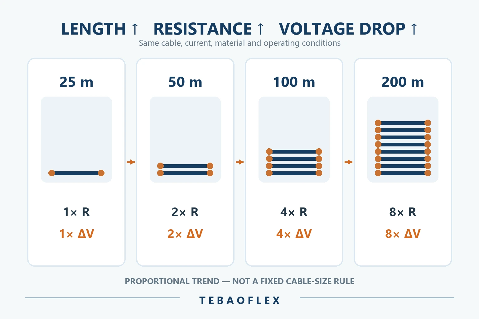
In the simplified case, doubling length approximately doubles total resistance. If current is also unchanged, voltage drop approximately doubles. A fourfold length produces roughly four times the resistance and voltage drop.
| One-way cable length | Relative resistance | Relative voltage drop |
|---|---|---|
| 25 m | 1× | 1× |
| 50 m | 2× | 2× |
| 100 m | 4× | 4× |
| 200 m | 8× | 8× |
Cable Length vs Circuit Length
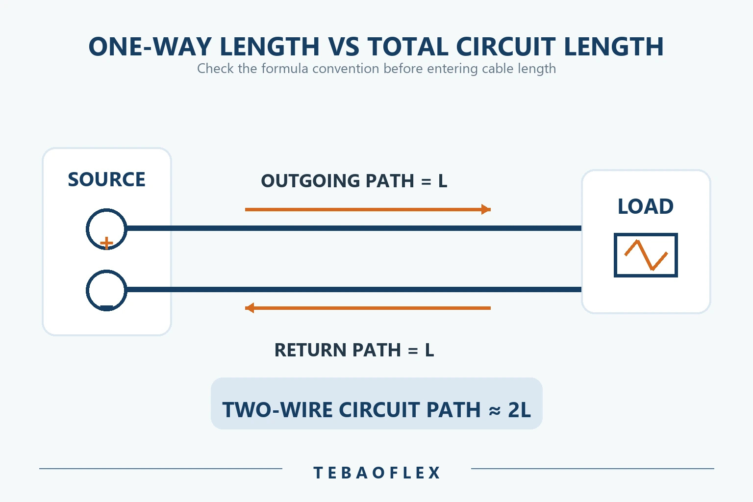
A frequent calculation error is entering the wrong length. The distance from the source to the equipment is the one-way route length. The total current path may include an outgoing and a return conductor.
One-way cable length
If equipment is 100 m from the source along the installed route, the one-way length is 100 m. Use the actual routed distance through trays, reels, festoon loops, structures and service allowances—not the straight-line map distance.
Total circuit length
In a simple two-wire DC circuit, a 100 m outgoing conductor plus a 100 m return conductor gives approximately 200 m of total conductor path. Some formulas use one-way length and include a factor of 2; other methods use the full loop resistance. Single-phase and three-phase conventions also differ.
How Cable Length Affects Voltage Drop
Voltage drop follows the basic relationship ΔV = I × R. If the same cable carries the same current, a longer route increases R and therefore ΔV. The load receives the source voltage minus this drop.
This proportional rule is useful for sensitivity checks, but it does not replace a design calculation. In AC circuits, resistance, reactance and power factor matter. Conductor temperature changes resistance. Motor starting current can make a transient check more restrictive than normal running conditions. The allowable result must come from the connected equipment, project specification and rules adopted for the installation. IEC 60364-5-52 addresses the selection and erection of low-voltage wiring systems, including voltage-drop considerations; use the edition and national implementation applicable to the project.
Cable Length vs Cable Size
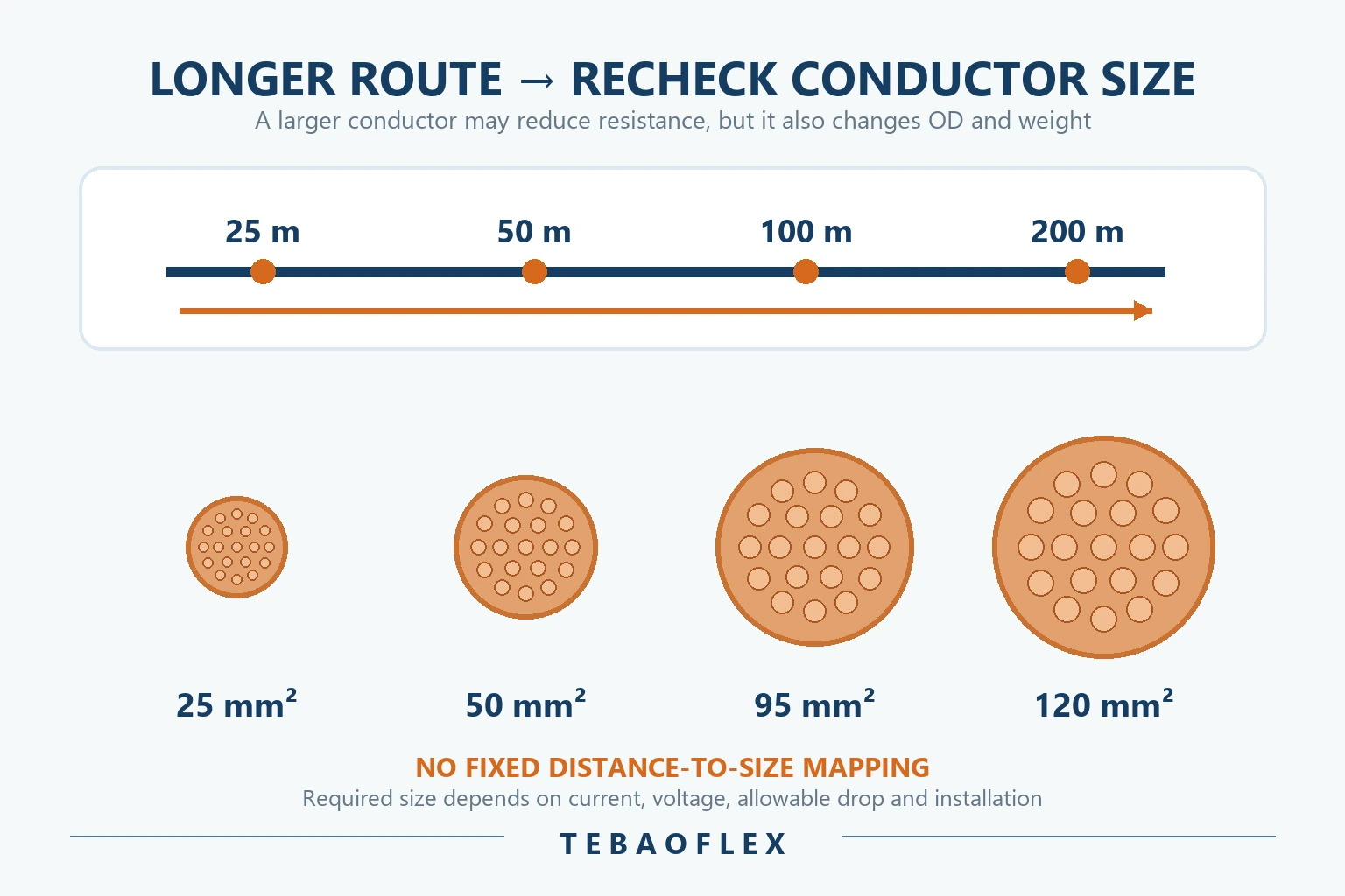
When additional length raises resistance, increasing conductor area can reduce it because R = ρL/A. That is why distance can change the conductor size even when the load current has not changed.
Short, medium and long runs are relative terms
A 20–30 m route might allow one candidate cable to pass both ampacity and voltage-drop checks. At 50–100 m, the same cable may remain thermally adequate while voltage drop becomes the controlling factor. At 100–200 m or more, a larger conductor or a system-level review may be necessary.
These distance bands are examples for explanation, not standard definitions. Whether a route is electrically “long” depends on voltage, current, cable impedance, load behaviour and allowed terminal voltage. Follow the complete cable size and cross-section selection process.
Worked Example: Same Load, Different Cable Lengths
Consider an illustrative 400 V balanced three-phase industrial load drawing 80 A at power factor 0.85. Assume the selected cable data at the design temperature gives R = 0.55 Ω/km and X = 0.08 Ω/km. Only the one-way route length changes.
| One-way length | Calculated voltage drop | Drop as % of 400 V | Relative result |
|---|---|---|---|
| 25 m | 1.77 V | 0.44% | 1× |
| 50 m | 3.53 V | 0.88% | 2× |
| 100 m | 7.06 V | 1.77% | 4× |
| 200 m | 14.12 V | 3.53% | 8× |
The result uses the same cable, current, power factor and operating data throughout, so doubling the distance doubles the calculated drop. The 200 m result is not automatically acceptable or unacceptable; it must be compared with the equipment and project limit. The key selection lesson is that a cable chosen for 25 m cannot be carried over to 200 m without recalculation.
Worked Example: Same Length, Different Conductor Sizes
Now keep the same 400 V, 80 A, 0.85 power-factor load and a 100 m one-way route. The table uses illustrative operating-temperature resistance values and the same X = 0.08 Ω/km to show how lower resistance changes the result. It is not a cable-size recommendation.
| Illustrative conductor size | Illustrative R | Voltage drop | Drop % | Mechanical trend |
|---|---|---|---|---|
| 25 mm² | 0.90 Ω/km | 11.18 V | 2.80% | Lower OD and weight |
| 35 mm² | 0.65 Ω/km | 8.24 V | 2.06% | OD and weight increase |
| 50 mm² | 0.48 Ω/km | 6.24 V | 1.56% | OD and weight increase |
| 70 mm² | 0.35 Ω/km | 4.71 V | 1.18% | Highest OD and weight in this comparison |
Use the specified cable’s verified R and X values for a real design. Nominal cross-section alone does not guarantee the exact resistance assumed above, and the final size must also pass ampacity, fault, protection, installation and mechanical checks.
Why a Larger Cable Is Not Always a Free Solution
“Use a bigger cable” is incomplete advice. For a fixed feeder, the additional diameter and cost may be manageable. In a moving cable system, upsizing can materially change:
- outside diameter and cable weight;
- minimum bending radius and drum diameter;
- festoon trolley load and loop geometry;
- suspended weight in vertical travel;
- termination and connector size;
- pulling force, tensile loading and acceleration;
- drum capacity and equipment handling force.
Electrically larger is not automatically mechanically better. A long moving route requires electrical and mechanical cable design to be checked together.
Cable Length and Ampacity Are Different Checks
| Question | Ampacity | Voltage drop |
|---|---|---|
| Does route length by itself define the basic thermal current rating? | No | Not applicable |
| Does length affect total circuit resistance? | Indirectly relevant to losses | Yes |
| Can a cable pass ampacity but fail voltage drop? | Yes | Yes |
| Can a long run require a larger conductor? | Yes, after the full design review | Yes |
Cable length does not automatically reduce a conductor’s published ampacity, but a longer run can require a larger conductor because of voltage drop and system-performance limits. Installation method, ambient temperature, grouping and duty still determine the thermal result. See the cable ampacity calculation guide.
Cable Length and Power Loss
Longer cable also increases resistive loss when current is unchanged:
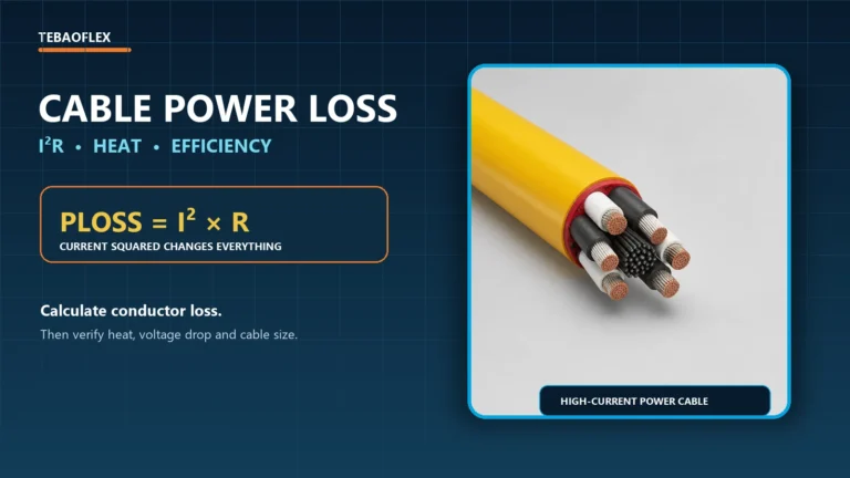
Ploss = I²R
Voltage drop and power loss are different outputs, but both depend on conductor resistance. Higher resistance means more voltage is lost along the route and more electrical energy is converted to heat. Temperature can then raise copper resistance further, which is why room-temperature values should not automatically be used for a hot operating conductor. The Copper Development Association’s recommended copper-wire installation practices discuss the effect of length and temperature on resistance and voltage drop.
Cable Length in DC and AC Systems
DC cable runs
DC calculations commonly focus on resistance and the complete outgoing-and-return current path. Low-voltage DC systems can be particularly percentage-sensitive. See the dedicated DC cable voltage drop guide for 12 V through 270 V applications.
Single-phase AC cable runs
Single-phase calculations include the outgoing and return paths and may require resistance, reactance and power factor. Check whether the selected formula expects one-way or total circuit length.
Three-phase cable runs
Balanced three-phase voltage drop uses a different expression from DC and single-phase circuits. Length remains important, but the circuit convention and cable R/X data must match the system.
When Long Runs Need More Than a Larger Conductor
For very long routes, large loads, motors, VFD systems, mining equipment or mobile cranes, continually increasing conductor size may become mechanically or economically impractical. System designers may need to evaluate source location, transformer position, distribution voltage, drive arrangement, parallel circuits or other architecture.
These are system-level decisions. They should never be changed solely because one voltage-drop calculation is high.
When medium voltage may be part of the original design
High-power mobile equipment can use medium-voltage distribution as part of its engineered architecture. The published (N)TSCGEWÖU MT medium-voltage reeling cable covers 3.6/6 kV through 12/20 kV configurations for mining, port and heavy-industrial reeling applications. This is an example of a product family for an already-designed MV system—not a recommendation to convert a low-voltage installation because its cable is long.
Cable Length in Reeling and Festoon Systems
In fixed wiring, installed route length may be close to the measured tray or conduit route. In reeling, festoon and spreader systems, equipment travel distance is not the same as electrical cable length. The total requirement may include hanging loops, drum reserve, terminal allowance, service loops, vertical travel and the geometry of the mechanical arrangement.

The (N)GRDGOEU flexible festoon power cable is published in single-core power sizes from 25 mm² to 240 mm² and in multi-core power/control configurations. Its selection also involves movement speed, tensile loading, bending radius and equipment layout. When cross-section changes to control voltage drop, those mechanical parameters must be reviewed again.
Cable Length in Vertical Reeling Applications
On a mobile harbour crane or spreader basket, a long vertical cable can carry part of its own suspended mass. Increasing conductor size reduces electrical resistance but increases the cable weight that the reeling and support system must manage.
The published vertical reeling cable for port cranes uses an aramid self-supporting element and braid reinforcement for vertical reeling duty. Its project review requires suspension height, routing geometry, load, acceleration and electrical requirements. This illustrates why conductor upsizing cannot be separated from the vertical mechanical calculation.
How to Select Cable Size for a Long Run
- Define system voltage, phase arrangement and frequency.
- Confirm continuous, peak and starting current.
- Measure the actual one-way route, including movement and service allowances.
- Select a candidate conductor size and cable construction.
- Obtain resistance and, for AC, reactance at the relevant operating conditions.
- Calculate voltage drop using the correct length convention.
- Compare load voltage with the equipment and project requirement.
- If the drop is excessive, evaluate a larger conductor or system-level option.
- Recheck ampacity, fault withstand and protective-device operation.
- Recheck cable OD, weight, bending radius and termination compatibility.
- For moving cable, recheck tensile load, reel capacity, festoon geometry and duty cycle.
Use the industrial cable selection guide and the mobile equipment cable selection checklist to complete the review. For projects using AWG or kcmil, consult the AWG and mm² cable size guide.
Common Cable Length and Voltage Drop Mistakes
| Mistake | Why it matters | Correct approach |
|---|---|---|
| Using straight-line distance | Understates the installed route | Measure the complete routed path |
| Doubling length when the formula already includes the return path | Overstates voltage drop | Check the formula convention |
| Forgetting the return conductor | Understates loop resistance | Model the actual current path |
| Selecting by ampacity only | A thermally adequate cable may deliver insufficient voltage | Check ampacity and voltage drop separately |
| Using 20°C resistance for a hot conductor | Can understate operating resistance | Use corrected or verified design-temperature data |
| Ignoring reactance and power factor in AC systems | Can distort long-feeder results | Use appropriate R, X and power-factor inputs |
| Upsizing without a mechanical review | May exceed reel, trolley, bend or termination limits | Recheck electrical and mechanical design together |
Frequently Asked Questions
1. Does cable length affect voltage drop?
Yes. A longer conductor has more total resistance, so voltage drop increases when current and the other cable conditions remain unchanged.
2. Does doubling cable length double voltage drop?
Approximately yes in the simplified case where current, conductor material, cross-section, temperature and circuit conditions stay the same.
3. Why do longer cable runs need larger conductors?
A larger cross-section lowers resistance per unit length and can offset part of the resistance added by a longer route.
4. How does cable length affect cable size?
Length does not define one fixed size. It changes resistance and voltage drop, which may make a larger conductor necessary after current, voltage, temperature and installation conditions are checked.
5. Does cable length affect ampacity?
Length does not by itself define conductor ampacity. A long run may nevertheless require a larger conductor because of voltage drop, losses or equipment-performance requirements.
6. Should cable length be measured one way or round trip?
It depends on the formula and resistance input. Confirm whether the method expects one-way length, total circuit length or a complete loop resistance before calculating.
7. How can I reduce voltage drop in a long cable run?
Possible engineering options include a larger conductor, a shorter route, lower current or a different distribution architecture. Each option must be reviewed against the complete system design.
8. Is a larger cable always better for a long run?
No. Electrical resistance falls, but diameter, weight, bending radius, termination size and moving-system loads increase. The best cable satisfies both electrical and mechanical requirements.
Need Help Sizing Cable for a Long Run?
Send TEBAOFLEX your system voltage, load current, one-way route length, allowable voltage drop, candidate conductor size, installation arrangement and movement requirements. For reeling, festoon or vertical applications, also provide travel distance, speed, bending arrangement, suspension height and tensile conditions so the electrical and mechanical requirements can be reviewed together.
Technical note: The worked examples illustrate how distance and conductor resistance change a result. They are not cable recommendations. Final selection must use verified cable data, the actual circuit arrangement, operating temperature, equipment limits and the standards adopted for the project.