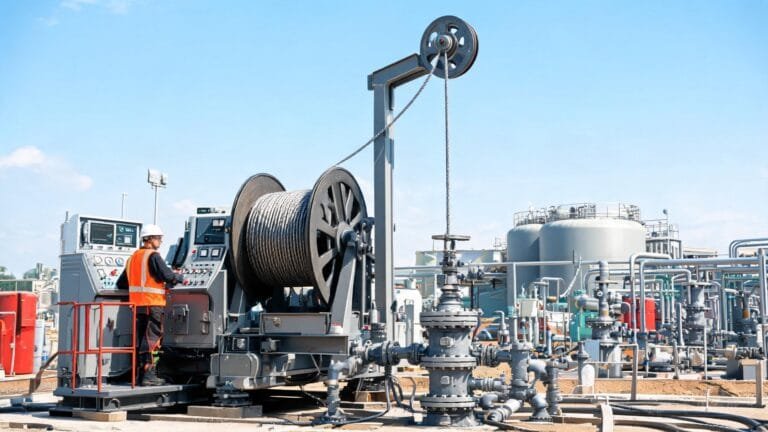
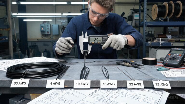
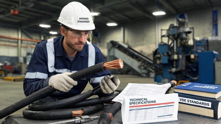
Mining equipment cable is selected for the electrical duty and the way the machine moves, pulls, bends, reels or exposes the cable. A suitable design must match the equipment route, voltage, conductor functions, environmental hazards and terminations—not just a familiar cable name or outside diameter.
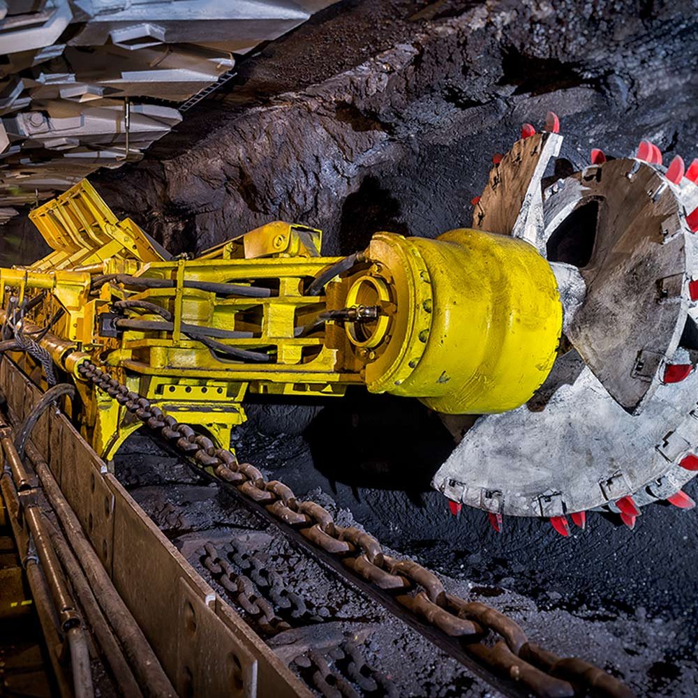
For an electrical engineer, maintenance planner or purchasing team, the practical question is not simply “Which mining cable is available?” It is “What will this cable experience on this machine?” A route that repeatedly drags across rock needs a different assessment from a cable that bends on a reel, feeds a pump in a wet area or supplies a relatively fixed distribution point.
TEBAOFLEX special cable solutions are specified from application data. Capturing that data early helps a project team compare suitable constructions and avoid a replacement that looks similar but does not match the installation duty.
Start with the equipment motion
Equipment motion is the first selection branch because it determines the mechanical stresses that act on the cable. A trailing cable behind an excavator, drill, mobile crusher or dumper can see surface contact, tension, flexing and occasional twisting. A reeling cable works through a controlled bend cycle around the selected drum and guide system. A fixed feeder has a different priority: route protection, support, bending during installation and long-term environment.
Do not call every flexible cable a trailing cable. Record whether the cable is dragged, reeled, festooned, suspended, stationary after installation or intermittently moved for maintenance. Then document where it touches terrain, rollers, guides, machine frames, water, oil, process material or vehicle paths. This simple route map is often more valuable than starting from a model name.
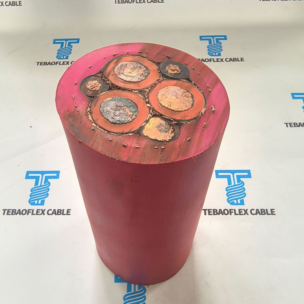
Map the cable route before choosing a construction
Walk the complete route from supply point to equipment connection. Mark transition points such as drum exits, guides, bends, clamps, junction boxes and entry points into equipment. These are where bending, rubbing, compression or tensile load can become concentrated. Also note the free length, the maximum travel, the lowest bend position and whether the route allows the cable to twist.
Environmental inputs belong on the same route drawing. Underground and surface sites may expose a cable to moisture, mud, abrasive fines, rock, sunlight, temperature changes and chemical contact. The right outer sheath and support arrangement are decided from verified conditions, not assumptions. If a route crosses haul traffic or moving plant, cable protection and operational controls must be considered with the site team.
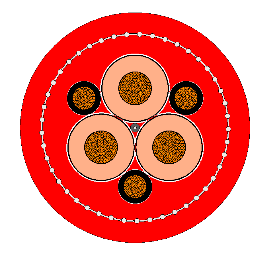
Match electrical functions to the equipment
Next, confirm what the circuit must carry: power, protective earth, a ground-check or pilot function where required, control, signal, data or fibre. The terminal schedule, protection settings and equipment documentation should be reviewed together; core count alone is not a complete functional specification.
For large mobile equipment, the SHD-GC Mining Cable product page is a relevant starting point for shielded portable-power and ground-check discussions. For heavily dragged open-pit routes, the (N)TSCGEWOEU-TR heavy-duty trailing cable illustrates a separate application direction. These examples are not interchangeable by name: the final mining equipment cable must match the approved electrical and mechanical specification.
Compliance should also be named precisely. For equipment installed in the United States, verify the applicable MSHA approval or acceptance requirements and cable marking with the project documentation. MSHA maintains information on flame-resistant cables accepted for mine use. Elsewhere, apply the local mining rules, contract requirements and relevant product standard rather than assuming a U.S. approval applies internationally.
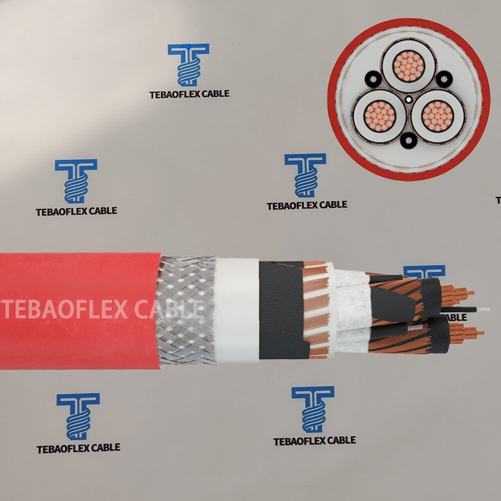
Mining equipment cable RFQ checklist
A useful quotation request gives the cable supplier enough detail to assess the application without guessing. The table below can be copied into a project enquiry.
| Information to provide | What to record | Why it matters |
|---|---|---|
| Equipment and task | Machine type, application and operating location | Connects the cable to the actual duty, not a generic industry label. |
| Motion type | Trailing, reeling, fixed, suspended or intermittent movement | Sets the mechanical selection path. |
| Route details | Travel, free length, bends, guides, drum data and contact points | Identifies likely bend, tension and abrasion locations. |
| Electrical duties | Voltage, load, phases, earth, pilot/ground-check, control and data functions | Confirms the required construction and terminations. |
| Environment | Water, mud, oil, UV, temperature, rock, dust and chemical exposure | Supports sheath and protection decisions. |
| Compliance evidence | Project standards, local approvals, cable marking and test documents | Avoids assuming that a similar product meets the project requirement. |
| Existing-cable evidence | Photos, identification marking, cut sample, failure history and termination images | Provides a reliable starting point for replacement assessment. |
Five replacement mistakes to avoid
- Copying a model name without confirming the route. A familiar designation does not confirm that movement, cable length or protection conditions are unchanged.
- Choosing from voltage alone. Voltage is essential, but it does not describe bending, tension, abrasion or torsion.
- Treating a photograph as the full specification. Images help identify a cable and document damage, but the marking, data sheet and terminal plan remain essential.
- Leaving out the terminations. Clamps, glands, strain relief and connector space can decide whether a cable is supported correctly in service.
- Assuming an approval transfers between projects. Confirm the required jurisdiction, mine rules and product documentation for the specific installation.
For single-conductor flexible power connections and related equipment work, see the DLO cable guide. It explains where that cable type fits, while this article focuses on motion-led selection for mining equipment routes.
Frequently asked questions
What is the difference between trailing and reeling cable?
A trailing cable is assessed for movement along the ground or alongside mobile equipment. A reeling cable is assessed around a powered drum, guide system and repeated bend cycle. Both may be flexible, but the route and mechanical demands are different.
How is the voltage rating selected?
Start from the electrical system and equipment documentation, then confirm conductor sizing, insulation system, protection coordination and applicable project requirements. Do not select voltage rating from the application name alone.
When is a ground-check function needed?
Ground-check or pilot functions are project and jurisdiction dependent. Identify the required protective scheme from the equipment and mine electrical specification before choosing the cable construction.
Can a mining cable be used in wet or submerged areas?
Only when the documented product construction and the installation conditions support that use. State the water exposure, depth where relevant, route and operating duration in the enquiry so suitability can be evaluated.
What should be included in a mining equipment cable quotation request?
Include the equipment type, motion, route sketch, electrical requirements, environment, required standards, cable marking and photos of the installed cable and terminations. You can send your mining equipment requirements for a project-specific review.
Turn site data into a defensible cable specification
The most reliable mining equipment cable selection starts with evidence from the machine and route. When motion, contact points, electrical functions, environment and compliance requirements are documented together, the cable proposal can be assessed for the real duty instead of a generic description. TEBAOFLEX can help review those inputs before a replacement or new-equipment order is finalised.
Last reviewed: August 2026. This article provides technical selection guidance; final suitability must be confirmed against the project specification, local rules and equipment requirements.