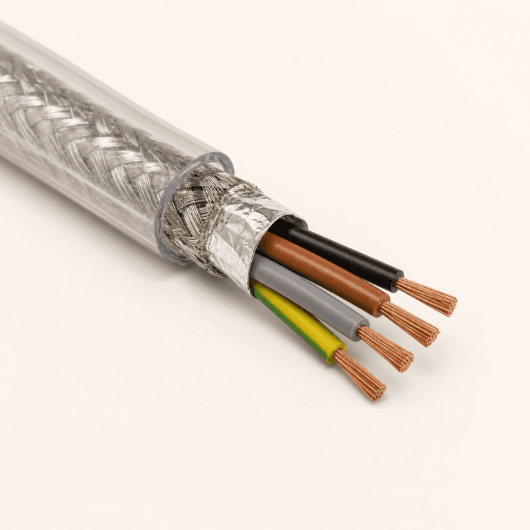
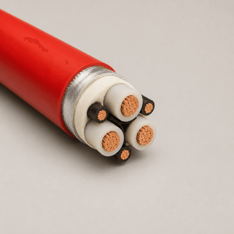
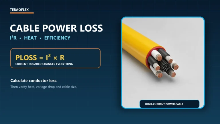
Converting amps to cable size is not a one-step calculation. Load current establishes the minimum current-carrying requirement, but the final conductor size also depends on insulation temperature, ambient temperature, installation method, cable grouping, conductor material, circuit length, voltage drop and the standard adopted for the project.
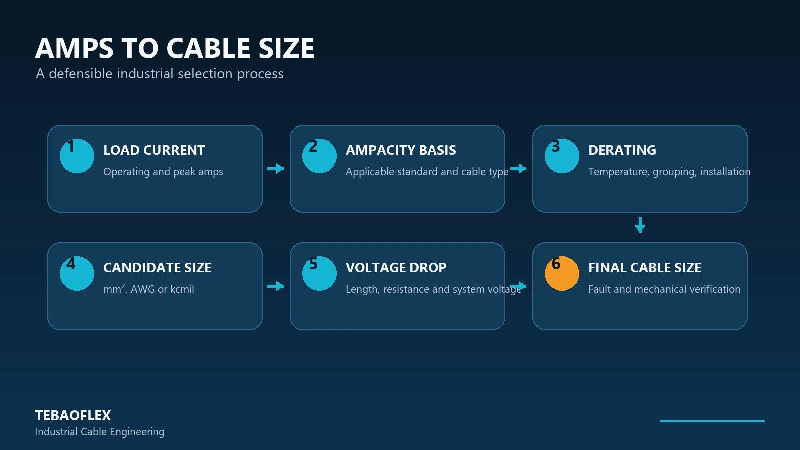
A cable that is suitable for 100 A in free air may not have the same allowable current when it is installed in conduit, grouped with other loaded cables or operated in a hot industrial area. The practical route is amps → design current → ampacity basis → derating → candidate mm²/AWG → voltage-drop check → final industrial cable. This guide explains that process without presenting a misleading universal amp-to-size chart.
| Selection step | Question to answer |
|---|---|
| 1. Current | How many continuous and peak amps must the circuit carry? |
| 2. Cable type | Is the cable fixed, portable, flexible, reeling or trailing? |
| 3. Temperature | What conductor, ambient and termination limits apply? |
| 4. Installation | Will it run in air, tray, conduit, ground or a grouped route? |
| 5. Derating | Which correction factors apply under the selected standard? |
| 6. Size | Which mm², AWG or kcmil size meets corrected ampacity? |
| 7. Length | Does voltage drop require a larger conductor? |
| 8. Fault | Does the cable meet short-circuit withstand requirements? |
| 9. Mechanical | Do OD, bending radius, weight and movement duty suit the equipment? |
Can You Convert Amps Directly to Cable Size?
No single conversion is valid for every cable and installation. Amps are the starting input, not the finished answer. A current value must first be matched to an ampacity table or verified manufacturer data that actually applies to the cable construction, conductor material, insulation system and installation method.
The initial size is then corrected for temperature and grouping, checked for voltage drop and fault duty, and reviewed against the mechanical requirements of the machine. This is why a responsible amps-to-cable-size result is a documented selection, not a number copied from an unlabeled chart.
What Determines Cable Size for a Given Current?
Load current and duty cycle
Higher current normally requires more conductor area, but the input must be correct. Use verified operating current, including the duty cycle and any relevant peak or starting condition. For motors, begin with the nameplate full-load current and the protection and sizing rules applicable to that project—not a kW-to-amps estimate used in isolation.
Conductor material
Copper and aluminum have different conductivity, resistance, density and termination requirements. Copper’s high conductivity can allow a smaller conductor to achieve comparable electrical performance, while aluminum may reduce weight. Neither material should be sized by a fixed area ratio; use the applicable ampacity and installation data for the actual construction. The Copper Development Association provides background on copper electrical conductivity and the effects of temperature and alloying.
Insulation and termination temperature
PVC, XLPE, EPR and rubber insulation systems can have different operating limits and may be covered by different ampacity data. A 90°C insulation marking does not automatically permit the complete circuit to be sized from a 90°C column: equipment terminals, connectors, installation rules and the cable’s own listing can impose a lower limit.
Ambient temperature
A cable in a 50°C machinery area cannot reject heat as easily as the same cable under the reference ambient condition of a table. The applicable temperature correction factor may therefore reduce allowable ampacity. Confirm both normal ambient temperature and local heat sources along the route.
Installation method and grouping
Free air, tray, conduit, buried routes and groups of loaded cables dissipate heat differently. The number of current-carrying conductors also matters. Our cable ampacity calculation guide explains these thermal effects and how correction factors are applied.
Cable length and voltage drop
Ampacity can pass while voltage drop fails. At the same current, a longer route has more conductor resistance and normally produces more voltage drop. Long runs, low-voltage DC circuits, high-current loads and motors deserve particular attention. Use the complete formulas in our cable voltage drop calculation guide and the design logic in cable length and voltage drop.
Step by Step: How to Convert Amps to Cable Size
Step 1 — Determine the design current
Record continuous operating current, relevant peak current, duty cycle and load type. If only power is known, determine current for the actual electrical system. In simplified form, DC uses I = P/V; single-phase AC uses I = P/(V × PF × η); and balanced three-phase AC uses I = P/(√3 × V × PF × η). Use measured, nameplate or approved design data whenever available.
Step 2 — Identify the electrical system and cable duty
Confirm DC, single-phase AC or three-phase AC; system voltage; number of loaded conductors; grounding arrangement; and whether the cable is fixed or moving. A flexible trailing cable, a single-conductor DLO cable and a fixed building wire may all use familiar size names, but they are not interchangeable products.
Step 3 — Select the applicable ampacity basis
Choose one defensible basis: the project’s IEC or national installation rules, NEC requirements where adopted, verified manufacturer data, and the applicable cable product standard. Do not merge an IEC mm² table and a North American AWG table into a universal chart. IEC 60364-5-52:2009+AMD1:2024 covers selection and erection of low-voltage wiring systems and includes cable-sizing and voltage-drop considerations.
Step 4 — Apply derating factors
Where the selected method uses multiplicative factors, the basic relationship is:
Required base ampacity ≥ design current ÷ combined derating factor
For an instructional example, take a 120 A design current, a temperature factor of 0.91 and a grouping factor of 0.80. The combined factor is 0.91 × 0.80 = 0.728, so the required base-table ampacity is 120 ÷ 0.728 ≈ 165 A. These factors are illustrative only; they must come from the method adopted for the real installation. The example does not mean that 120 A always requires one fixed conductor size.
Step 5 — Select an initial mm², AWG or kcmil size
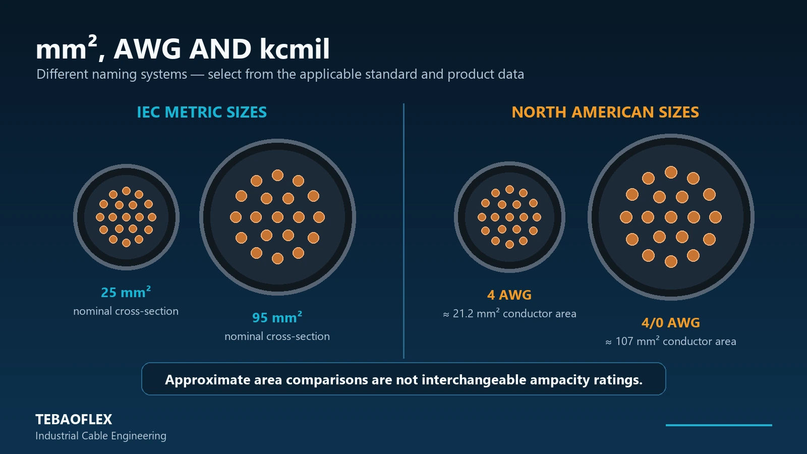
Now select the smallest listed conductor that meets the corrected ampacity requirement. IEC-oriented projects commonly use nominal mm² sizes, while North American products use AWG and kcmil. They are different sizing systems, and a nearby area match is not an exact electrical or approval equivalence. See cable size and cross-section selection for a deeper workflow.
Step 6 — Check voltage drop
Calculate voltage drop with the actual one-way route length, circuit arrangement and cable resistance or impedance at the relevant temperature. If the result exceeds the equipment or project limit, increase conductor size and calculate again. For low-voltage battery and charging systems, the DC cable voltage drop and sizing guide addresses the sensitivity of 12 V, 24 V, 48 V and other DC systems.
Step 7 — Verify protection and short-circuit withstand
Ampacity covers normal operation; short-circuit withstand covers a fault. Check protective-device coordination, fault magnitude, clearing time, conductor temperature limit and the rules of the selected standard. Upsizing for voltage drop does not remove the need for this separate verification.
Step 8 — Check mechanical and installation requirements
For reeling, trailing, festoon, drag-chain and mining applications, a larger conductor changes overall diameter, weight, bend radius, reel capacity, tensile load and dynamic force. Confirm the cable still fits the machine and installation hardware. The mobile equipment cable selection checklist covers these non-electrical constraints.
Amps to mm² Cable Size: Why There Is No Universal Chart
| Input | Why it can change cable size |
|---|---|
| Amps | Defines the current-carrying requirement |
| Cable construction | Changes thermal and mechanical performance |
| Insulation system | Affects permissible conductor temperature |
| Ambient temperature | May require correction or derating |
| Installation method | Changes heat dissipation |
| Grouping | Multiple loaded cables can reduce allowable current |
| Cable length | May force a larger size for voltage drop |
| Material | Copper and aluminum differ electrically and mechanically |
| Standard | IEC, NEC and project rules use different conditions and requirements |
An amps-to-mm² chart is only valid when its construction and installation assumptions are stated. Without those assumptions, the chart cannot tell an engineer whether its number applies to a single conductor in air, a multicore cable, a grouped route, a flexible cord or a moving industrial cable.
Amps to AWG Cable Size
In the AWG system, a lower gauge number represents a larger conductor; sizes beyond 4/0 are commonly stated in kcmil. The correct sequence remains AWG → applicable ampacity data → correction factors → voltage drop → final size. Our AWG current rating and mm² conversion guide provides area references and clearly states the assumptions behind approximate ratings.
Cable Size for 50 A, 100 A, 200 A and 300 A
| Load current | What must be checked before selecting size |
|---|---|
| 50 A | Ampacity basis, conductor material, temperature, installation and route length |
| 100 A | Derating and voltage drop, especially on grouped or long runs |
| 200 A | Larger mm²/AWG/kcmil options, terminals, route space and handling |
| 300 A+ | Large single conductors or an engineered parallel arrangement, plus current sharing and protection |
For 50 A: select from the applicable ampacity basis, apply all correction factors, then check voltage drop. For 100 A: do the same, with closer attention to long-route voltage drop. For 200 A: terminal capacity, cable OD and installation handling become increasingly important. For 300 A or more: large single conductors or parallel conductors may be considered, but parallel paths require an engineered design with compatible cable type, size, length, routing and terminations so current can share correctly.
Worked Example: Selecting Cable Size for a 120 A Industrial Load
Assume a three-phase industrial machine has a confirmed 120 A design current, a 35 m one-way cable route and a copper flexible power cable requirement.
- Confirm the input: 120 A is the approved design current, not an estimate that ignores power factor, efficiency or duty.
- Choose the governing data: identify the project standard, cable construction and installation method before opening an ampacity table.
- Apply correction factors: if the verified combined factor is 0.80, required base ampacity is 120/0.80 = 150 A.
- Select a candidate: choose an available conductor whose base ampacity meets or exceeds 150 A under that table’s reference conditions.
- Check voltage drop: use 35 m, the actual system voltage and the candidate cable’s resistance/impedance data.
- Check the application: verify fault duty, terminals, OD, bending radius, weight, route and movement requirements.
The example deliberately stops before naming one mm² or AWG size. Without a defined cable construction, table, temperature basis and installation condition, assigning a size would create false precision.
Why the Same 100 A Can Require a Different Cable Size
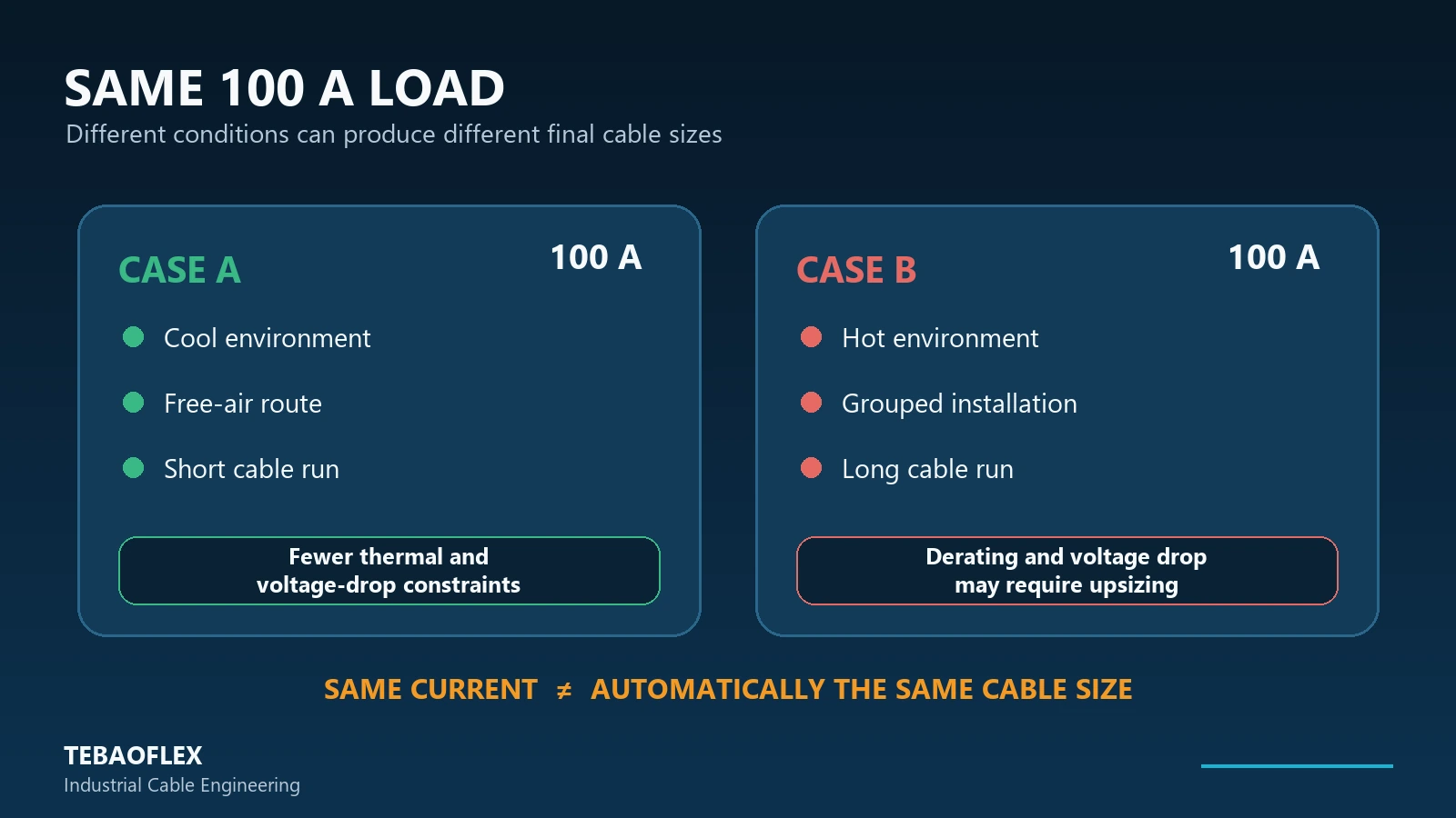
Consider two circuits with the same 100 A operating current. Cable A has a short route, a cool environment and good heat dissipation in free air. Cable B has a long route, a hotter environment and grouping with other loaded cables. Cable B may need more conductor area because its corrected ampacity is lower, its voltage drop is higher, or both.
Does Cable Length Change the Size Required for the Same Amps?
Yes, it can. Ampacity protects the thermal limit in normal service. Distance adds resistance, voltage drop and I²R loss. A conductor can therefore pass the current-rating check but still be too small for a long route. Use verified conductor data; our cable resistance formula guide explains how length, area, material and temperature affect resistance.
Flexible Cable Ampacity vs Fixed-Installation Cable
An online building-wire chart is not automatically a product-selection chart for mining trailing cable, DLO, reeling cable or festoon cable. Construction, number of cores, insulation, jacket, movement duty, route and approval basis may differ. NFPA material for the NEC separately points users to the flexible-cord and flexible-cable ampacity provisions rather than treating every conductor table as interchangeable; see the NFPA committee material on conductor ampacity.
For example, the TEBAOFLEX DLO flexible single-conductor power cable uses flexible stranded tinned copper, EPR insulation and an XL-CPE jacket, with published sizes from 14 AWG to 1111.1 kcmil. The page explicitly requires final ampacity to be confirmed for the actual installation. Conductor size alone does not establish application suitability; voltage rating, marking, routing and termination still need verification.
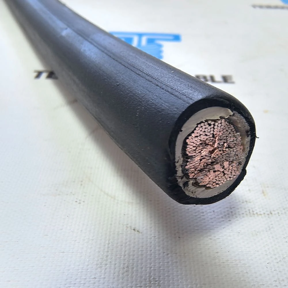
For moving industrial equipment using metric sizes, BUFLEX-M flexible industrial power cable is published in phase-conductor sizes from 25 to 240 mm². Across that range, its listed overall diameter, weight and dynamic bending radius rise substantially—evidence that electrical upsizing also changes the mechanical cable. The Type W and DLO specification guide further explains why a multi-conductor heavy-duty cable and a single-conductor DLO cable cannot be selected from AWG alone.
Final Industrial Cable-Size Checklist
- Confirmed operating, continuous and peak current
- System voltage, phases, power factor and efficiency where relevant
- Copper or aluminum conductor and required flexibility class
- Applicable standard, product approval and ampacity basis
- Insulation, ambient and termination temperature limits
- Installation method, grouping and number of loaded conductors
- One-way routed length and voltage-drop limit
- Short-circuit withstand and protective-device coordination
- Overall diameter, bend radius, weight and movement duty
- Terminations, gland range, reel or tray capacity and available route space
If several of these inputs are unknown, treat any wire-size answer as preliminary. For a broader product-level workflow, use the industrial cable selection guide.
Frequently Asked Questions
How do I convert amps to cable size?
Amps are the starting point, not a complete cable-size conversion. Determine design current, use an applicable ampacity table or verified product data, apply derating, select a candidate mm²/AWG size, and then check voltage drop, fault duty and mechanical suitability.
What cable size do I need for 50 amps?
There is no universal size for 50 A. The answer depends on conductor material, cable construction, insulation temperature, ambient temperature, installation, grouping, length and the governing standard.
What cable size do I need for 100 amps?
Select the initial size from the applicable 100 A ampacity basis after correction factors. Then check voltage drop; a long 100 A route may require a larger conductor than the minimum thermal selection.
What cable size do I need for 200 amps?
Use the same documented process, then pay particular attention to large-conductor terminals, cable OD, bend radius, route space and installation handling. A fixed 200 A-to-mm² answer is unsafe without those conditions.
How many amps can a 25 mm² cable carry?
There is no single current rating for every 25 mm² cable. A 25 mm² conductor can appear in different cable constructions and installation methods with different allowable ampacities. Use the relevant table or verified product data and apply the required factors.
Is cable size based only on current?
No. Length, voltage drop, temperature, installation, grouping, short-circuit duty, terminations and mechanical requirements can all change the final cable size.
Does cable length affect the cable size needed for the same amps?
Yes. A longer route increases conductor resistance and voltage drop. The cable may pass ampacity yet still need upsizing to deliver acceptable voltage at the equipment.
Is AWG the same as mm²?
No. AWG is a gauge system; mm² is nominal conductor cross-sectional area. Approximate area comparisons are useful for orientation, but they do not make two cables identical in ampacity, construction or approval.
Can I use an online wire-size chart for a flexible industrial cable?
Only after confirming that the chart’s standard, conductor material, cable construction, temperature basis and installation assumptions apply. A building-wire chart should not be assumed suitable for DLO, reeling, festoon or mining cable.
Need Help Converting Load Current to the Right Cable Size?
Send TEBAOFLEX your system voltage, continuous and peak current, cable length, conductor preference, installation method, ambient temperature, movement type and applicable standard. Our team can review ampacity, derating, voltage drop and mechanical requirements before confirming a suitable cable configuration.
Technical review basis: IEC 60364-5-52:2009+AMD1:2024, official NFPA committee material, verified TEBAOFLEX product data and the linked calculation guides. Updated September 24, 2026. Final selection must follow the edition, national implementation, product marking and engineering requirements applicable to the project.