Ohm’s Law for electrical cables explains how voltage, current and conductor resistance interact in a real power circuit. For engineers and procurement teams, the relationship is useful because every copper or aluminum conductor has measurable resistance. That resistance contributes to voltage drop and power loss, and it changes with conductor material, cross-sectional area, circuit length and operating temperature.
Ohm’s Law is an essential starting point, but it is not a complete cable-selection method. A suitable industrial cable must also satisfy ampacity, temperature, installation, mechanical-duty and applicable-standard requirements. This guide connects the basic formula to practical cable decisions without replacing a project-specific engineering calculation.
What Is Ohm’s Law?
Ohm’s Law describes the relationship between voltage, current and resistance in an electrical circuit:
V = I × R
| Symbol | Meaning | Unit |
|---|---|---|
| V | Voltage or potential difference | Volt (V) |
| I | Electrical current | Ampere (A) |
| R | Electrical resistance | Ohm (Ω) |
The same relationship can be rearranged for the quantity that must be found:
- V = I × R to calculate voltage across a resistance.
- I = V ÷ R to calculate current when voltage and resistance are known.
- R = V ÷ I to calculate resistance from measured voltage and current.
This linear relationship is a useful model for an approximately ohmic conductor under defined conditions. OpenStax provides a broader introduction to current, resistance and Ohm’s Law. In cable engineering, the next question is how the conductor itself contributes resistance to the circuit.
How Does Ohm’s Law Apply to Electrical Cables?
An electrical cable is not a perfect conductor. As current passes through its metallic conductor, the conductor’s resistance produces a voltage difference along the cable and dissipates energy as heat. The basic relationship is straightforward:
- A longer conductor has more resistance and normally creates more voltage drop.
- A larger conductor cross-section has less resistance and normally creates less voltage drop.
- A higher current creates a larger voltage drop across the same conductor resistance.
- A higher conductor temperature normally increases the resistance of copper and aluminum conductors.
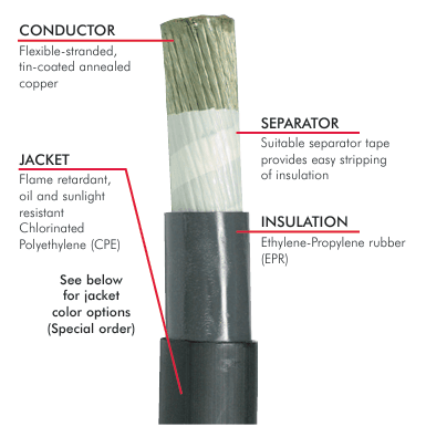
For a simple DC circuit, the voltage drop across the complete cable path can be estimated with Vdrop = I × Rcircuit. The resistance value must represent the full current path. In a two-conductor DC circuit, that normally includes both the outgoing conductor and the return conductor.
What Determines Cable Resistance?
Conductor material
Copper and aluminum have different electrical resistivity, density and mechanical characteristics. Copper is widely used in flexible industrial cables because it combines relatively low electrical resistance with useful ductility. Material alone does not determine cable suitability; conductor construction, plating, insulation and the complete cable design must match the application.
Conductor cross-section
For the same material, length and temperature, increasing the conductor cross-sectional area reduces resistance. A 1.5 mm² conductor therefore has more resistance than a much larger conductor of the same material and length. This is one reason conductor size affects voltage drop, although the final size must also be checked against current-carrying capacity and installation conditions.
For a structured selection process, see the cable size and cross-section selection guide. It explains how load current, cable length, voltage drop, installation and mechanical duty work together.
Cable length
Resistance increases with conductor length. If every other variable remains unchanged, doubling the conductor length doubles its resistance. This makes circuit length especially important for long mobile-equipment feeds, battery systems, airport ground-power connections and remote industrial loads.
Always distinguish between the physical one-way route and the electrical circuit length. In many DC and single-phase calculations, both the outgoing and return paths contribute to total resistance. Using only the one-way length can understate the estimated voltage drop.
Conductor temperature
Conductor resistance is specified at a reference temperature and changes as operating temperature changes. A cable operating warm will not have exactly the same resistance as the same cable measured cold. Accurate project calculations should use the applicable conductor data, temperature correction and engineering method rather than a generic room-temperature value.
Cable Resistance Formula
The relationship between conductor material, length and area is commonly expressed as:
R = ρ × L ÷ A
- R is conductor resistance.
- ρ is the material resistivity at the stated temperature.
- L is conductor length.
- A is conductor cross-sectional area.
The equation explains why a longer cable has more resistance and a larger conductor has less resistance. However, reliable calculations require consistent units and appropriate input data. Published conductor resistance in Ω/km is often more practical than calculating from nominal resistivity because a real stranded conductor may differ from an ideal solid conductor.
The RMIT University Learning Lab also shows how conductor dimensions and length connect to resistance before Ohm’s Law is applied to a circuit in its Ohm’s Law learning resource.
Example: Ohm’s Law in an Industrial DC Cable Circuit
Consider a simplified 48 V DC industrial circuit with a 20 A load. Assume the total measured or calculated resistance of the outgoing and return conductors is 0.10 Ω.
- Calculate voltage drop: Vdrop = I × R = 20 A × 0.10 Ω = 2 V.
- Calculate load voltage: 48 V − 2 V = 46 V.
- Calculate percentage voltage drop: 2 V ÷ 48 V × 100 = 4.17%.
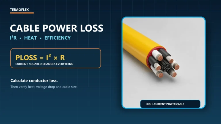
- Calculate conductor power loss: Ploss = I² × R = 20² × 0.10 = 40 W.
This example is illustrative, not a design recommendation. It shows an important distinction: a cable may have sufficient ampacity for 20 A but still produce an unacceptable voltage drop for the connected equipment. The acceptable limit depends on the equipment, system, project specification and applicable installation requirements.
How Cable Size Affects Resistance and Voltage Drop
| Change | Effect on resistance | Effect on voltage drop at the same current |
|---|---|---|
| Longer conductor | Increases | Increases |
| Larger conductor cross-section | Decreases | Decreases |
| Higher current | No direct change in basic conductor resistance | Increases |
| Higher conductor temperature | Normally increases | Normally increases |
A larger conductor can reduce resistance and voltage drop, but simply choosing the largest available size is not a complete engineering solution. Larger cables add cost, weight, minimum-bending-radius considerations and termination requirements. The cable must fit the equipment, connectors, route and movement duty.
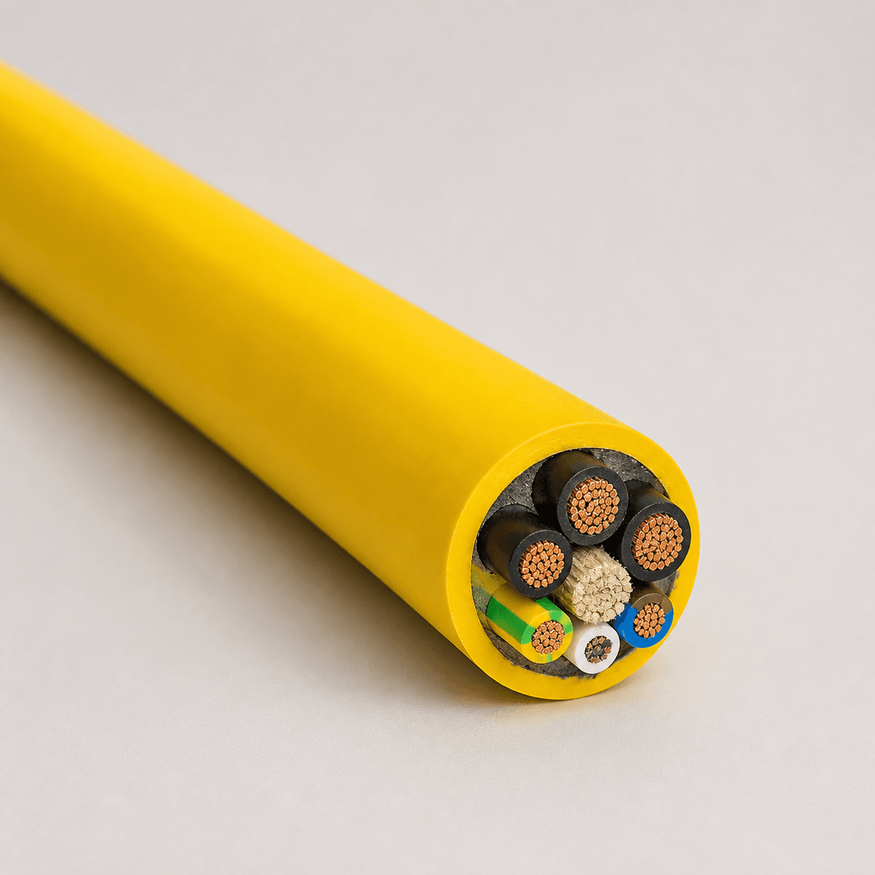
The TEBAOFLEX flexible industrial power cable range illustrates how cable construction must combine conductor selection with insulation, sheath and mechanical requirements. Product suitability and available dimensions should be confirmed against the current datasheet and project specification.
Ohm’s Law and Cable Ampacity Are Not the Same Thing
Ohm’s Law relates voltage, current and resistance. Ampacity is the maximum current a cable can carry continuously under defined conditions without exceeding the permitted conductor or insulation temperature. They address connected but different questions.
An ampacity assessment may need to consider:
- conductor material, size and construction;
- insulation temperature rating;
- ambient or surrounding temperature;
- installation in air, conduit, tray, soil or water;
- cable grouping and heat dissipation;
- duty cycle and applicable standards.
Ohm’s Law cannot replace an ampacity calculation. A practical cable selection checks both thermal current capacity and voltage drop. The cable ampacity calculation guide explains current rating and derating factors in more detail.
AWG, mm² and Electrical Resistance
American Wire Gauge and metric cross-sectional area describe conductor size in different ways. In the AWG system, a smaller gauge number represents a larger conductor. For example, 6 AWG is larger than 12 AWG. A larger conductor generally has lower resistance when material, length and temperature are the same.
AWG-to-mm² values are approximate comparisons rather than interchangeable designations. Conductor stranding, construction standards and permitted tolerances matter. Use the AWG current rating and mm² conversion guide to compare common sizes, then verify the applicable product data and installation rules.
Does Ohm’s Law Apply to AC and VFD Cables?
Ohm’s Law remains a foundation for AC circuits, but a simple DC resistance value may not be enough. AC voltage-drop calculations can require impedance rather than resistance alone. Depending on the system, this may include reactance, power factor, frequency and conductor arrangement.
Variable-frequency-drive systems add further considerations. Fast switching edges, common-mode voltage, cable capacitance, EMC performance, shielding and grounding can influence motor-cable behavior. Medium-voltage and long AC circuits also require methods appropriate to the system and applicable standards.
For these applications, cable selection should not rely on DC resistance alone. TEBAOFLEX supplies industrial and control cables, including flexible power, control, servo and VFD constructions. The correct cable depends on converter output, motor data, cable route, length, EMC requirements and approval scope.

A Practical Cable-Selection Sequence
Use Ohm’s Law as one step in a wider selection process:
- Confirm system voltage, phase and frequency.
- Determine continuous, starting and peak current.
- Confirm one-way route length and complete circuit length.
- Check ampacity for the actual installation and ambient conditions.
- Calculate voltage drop using the correct resistance or impedance data.
- Verify short-circuit, protection and termination requirements.
- Confirm fixed, flexible, reeling, festoon or drag-chain duty.
- Check temperature, oil, water, chemicals, abrasion and other environmental exposure.
- Verify the applicable product standard, certification and project documentation.
This sequence prevents a common error: selecting a conductor only from a current table while overlooking route length and voltage at the load. It also prevents the opposite error—selecting only for low resistance while overlooking thermal, mechanical or compliance limits.
Information to Include in a Cable RFQ
To obtain a useful recommendation and quotation, provide:
- nominal and maximum system voltage;
- DC, single-phase AC or three-phase AC;
- load current, starting current and duty cycle;
- one-way cable length;
- preferred conductor size or allowable voltage drop, if specified;
- installation method and ambient temperature;
- fixed or moving application, with bend and travel details;
- oil, water, UV, chemical, abrasion or flame requirements;
- required cable standard, approval and documentation;
- core count, shielding, grounding and control-core requirements.
Frequently Asked Questions
What is Ohm’s Law in electrical cables?
Ohm’s Law relates voltage, current and resistance through V = I × R. In an electrical cable, conductor resistance creates voltage drop when current flows. The formula helps estimate this effect, but cable sizing must also consider ampacity, temperature, installation, mechanical duty and applicable standards.
How do you calculate cable resistance?
A basic material relationship is R = ρL/A, where resistivity, length and cross-sectional area determine resistance. For practical engineering, manufacturers’ maximum conductor-resistance values or verified Ω/km data are often preferable. Use consistent units, the full current-path length and the relevant conductor temperature.
Does a longer cable have more resistance?
Yes. For the same material, cross-section and temperature, resistance increases in proportion to conductor length. Remember that the complete electrical path may be longer than the one-way installation route, particularly in DC and single-phase circuits.
Does a larger cable reduce voltage drop?
A larger conductor normally has lower resistance, so it reduces voltage drop at the same current and length. Final sizing must still account for terminals, bend radius, weight, installation, protection, ampacity and applicable project rules.
How does cable size affect current and resistance?
Increasing conductor cross-section lowers resistance and can improve current-carrying capability, but ampacity does not come from Ohm’s Law alone. Insulation temperature, installation method, grouping and ambient conditions influence the permitted current rating.
Can Ohm’s Law be used for AC cables?
It is a foundation, but AC systems may require impedance, reactance and power factor. VFD, long-circuit and medium-voltage applications can also require frequency-dependent, transient and EMC analysis. Use a calculation method appropriate to the actual system.
Need Help Selecting the Right Cable Size?
Send TEBAOFLEX your operating voltage, load current, cable length, installation method, movement requirements and working environment. Our team can review the application and help identify a suitable industrial cable configuration. Final selection remains subject to confirmed product data, project requirements and applicable standards.
Technical note: The calculations in this article are simplified educational examples. They are not a substitute for project-specific engineering, manufacturer data or applicable electrical codes and standards.