Three-phase motor cable sizing should start with verified motor data—not with a universal kW-to-mm² chart. Motor output, rated voltage, full-load current, power factor, efficiency, starting method, route length, installation conditions and drive type can all change the final conductor size and cable construction.
When nameplate current is available, it is normally a better engineering input than a generic kW-to-amps estimate. The selected conductor must then pass ampacity, derating, running and starting voltage-drop, short-circuit and protection checks. Finally, the cable construction must suit the real application: a fixed 400 V pump, a 480 V conveyor motor, a crane drive and a moving VFD circuit do not impose the same requirements.
| Motor cable sizing input | Why it matters |
|---|---|
| Rated motor current | Main electrical sizing input when verified |
| Voltage | Changes current for the same motor power |
| Motor kW or hp | Useful for preliminary current estimation |
| Power factor | Required for AC power-to-current conversion |
| Efficiency | Required when converting motor output power |
| Starting method | Defines the starting-current and system check |
| Cable length | Affects running and starting voltage drop |
| Installation | Changes heat dissipation and allowable ampacity |
| VFD | Adds drive, EMC, screening and length requirements |
| Movement | Determines fixed versus flexible construction |
What Determines Three-Phase Motor Cable Size?
Motor full-load current
The verified rated current or full-load current is the best starting input once the motor has been selected. Two motors with the same nominal kW can have different current because their efficiency, power factor, design and rated voltage differ. A “30 kW motor = 16 mm² cable” shortcut hides those variables and also says nothing about installation or length.
Motor power: kW or hp
If the motor has not yet been selected, output power can support a preliminary current estimate. For a balanced three-phase motor whose P value is mechanical shaft output:
I = P / (√3 × V × PF × η)
P must be converted to watts; V is line-to-line voltage; PF is power factor; and η is efficiency. If P already means real electrical input power, do not apply efficiency again. The separate kW to amps guide explains this distinction in detail.
System voltage
The same output power normally requires less current at higher voltage when the other assumptions remain equal. A 30 kW motor at 400 V, 415 V and 480 V therefore does not produce one universal current value. Confirm both the supply and the voltage shown for the motor connection.
Motor starting method
Direct-on-line (DOL), star-delta, soft-starter and VFD systems create different starting and cable-system questions. Do not assume one fixed multiple of full-load current. Use motor, starter or drive manufacturer data, together with the available bus voltage and driven-load requirements.
Cable length
A long motor feeder can pass the continuous ampacity check but fail a voltage-drop or starting-performance check. As one-way route length increases, cable impedance increases, which can push the design toward a larger conductor even when the running current is unchanged.
Installation and temperature
A cable in free air does not dissipate heat like the same cable in conduit, a grouped tray, insulation or a hot machinery area. Ambient temperature, number of loaded conductors, grouping and termination limits must match the ampacity method used.
Fixed motor versus moving motor
A stationary pump and a crane trolley motor may have identical electrical current but need very different cables. Moving equipment adds repeated bending, cable weight, tension, abrasion, torsion, travel speed and cable-management constraints. Conductor area is only one part of the specification.
How to Calculate Three-Phase Motor Current
For a preliminary estimate from mechanical motor output power:
I = Pout / (√3 × VLL × PF × η)
| Symbol | Meaning |
|---|---|
| I | Estimated motor line current, A |
| Pout | Mechanical motor output power, W |
| VLL | Line-to-line voltage, V |
| PF | Power factor at the relevant operating point |
| η | Motor efficiency expressed as a decimal |
| √3 | Balanced three-phase relationship, approximately 1.732 |
Calculated current is useful during preliminary design. Once the actual motor is selected, review manufacturer and nameplate current before final cable selection. The U.S. Department of Energy’s motor selection and application guide treats current, voltage, power factor, efficiency and output as distinct motor quantities rather than interchangeable values.
400 V vs 415 V vs 480 V Motor Current
Consider a 30 kW motor. For an instructional comparison, assume the rating is mechanical output, PF is 0.86 and efficiency is 0.93. Applying the same assumptions at each voltage gives:
| Three-phase supply | Approximate calculated current* |
|---|---|
| 400 V | 54.1 A |
| 415 V | 52.2 A |
| 480 V | 45.1 A |
*Illustrative calculated values only. Actual nameplate current depends on the motor design and should be used for final selection.
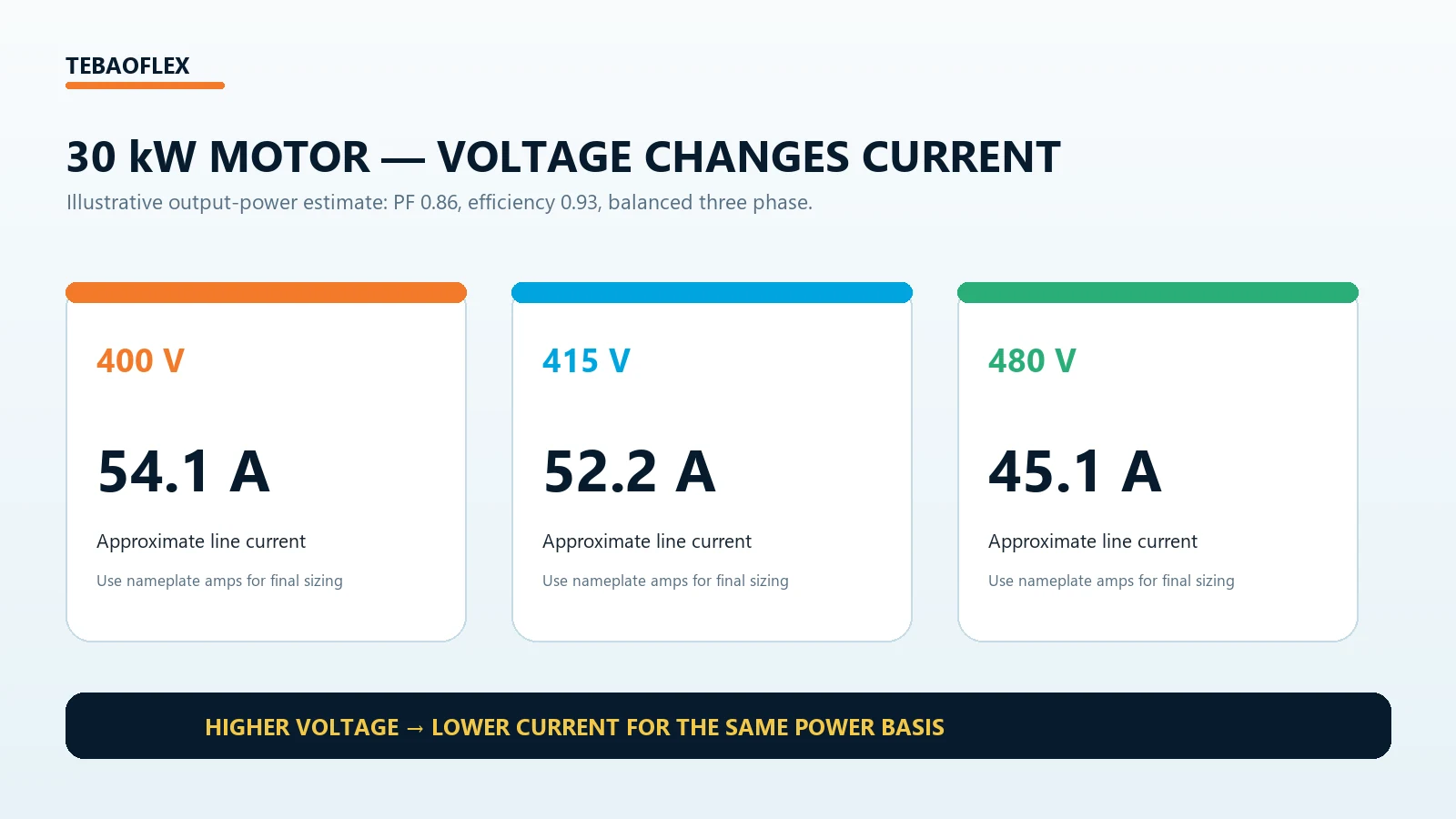
The comparison explains why a cable selected from motor kW alone can be wrong. Voltage changes current, while cable construction, installation, ambient temperature and route length determine how that current translates into conductor size.
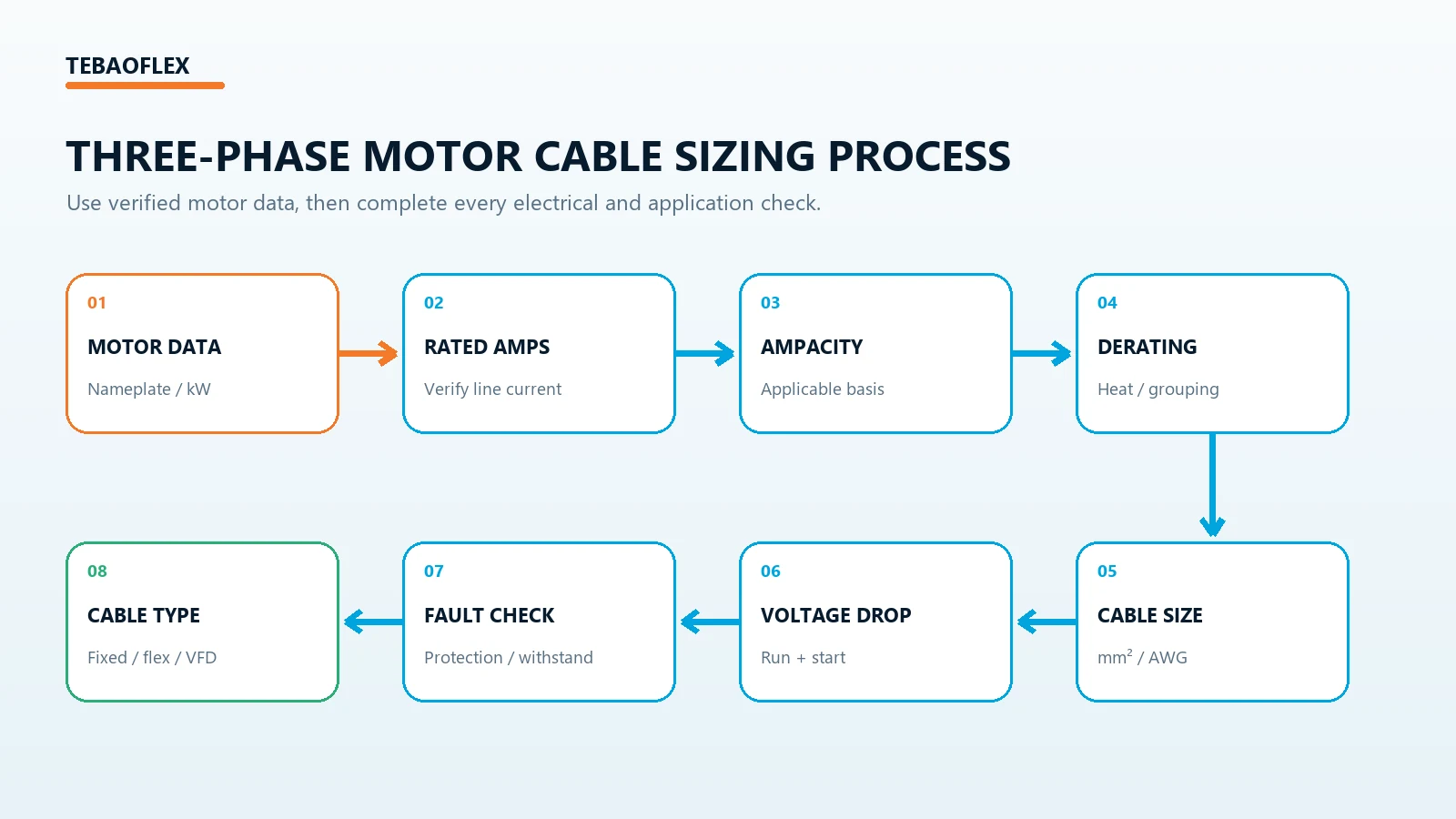
Step-by-Step Three-Phase Motor Cable Sizing
Step 1 — Record the motor nameplate data
Record rated kW or hp, voltage, current, phase, frequency, power factor, efficiency, duty and connection information. Also record the starting method or the exact VFD and motor combination. NEMA motor material identifies items such as rated power, voltage, amperes, phase and frequency as core motor data. For inverter-fed motors, NEMA MG 1 Part 31 likewise lists base-rating voltage, current, speed and frequency among required nameplate data.
Step 2 — Determine the design current
If verified nameplate current is available, begin with that value. If only output power is known, calculate a preliminary current using the applicable voltage, power factor and efficiency. Then apply the motor-circuit design method required by the adopted IEC, NEC, national code or project specification. A calculated value does not override mandatory motor-circuit rules.
Step 3 — Select the applicable ampacity basis
Choose ampacity data that applies to the actual conductor material, cable construction, insulation system, number of loaded conductors and installation method. Do not combine an IEC mm² table, a building-wire chart and flexible-cable data into one universal answer. The amps to cable size guide explains how to select a defensible basis.
Step 4 — Apply temperature and grouping derating
Correct the base ampacity for the actual conditions. A high ambient temperature, several loaded circuits touching in a tray, thermal insulation or a confined route can reduce allowable current. Use factors from the same method as the base ampacity; the cable ampacity calculation guide covers this stage without turning unrelated correction factors into one generic table.
Step 5 — Select a candidate mm² or AWG size
Select the smallest listed conductor that satisfies corrected ampacity, then treat it as a candidate—not the final selection. IEC-oriented projects usually use nominal mm² sizes; North American equipment may use AWG or kcmil. Approximate area conversion does not make two cable constructions electrically or mechanically equivalent. See cable size and cross-section selection for the wider conductor-size workflow.
Step 6 — Check running voltage drop
For a balanced three-phase circuit, a common engineering form is:
ΔV = √3 × I × L × (R cosφ + X sinφ)
Keep the units for L, R and X consistent, and use cable impedance at the relevant operating temperature. If the result is outside the equipment or project requirement, increase conductor size and calculate again. The three-phase cable voltage drop calculation guide explains the complete R/X/PF method.
Step 7 — Check motor starting conditions
Review starting current, starting duration, starter or drive method, available bus voltage and required motor-terminal voltage during acceleration. A conductor that passes continuous ampacity can still allow an unacceptable starting voltage dip on a weak supply or long feeder. Use the motor, starter or drive data and the project’s performance requirements rather than a universal starting-voltage limit.
Step 8 — Check short-circuit and protection requirements
Ampacity addresses normal thermal loading; short-circuit withstand addresses a fault. Verify prospective fault current, clearing time, protective-device coordination, conductor temperature limit and termination ratings. Upsizing for voltage drop does not eliminate this separate check.
Step 9 — Select the cable construction
Only after the electrical size is established should the product family be confirmed: fixed power cable, flexible motor cable, screened VFD cable, trailing cable or energy-chain cable. Check voltage rating, cores, grounding arrangement, screen design, outer diameter, bend radius, weight, environment and the cable’s documented motion duty.
Three-Phase Motor Cable Size Chart: How to Use One Safely
A motor cable size chart is useful only when its electrical and installation assumptions are stated. Before using a chart, verify every item below:
| Motor or cable information | What the chart must state |
|---|---|
| Motor power | kW or hp, plus whether it is input or output |
| Voltage | For example 400, 415 or 480 V |
| Current basis | Verified nameplate current or calculated current |
| Conductor material | Copper or aluminum |
| Insulation | PVC, XLPE, EPR or the applicable construction |
| Installation | Free air, tray, conduit, ground or another method |
| Ambient | Reference and actual temperature |
| Length | Voltage-drop assumption and one-way route |
| Standard | IEC, NEC, national rule or project specification |
A chart that maps 15 kW directly to one mm² value without these conditions is a screening shortcut, not a final cable design.
Worked Example: 30 kW, 400 V Three-Phase Motor
Assume 30 kW is mechanical output, supply is 400 V, PF is 0.86 and efficiency is 0.93. Preliminary current is 30,000 / (1.732 × 400 × 0.86 × 0.93) = 54.1 A.
The calculation does not justify an immediate mm² answer. A responsible continuation is:
- Compare 54.1 A with the selected motor’s verified nameplate current.
- Apply the project’s motor-circuit design-current rules.
- Choose ampacity data for the actual cable and installation.
- Apply ambient, grouping and installation correction factors.
- Select a candidate conductor size.
- Calculate running voltage drop using the real one-way route.
- Check motor-terminal voltage and system performance during starting.
- Verify short-circuit withstand, protection and terminations.
- Decide whether the final cable is fixed, flexible, screened for VFD use or intended for movement.
This process can produce different final cables for the same 30 kW motor in a short fixed pump circuit, a 150 m conveyor feeder and a moving crane installation.
What Cable Size for a 15 kW, 30 kW or 55 kW Motor?
15 kW three-phase motor
There is no universal cable size for every 15 kW motor. Confirm 400/415/480 V supply, nameplate current, cable length, installation, ambient temperature and starting method. A short fixed feeder and a long moving feeder can require different conductor sizes and constructions.
30 kW three-phase motor
The 54.1 A example above is an estimate for one defined set of assumptions. It is not a standard full-load current for every 30 kW motor and it does not establish a universal mm² size. Use the actual motor data and complete the nine-step workflow.
55 kW three-phase motor
As current and conductor area increase, termination capacity, cable outer diameter, weight, bending radius, tray or reel capacity and installation handling become increasingly important. For a crane or mobile machine, electrical upsizing must be checked against dynamic mechanical performance.
Motor Starting Current vs Running Current
| Operating condition | What it means for cable design |
|---|---|
| Running current | Main continuous thermal load |
| Starting current | Temporary high-current condition requiring a starting-performance check |
| Peak or transient current | May affect the drive, protection and network response |
| Locked-rotor condition | Requires motor- and equipment-specific assessment |
Do not treat starting current as continuous ampacity, but do not ignore it. It may control terminal voltage during acceleration, motor starting performance and protective-device coordination.
DOL vs Star-Delta vs Soft Starter vs VFD
| Starting method | Cable-system consideration |
|---|---|
| DOL | Starting-current stress may require a dedicated starting-voltage review |
| Star-delta | The starting arrangement, motor leads and wiring must match the motor and system design |
| Soft starter | Use the manufacturer’s controlled starting profile and application data |
| VFD | Add drive-specific cable, EMC, grounding and length checks |
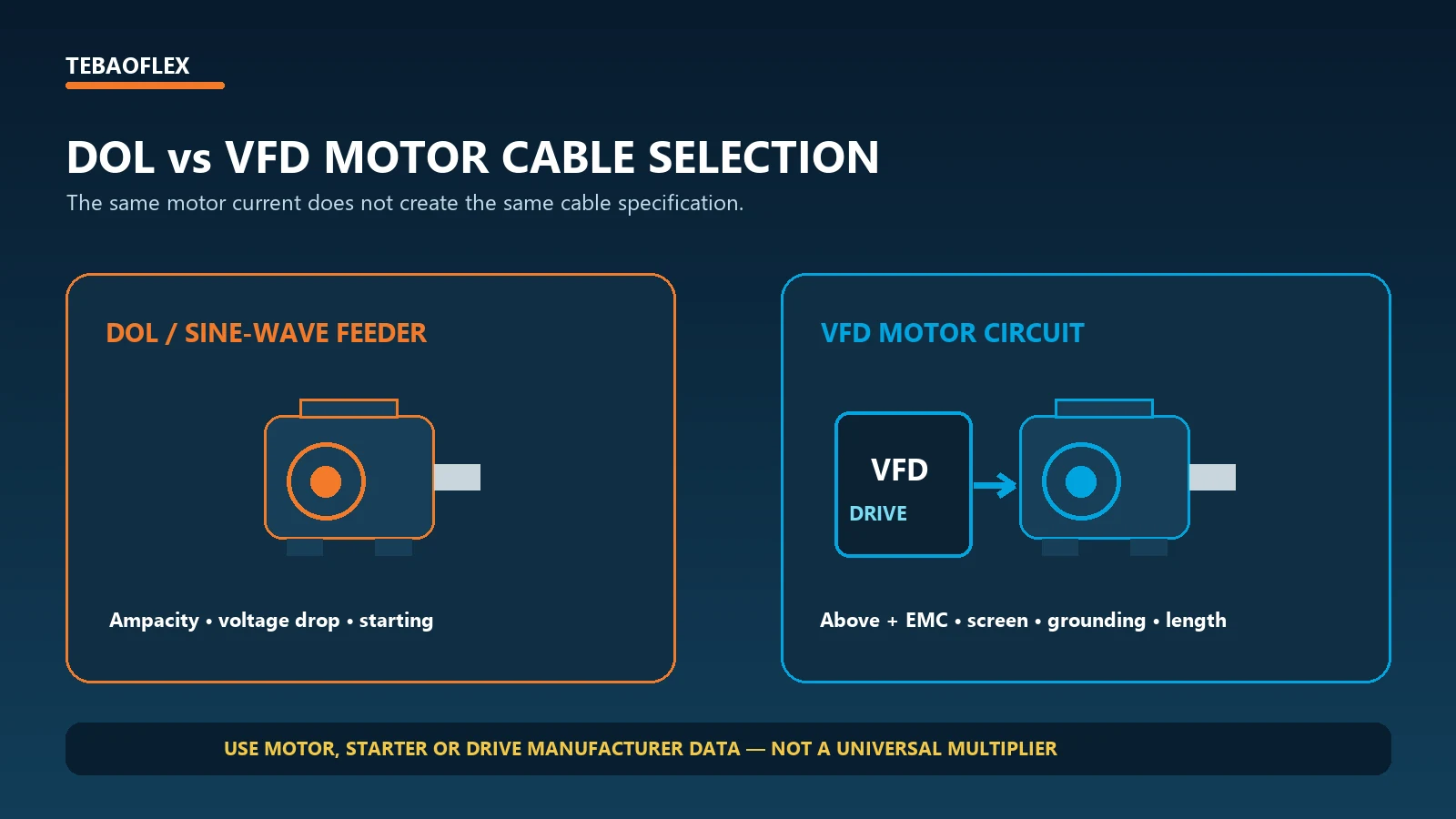
VFD Motor Cable Sizing Is Different
When a frequency converter supplies the motor, conductor size is only one part of the specification. Review drive output current, overload profile, cable length, screen construction and termination, protective earth arrangement, cable capacitance, switching effects, motor insulation and any drive-manufacturer limits. Filters or reactors may be required in some systems.
NEMA’s current Application Guide for AC Adjustable Speed Drive Systems treats the drive, three-phase motor and associated components as a system. That is a better model than assuming that a sine-wave motor feeder and VFD output cable are interchangeable.
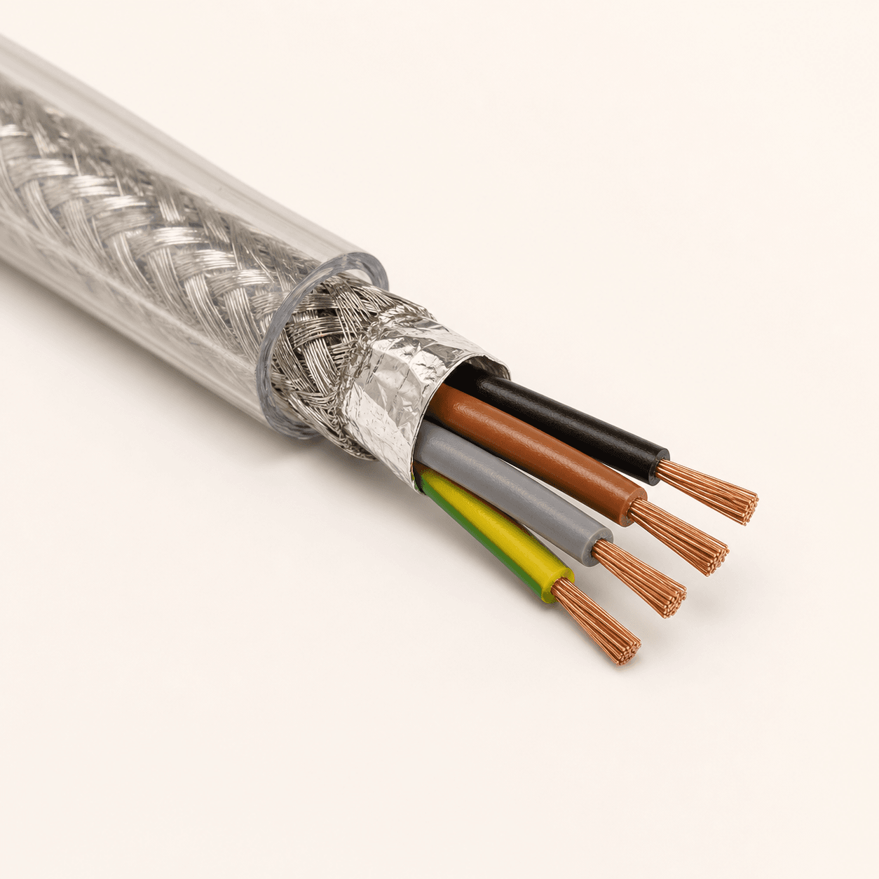
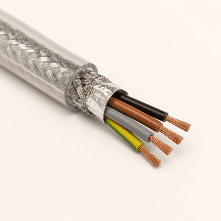
The 2YSLCY-JB motor cable uses Class 5 copper conductors, PE core insulation, foil screening and a tinned-copper braid under a transparent PVC sheath. It is listed for 600/1000 V frequency-converter and servo connections, including pumps, fans and conveyors. It is an application-family example, not an automatic choice from motor kW alone.
Cable Length and Motor Voltage Drop
A 20 m, 100 m and 200 m motor circuit with the same running current do not have the same impedance. Longer routes normally increase running voltage drop and can also worsen starting voltage at the motor terminals. Review cable length and voltage drop before accepting the thermal minimum size.
IEC 60364-5-52 addresses selection and erection of low-voltage wiring systems, including cable-sizing and voltage-drop considerations. Confirm the adopted edition and national implementation; the IEC consolidated edition includes the current amendment information.
Flexible and Screened Motor Cables for Moving Equipment
A moving motor circuit must carry the electrical load while surviving the machine. Cranes, mining equipment, conveyor trolleys, cable chains and mobile machinery may impose bending, tension, acceleration, abrasion, oil, UV and travel-speed requirements. The BUFLEX-M flexible industrial power cable is a 0.6/1 kV Class 5 copper, XLPE-insulated, PUR-sheathed construction with published phase-conductor configurations from 25 to 240 mm².
Upsizing a BUFLEX-M configuration from 50 to 95 mm² does more than reduce electrical resistance: published outer diameter, weight and dynamic bend radius also increase. That mechanical change must be checked against the machine, cable support and available route space.
When the circuit needs both screening and energy-chain movement, the screened energy-chain cable (N)GRDGCGOEU is a 0.6/1 kV application-family example with Class 5 conductors and an overall tinned-copper braid. Chain dimensions, travel distance, speed, bend radius and environmental conditions still need project review.
Fixed Motor Cable vs Flexible Motor Cable vs VFD Cable
| Application | Main cable concerns |
|---|---|
| Fixed DOL motor | Ampacity, voltage drop, starting performance and environment |
| Fixed VFD motor | Above, plus EMC, screen termination, drive compatibility and length |
| Moving motor | Electrical checks plus repeated bending, tension, abrasion and weight |
| Moving VFD motor | Electrical, EMC and dynamic mechanical duty together |
For a broader product-level decision process covering voltage, current, material, standards and environment, use the industrial cable selection guide.
Common Three-Phase Motor Cable Sizing Mistakes
- Selecting cable directly from motor kW: power alone does not establish current or installation conditions.
- Ignoring nameplate current: a generic estimate should not replace verified motor data.
- Ignoring PF or efficiency: preliminary output-power calculations require both.
- Using a universal motor cable chart: a chart without voltage, construction, installation, temperature and length assumptions is incomplete.
- Checking ampacity but not voltage drop: long feeders may require a larger conductor for motor-terminal performance.
- Ignoring starting conditions: the motor may not accelerate satisfactorily even when running ampacity passes.
- Using ordinary power cable on a VFD without an EMC review: screening, grounding, capacitance and drive limits can matter.
- Upsizing without checking mechanical effects: larger moving cables weigh more and need more bend and route space.
Three-Phase Motor Cable Selection Checklist
| Parameter | What to provide |
|---|---|
| Motor power | kW or hp; input or output basis |
| Motor current | Verified nameplate rated A |
| Voltage and frequency | For example 400 V, 50 Hz or 480 V, 60 Hz |
| Starting method | DOL, star-delta, soft starter or VFD model |
| PF and efficiency | Required if current must be calculated |
| Cable length | Actual one-way routed distance |
| Installation | Tray, conduit, free air, ground or machine |
| Ambient | Maximum expected °C and nearby heat sources |
| Cable duty | Fixed, flexible, drag chain, festoon or reeling |
| VFD and screening | Drive data and required EMC arrangement |
| Environment | Oil, UV, water, abrasion or chemical exposure |
| Standard | IEC, NEC, national or project requirement |
Frequently Asked Questions
How do you calculate cable size for a three-phase motor?
Start with verified rated current, establish design current, select the applicable ampacity data, apply derating, choose a candidate conductor, then check running and starting voltage drop, fault duty, protection and cable construction.
What cable size do I need for a 15 kW three-phase motor?
There is no universal size. Confirm voltage, nameplate current, length, installation, ambient temperature, starting method and cable type, then complete the sizing process.
What cable size do I need for a 30 kW motor?
The worked example estimates 54.1 A at 400 V with PF 0.86 and efficiency 0.93, but that does not establish a universal mm² size. Use actual nameplate current and the applicable ampacity and voltage-drop method.
Should I use motor kW or nameplate amps to size the cable?
Use verified motor nameplate current when available. Convert kW to estimated current for preliminary design or a reasonableness check, not as a replacement for the selected motor’s data.
Does a 480 V motor need the same cable as a 400 V motor of the same kW?
Not necessarily. The higher-voltage motor generally draws less current for the same power basis, but final size still depends on the actual motor, installation, length, standard and cable construction.
Does motor starting current require a larger cable?
Not automatically. Continuous ampacity and temporary starting performance are different checks. Starting voltage drop, acceleration and protection coordination can nevertheless influence the final design.
Does cable length affect motor cable size?
Yes. A long route increases impedance and voltage drop. The thermal minimum size may need to be increased to maintain acceptable voltage during running or starting.
Does a VFD motor require a special cable?
It depends on the drive, motor and installation, but VFD circuits commonly require review of screening, EMC, grounding, capacitance, cable length and manufacturer requirements beyond ordinary ampacity sizing.
Can I use a three-phase motor cable size chart directly?
Only when its voltage, current basis, cable construction, conductor material, installation, temperature, length and standard match the project. Otherwise it is only a preliminary screening reference.
Need Help Selecting Cable for a Three-Phase Motor?
Send TEBAOFLEX the motor nameplate or motor power, rated voltage, rated current, frequency, starting method or VFD model, cable route length, installation method, ambient temperature and whether the cable is fixed or moving. Our team can review the electrical load together with voltage drop, EMC and mechanical cable requirements before confirming a suitable construction.
Technical review basis: U.S. Department of Energy motor guidance; NEMA MG 1 motor and inverter-fed motor information; NEMA guidance for AC adjustable-speed drive systems; IEC 60364-5-52:2009+AMD1:2024; verified TEBAOFLEX product data; and the linked calculation guides. Updated September 28, 2026. Examples are instructional estimates. Final design must follow the selected motor, starter or drive manufacturer’s data, applicable code, product marking and project engineering requirements.