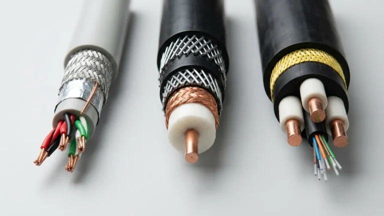
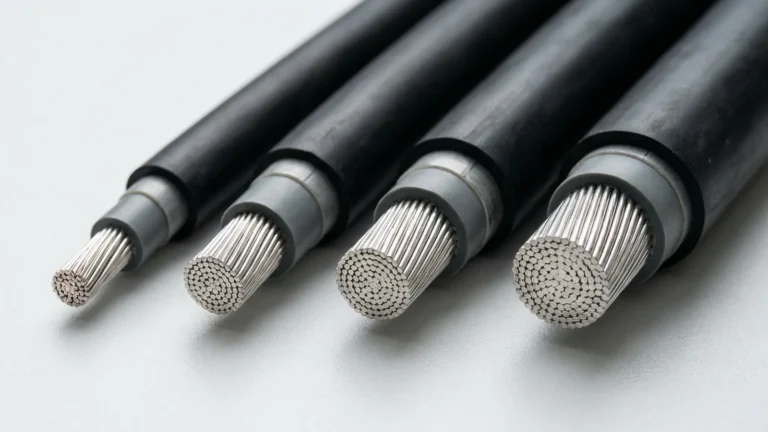
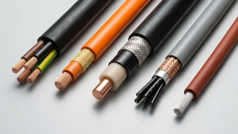
Engineering summary: In international cable standards (IEC 60038, IEC 60502, DIN VDE 0250), Low Voltage (LV) covers AC ratings up to 1,000 V (0.6/1 kV), Medium Voltage (MV) spans above 1 kV up to 35 kV (such as 3.6/6 kV, 6/10 kV, 8.7/15 kV, 12/20 kV, and 18/30 kV), and High Voltage (HV) starts above 35 kV. North American ANSI/NEC specifications express cable ratings by single phase-to-phase class (600 V to 35 kV) paired with 100%, 133%, or 173% insulation levels.
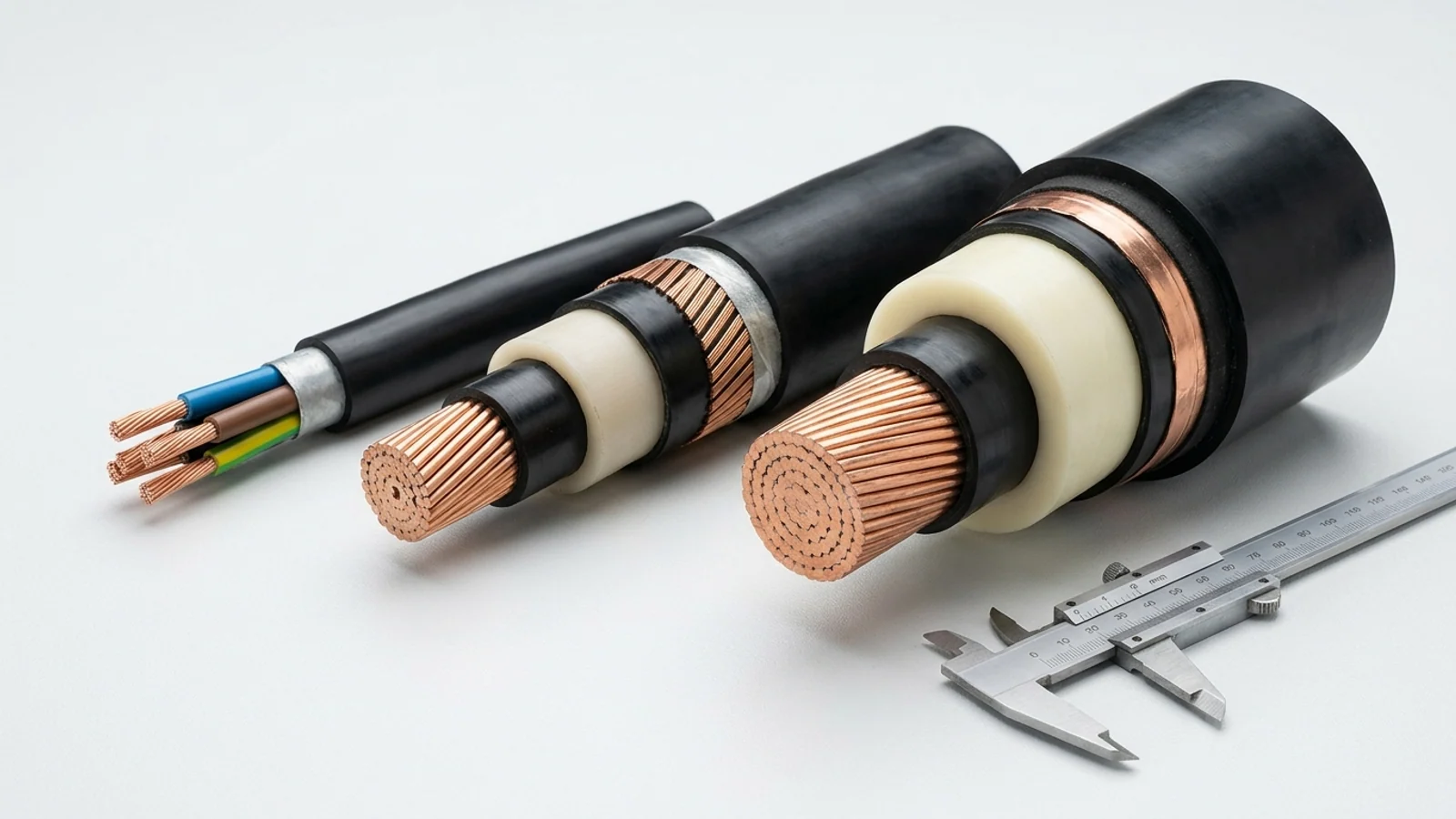
Cross-border industrial projects frequently stall when an EPC specification calls for a North American 4,160 V or 13.8 kV feeder and the equipment vendor quotes an IEC/VDE 3.6/6 kV or 8.7/15 kV reeling cable—or when a technician casually labels any 6.6 kV crane supply as “high voltage.” Misreading cable voltage designations leads to under-insulated dielectric breakdown on unearthed/impedance-grounded mining networks or mismatched medium-voltage terminations.
What Are the Standard Voltage Ranges for LV, MV and HV Cables?
Under IEC and IEEE industrial power conventions, low-voltage cables operate up to 1 kV AC (1.5 kV DC), medium-voltage cables cover 1 kV to 35 kV AC for primary plant distribution, mining excavators, and port cranes, and high-voltage cables operate above 35 kV up to 230 kV for grid transmission.
Note an important safety-code nuance: regulatory installation rules such as the EU Low Voltage Directive (2014/35/EU) or OSHA safety rules often refer to everything above 1,000 V AC simply as “high voltage” for arc-flash and personnel clearance purposes. In cable manufacturing and dielectric engineering, however, separating Medium Voltage (1.8/3 kV through 18/30 kV) from transmission-class High Voltage (>35 kV) is essential because MV elastomeric cables use extruded EPR/XLPE triple-layer insulation suitable for flexible reeling and trailing.
| Voltage Tier | IEC / DIN VDE Designations (U0/U) | US NEC / ICEA / UL Classes | Dielectric & Field Control Construction | Typical Industrial Equipment |
|---|---|---|---|---|
| Control & Light LV (≤500 V) | 300/300 V, 300/500 V | 300 V (UL PLTC, SJOOW, AWM) | Single-layer PVC, PUR, TPE, or silicone insulation; optional EMC copper braid | PLC cabinets, sensor loops, portable hand tools (YY / YSLY 300/500V) |
| Heavy Industrial LV (600 V – 2 kV) | 450/750 V, 0.6/1 kV (Um = 1.2 kV), 0.69/1.15 kV, 1.8/3 kV | 600 V (SOOW, Type W), 1,000 V, 2,000 V (DLO, Type G-GC) | Heavy-wall EPR (3GI3), HEPR, or XLPE insulation without semiconductive stress layers | VFD motors, switchgear jumpers, welders, underground shuttle cars (H07RN-F, 2 kV DLO) |
| Medium Voltage (MV) (3.3 kV – 35 kV) | 1.9/3.3 kV, 3.6/6 kV, 6/10 kV, 8.7/15 kV, 12/20 kV, 18/30 kV | 5 kV, 8 kV, 15 kV, 25 kV, 35 kV (Type SHD-GC, Type MV-105) | Triple-extruded inner conductor screen + MV EPR/XLPE dielectric + outer insulation screen + metallic shield | STS container cranes, bucket-wheel excavators, TBMs, dredgers ((N)TSCGEWÖU, Type MV-105) |
| High Voltage (HV) & Pulse Specialty | >36 kV AC power; 7 kV to 25 kV DC/pulse ignition | 46 kV – 230 kV transmission; 10 kV – 25 kV GTO/igniter | Thick-wall XLPE/fluid-filled power; or corona-resistant silicone/FEP for high-voltage low-current ignition | Substation grid links; refinery flare-stack & furnace igniters (25 kV Flare Igniter Wire) |
How Do You Read IEC and DIN VDE Voltage Ratings: U0 / U (Um)?
In an IEC or DIN VDE cable rating written as U0 / U (Um)—for example 6/10 (12) kV—U0 is the rated RMS power-frequency voltage between any phase conductor and earth or metallic screen, U is the rated RMS voltage between any two phase conductors, and Um is the highest sustained system voltage permitted.
- Why 450/750 V and 0.6/1 kV differ on VDE rubber cables: Harmonized H07RN-F carries a nominal rating of 450/750 V under EN 50525-2-21, though DIN VDE 0298-3 permits protected fixed-installation operation up to 0.6/1 kV under specific mechanical protection conditions. True heavy-duty mining cables such as NSSHÖU (DIN VDE 0250-812) are natively built and factory-tested at 0.6/1 kV (with higher AC dielectric test voltage of 3,000 V to 4,000 V).
- DIN VDE 0250 elevated mining voltage window: German reeling and trailing standards (DIN VDE 0250-813) permit a higher maximum three-phase operating voltage tolerance than standard fixed distribution cables—for instance, a 3.6/6 kV (N)TSCGEWÖU cable has a maximum permitted three-phase operating voltage Um of 7.2 kV, and a 6/10 kV build permits up to 12 kV.
- Isolated neutral (IT) and impedance-earthed systems: Under IEC 60502-2 Category C (systems where a single earth fault is not cleared within 1 minute and can persist up to 8 hours), phase-to-earth healthy-phase voltage rises to full phase-to-phase voltage. In such networks, a 6.6 kV unearthed system often requires a 6/10 kV cable (where U0 = 6 kV) rather than a 3.6/6 kV cable (where U0 = 3.6 kV).
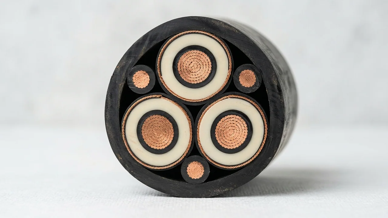
Where U0 and U Act Inside a Screened MV Core
- Radial Phase-to-Screen Stress (U0): Acts directly across each phase’s cream EPR dielectric wall—between the inner conductor semicon ring and the grounded outer semicon/copper wire screen.
- Phase-to-Phase Voltage (U): Governs system line voltage across the three symmetrical phase cores; on individually screened MV cables, radial thickness is sized primarily by U0 and earth-fault duration.
- Split Interstitial Earths: Three outer copper cores maintain continuous low-impedance protective earth and pilot monitoring.
Ground-fault voltage rise check: Before ordering a medium-voltage mining or marine cable, always confirm whether your transformer neutral is solidly earthed, low-resistance grounded, or high-impedance/unearthed (IT). Selecting U0 = 3.6 kV on an ungrounded 6.6 kV system exposes the phase insulation to 1.73× its continuous phase-to-screen design stress during an earth fault.
How Do US and North American Industrial Voltages Map to IEC Cable Ratings?
North American power systems (ANSI C84.1 / NEC NFPA 70) use nominal three-phase voltages such as 480 V, 600 V, 2,400 V, 4,160 V, 6,900 V, 12,470 V, 13,800 V, and 34,500 V, specifying cable dielectric thickness through 100%, 133%, or 173% Insulation Levels rather than dual U0/U numbers.
Under UL 1072 and ICEA S-93-639 / S-75-381, Insulation Level depends on ground-fault clearing time: 100% level applies where ground faults are cleared within 1 minute; 133% level applies where clearing takes up to 1 hour (standard on most resistance-grounded mining and petrochemical feeders); and 173% level applies to ungrounded systems with indefinite fault duration. For wider regulatory differences, see our IEC vs NEC cable standards comparison.
| US / North American System Voltage | Standard NEC / ICEA Cable Class | Closest IEC / DIN VDE Cable Rating | Engineering Cross-Reference Note |
|---|---|---|---|
| 120/208 V, 277/480 V, 347/600 V | 600 V (SOOW, Type W, THHN/XHHW-2) | 450/750 V or 0.6/1 kV | 0.6/1 kV exceeds 600 V dielectric geometry, but check UL/CSA/MSHA listing requirements if installed under NEC/CEC jurisdiction |
| 480 V – 1,000 V Heavy Mining / VFD | 2,000 V (2 kV DLO, Type G-GC, SHD-GC) | 0.6/1 kV or 1.8/3 kV | 2 kV DLO and Type G-GC provide heavy EPR wall thickness for mechanical puncture margin even on 480 V or 995 V mine faces |
| 2.4 kV & 4.16 kV Three-Phase | 5 kV (100% or 133% Insulation Level) | 3.6/6 kV (Um = 7.2 kV) | 3.6/6 kV (U0 = 3.6 kV) covers 4.16 kV grounded/resistance-grounded duty; verify connector kit diameter range |
| 6.6 kV & 6.9 kV Three-Phase | 8 kV (100% or 133% Insulation Level) | 6/10 kV (Um = 12 kV) | Standard for Japanese/Asian STS port cranes (6.6 kV) and UK/Commonwealth coal faces (3.8/6.6 kV BS 6708) |
| 11 kV, 12.47 kV, 13.2 kV & 13.8 kV | 15 kV (100% or 133% Insulation Level) | 8.7/15 kV (Um = 17.5 kV) or 12/20 kV | For 13.8 kV systems with delayed earth-fault tripping, step up to 15 kV 133% (ICEA) or 12/20 kV (IEC/VDE) |
| 20 kV, 22 kV & 33 kV / 34.5 kV | 25 kV & 35 kV (Type MV-105 / SHD-GC) | 12/20 kV & 18/30 kV (Um = 36 kV) | Requires strict partial-discharge factory routine testing and matched cold-shrink or slip-on stress cones |
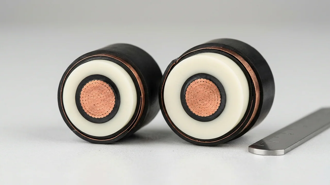
Why Do Medium-Voltage Cables Above 2 kV Require Semiconductive and Metallic Screens?
Above approximately 2 kV to 3.3 kV, microscopic air gaps between a stranded copper conductor and the surrounding rubber insulation ionize under intense electric fields, generating ozone and partial discharge (corona) that erode insulation from the inside out unless controlled by bonded semiconductive layers and metallic earth screens.
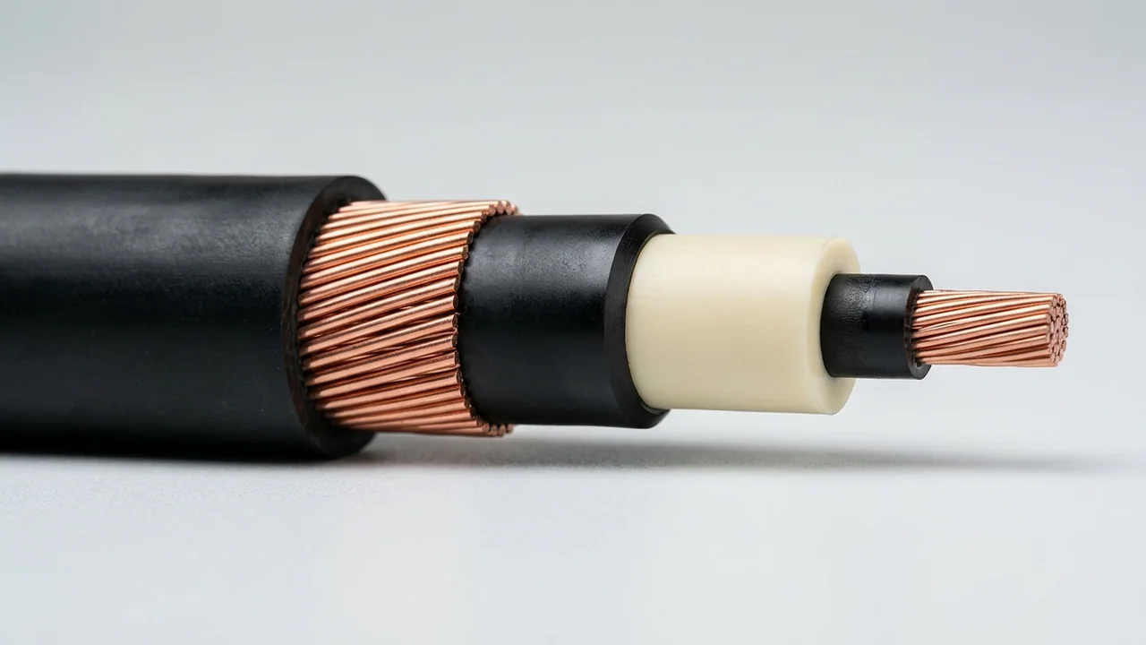
5-Step MV Stress-Control Layer Sequence (Right to Left)
- Class 5 Copper + Inner Semicon: Smooths stranded wire scallops into a uniform cylindrical electrode.
- Void-Free 3GI3 EPR Dielectric: Triple-extruded and cross-linked simultaneously with both semicon screens.
- Strippable Outer Semicon: Confines electric stress cleanly inside the EPR wall for corona-free termination.
- Helical Copper Wire Screen: Drains capacitive charging current and carries earth-fault current (check I²t capacity).
- Heavy Elastomer Outer Jacket: Protects the screen assembly against abrasion, oil, and water ingress.
Frequently Asked Questions
Can I use a 0.6/1 kV cable on a 690 V industrial VFD motor circuit?
Nominal phase-to-phase voltage of 690 V falls within 0.6/1 kV (Um = 1.2 kV) for sinusoidal AC power, but PWM variable-frequency drives generate high-frequency voltage reflections (up to 2× DC bus peaks). On 690 V VFDs, specify symmetrical screened VFD cables or step up to 1.8/3 kV EPR-insulated cables to prevent premature corona breakdown.
What does 133% insulation level mean on a US 5 kV or 15 kV cable?
Under UL 1072 and ICEA standards, a 133% insulation level increases the radial dielectric wall thickness (for example, from 90 mils / 2.29 mm at 100% level to 115 mils / 2.92 mm at 133% level on 5 kV MV-105) so the cable can safely withstand phase-to-phase voltage stress on the healthy phases for up to 1 hour during an uncleared single line-to-ground fault.
Is 3.6/6 kV cable suitable for a 6.6 kV port crane power supply?
Only if the 6.6 kV network is effectively earthed and the governing standard (such as DIN VDE 0250-813 with Um = 7.2 kV) explicitly covers 6.6 kV operation. Where the port substation uses high-impedance or isolated neutral earthing, or where JIS 6600V 3PNCT / IEC Category C applies, specify a 6/10 kV rated reeling cable.
Does higher cable voltage rating increase current-carrying capacity (ampacity)?
No. Voltage rating dictates insulation thickness and dielectric stress control, whereas continuous current rating depends on conductor cross-section, maximum permissible conductor temperature, ambient heat dissipation, and drum/grouping derating. In fact, much thicker MV insulation slightly slows radial heat transfer.
Confirm Your LV or MV Cable Voltage Rating Before Ordering
Whether you are specifying a 450/750 V portable rubber feeder, a 2 kV North American mining cable, or an 8.7/15 kV to 18/30 kV port crane reeling cable, TEBAOFLEX engineers review system voltage, neutral earthing, and termination compatibility prior to production.
- Nominal system voltage (e.g., 480 V, 690 V, 3.3 kV, 4.16 kV, 6.6 kV, 11 kV, 13.8 kV, 20 kV) and frequency (50/60/400 Hz).
- System neutral earthing method (solidly grounded, resistance-grounded, or isolated IT) and fault clearing time.
- Target standard (DIN VDE 0250, IEC 60502, BS 6708, UL 1072 MV-105, or ICEA SHD-GC) and required length.
Standards & technical references: IEC 60038 (IEC standard voltages); IEC 60502-1 & IEC 60502-2 (Power cables with extruded insulation from 1 kV up to 30 kV, Categories A, B, and C); DIN VDE 0250-812 & 0250-813 (Flexible rubber trailing and reeling cables); ANSI C84.1, UL 1072 & ICEA S-93-639 / S-75-381 (Medium-voltage power and portable mining cables).