Heat Exposure
State ambient, radiant, localized or direct heat and distinguish normal from peak temperature.

TEBAOFLEX provides high-temperature and application-specific cable solutions for furnaces, industrial heaters, foundries, ignition systems and heat-exposed electrical equipment. Cable construction is selected according to operating temperature, circuit function, voltage, installation route and exposure to heat, chemicals and mechanical stress.
The same temperature can require very different conductor, insulation, protection and screening systems. A useful specification describes the real heat source, circuit function, installation route and combined environmental stresses.
State ambient, radiant, localized or direct heat and distinguish normal from peak temperature.
Define power, control, signal, internal wiring, high voltage or ignition duty.
Confirm fixed, flexible or internal-equipment routing, available space and mechanical protection.
Identify oil, chemicals, abrasion, dust, metal scale, EMI and any repeated movement.
Begin with the equipment and cable route. Furnace wiring, foundry machinery, burners and compact electrical assemblies may share a heat requirement while needing completely different electrical and mechanical constructions.
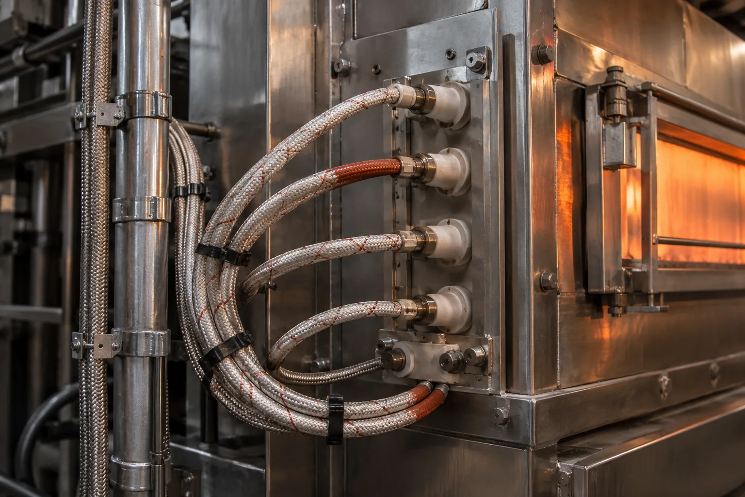
Heat-treatment furnaces, ovens, kilns and heating chambers require review of sustained or radiant heat, fixed routing, voltage and mechanical protection.
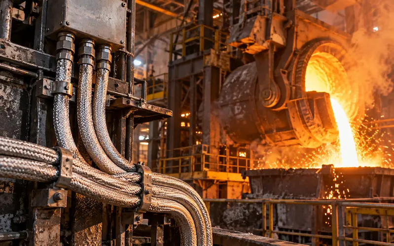
Steel mills, foundries, casting equipment and rolling lines can combine heat with dust, scale, abrasion, oil and mechanical impact.
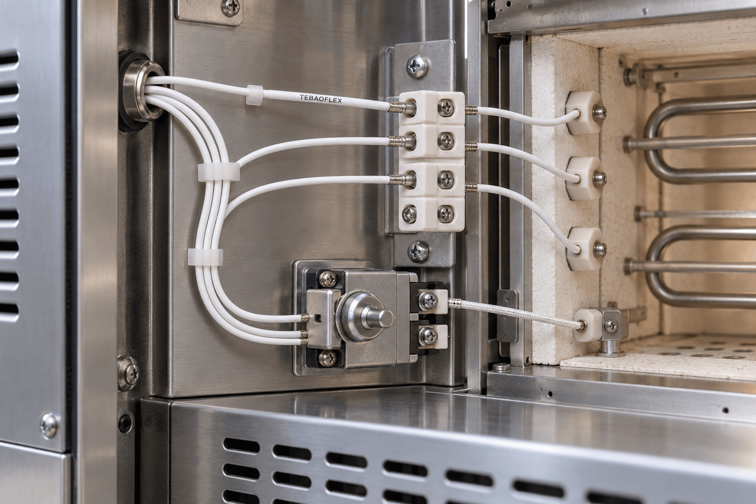
Electric heaters, dryers and process-heating equipment need compact wiring selected for temperature class, voltage, insulation and connection method.
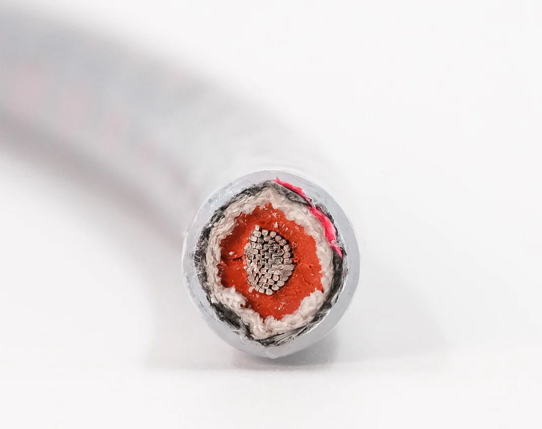
Industrial burners, boilers, process heaters and flare systems require the voltage, ignition duty, heat and chemical exposure to be assessed together.
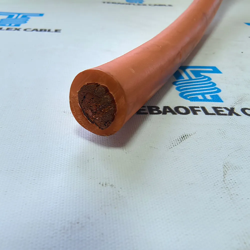
Motors, generators and heating machinery may need flexible conductors and heat-resistant insulation within a compact equipment route.
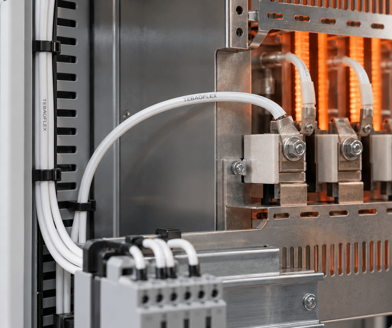
Heating appliances, lighting, power electronics and control assemblies may require UL-style PFA, PTFE, FEP or ETFE hook-up wire.
“Need 200°C cable” is not yet a complete specification. Clarify whether the stated value is ambient temperature, conductor temperature or a nearby surface temperature, then describe the duration and location of the heat.
The complete cable route remains in a hot enclosure, oven area or heated cabinet for the defined operating period.
The route passes near a heating element, burner, exhaust or hot pipe. Distance, shielding and routing influence the exposure.
Furnace, foundry or ignition zones can require mica, glass fibre, plated conductors or another project-specific thermal barrier.
Flexing, chemicals, abrasion, high voltage or EMI can change the suitable material system even at the same temperature.
A heat-resistant power lead, screened sensor cable and 25 kV igniter wire solve different problems. The circuit function should be fixed before comparing insulation materials or temperature labels.
For heating equipment, motors and industrial machinery using a confirmed silicone or fluoropolymer construction.
For ignition and special electrical systems requiring coordinated voltage, insulation thickness, heat and termination design.
For burners, flare systems and igniters where high voltage, severe heat and environmental exposure act together.
For temperature control, sensors and machine circuits needing multicore layouts, screening or EMI control.
For appliance, electronic, lighting and compact equipment routes using a documented hook-up wire style.
For equipment needing a custom combination of conductor, insulation, outer protection, shielding and marking.
Industrial furnaces, heat-treatment systems, ovens, dryers, kilns, heaters and thermal-processing equipment often contain several temperature zones. The cable route may begin in a cooler cabinet, pass near a hot surface and terminate at a heating element or sensor.
Selection therefore includes normal and peak temperature, conductor material, insulation and outer protection, installation route, mechanical protection and voltage. A silicone and glass-fibre construction such as SiAF-GL is one possible starting point for documented fixed industrial wiring; it should not be applied to every furnace route without reviewing the exact duty.
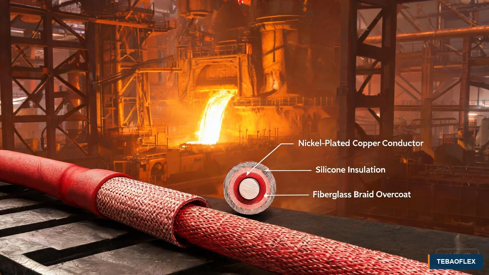
Steel mills, foundries, smelting furnaces, casting lines, heat-treatment equipment and hot rolling areas expose wiring to more than temperature. Dust, metal scale, abrasion, oil, mechanical impact and occasional movement can be equally important.
Temperature resistance is only one part of the specification. Cable routing, trays, conduits, protective sleeves, glands and the distance from radiant heat should be reviewed with the conductor and insulation system. Where movement occurs, confirm that the selected construction supports that motion rather than assuming every heat-resistant wire is also a continuous-flex cable.
Industrial burners, boilers, flare stacks, process heaters and gas ignition systems combine high voltage with heat and potentially chemical exposure. The cable must be selected for the ignition voltage, pulse or continuous electrical duty, routing, bend requirement, outer protection and termination.
Representative products include the 25 kV fiberglass-jacket igniter wire and the 25 kV flare-stack ignition cable. Their constructions are application-specific and should be compared against the burner, flare and project requirements.
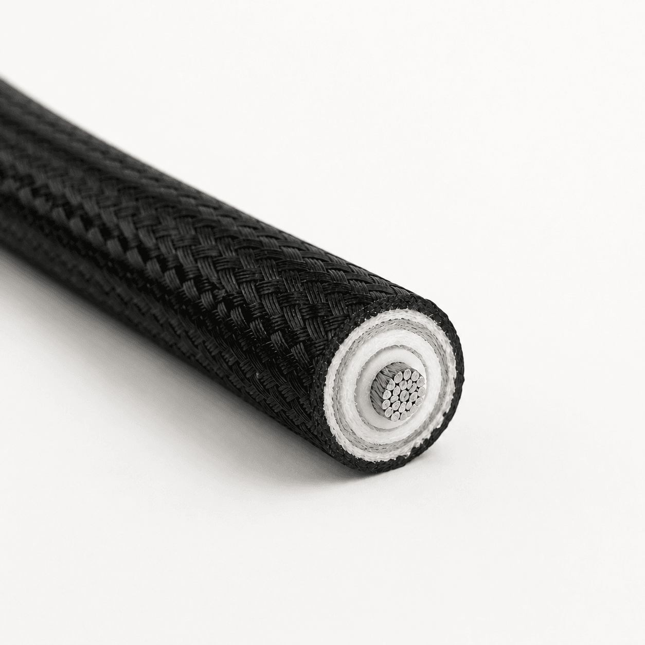
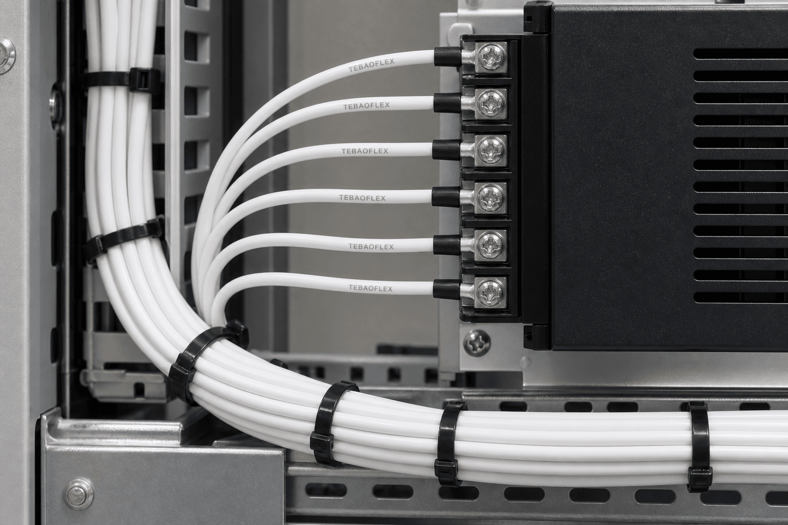
Appliances, lighting equipment, heaters, motors, generators and power electronics often need compact single-core wiring with a documented voltage and temperature class. Routing space, terminal design, conductor plating, insulation thickness and the applicable UL style or project standard are part of the selection.
Do not select an internal-equipment wire from material name alone. PFA, PTFE, FEP, ETFE and silicone systems can be manufactured in different voltage, temperature and conductor configurations. Use the exact product data for the chosen style and size.
Temperature-control systems, sensors and machine controls may need multicore conductors, twisted arrangements, an overall braid or another screening concept. Heat resistance does not replace EMC design: the signal level, interference source, screen coverage, grounding method and routing beside power cables must be considered.
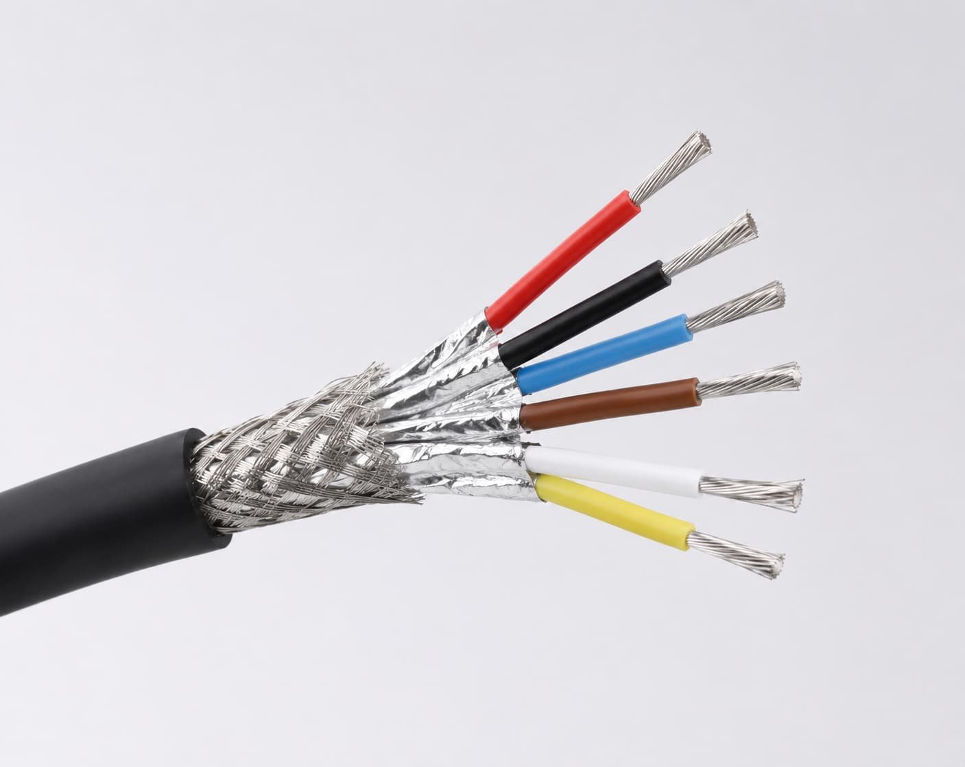
Material names are useful starting points, but the allowable temperature and application boundary depend on the complete cable construction, conductor, standard and installation. The table compares design roles without assigning one universal rating to every material.
| Material System | Design Characteristics | Typical Starting Application | Selection Note |
|---|---|---|---|
| Silicone rubber | Flexible, heat-resistant insulation | Industrial heaters, motors and equipment wiring | Confirm voltage, movement and outer protection. |
| Silicone + glass fibre | Heat resistance with braided surface protection | Furnaces and fixed industrial machinery wiring | Review abrasion, route and termination. |
| PFA | Compact fluoropolymer insulation with heat and chemical performance | Appliance and electronic internal wiring | Use the exact UL style or product data. |
| PTFE | Heat and chemical performance in thin-wall specialty wiring | Equipment and hook-up wire | Confirm conductor plating and mechanical duty. |
| FEP | Fluoropolymer insulation for selected equipment wiring | Control, lead and internal wiring | Match style, voltage and temperature. |
| ETFE | Tough compact fluoropolymer insulation | Industrial and electronic wiring | Check the actual product construction. |
| Mica + glass fibre | Thermal barrier and severe-heat protection | Ignition, furnace and severe heat zones | Review flexibility, voltage and handling. |
Use the matrix to identify a cable family to investigate first. Final selection requires the exact operating temperatures, voltage, circuit role, route, environmental exposure and documentation.
| Application | Main Exposure | Electrical Duty | Recommended Starting Family |
|---|---|---|---|
| Industrial furnace | Sustained or radiant heat | Power | Silicone / glass-fibre cable |
| Industrial oven | Elevated temperature | Power / control | Silicone cable |
| Heating element | Localized heat | Power | Silicone or PFA wire |
| Foundry equipment | Heat + abrasion | Power / control | Glass-fibre specialty cable |
| Burner system | Heat | Ignition | HV ignition wire |
| Flare stack | Heat + chemicals + HV | Ignition | Flare-stack cable |
| Motor / generator | Heat | Power | Silicone flexible cable |
| Temperature control | Heat + EMI | Signal / control | Screened high-temperature cable |
| Appliance internal wiring | Elevated heat | Power / signal | UL PFA / PTFE wire |
| Compact electronics | Heat + limited space | Internal wiring | PFA / FEP / ETFE wire |
A nominal temperature is one input, not an application approval. Correct cable construction results from the combined thermal, electrical, mechanical and environmental duty.
Separate ambient, conductor and nearby surface temperatures, then define duration and thermal cycling.
A 250°C hook-up wire is not automatically suitable for high-voltage ignition or screened sensor circuits.
Heat resistance does not automatically provide continuous-flex, chemical, abrasion or direct-flame capability.
These representative products cover different functions and material systems. Review the individual page and confirm the exact style, size, voltage, temperature and installation before specifying a product.
Silicone and glass-fibre single-core cable for documented fixed high-temperature industrial wiring.
View product →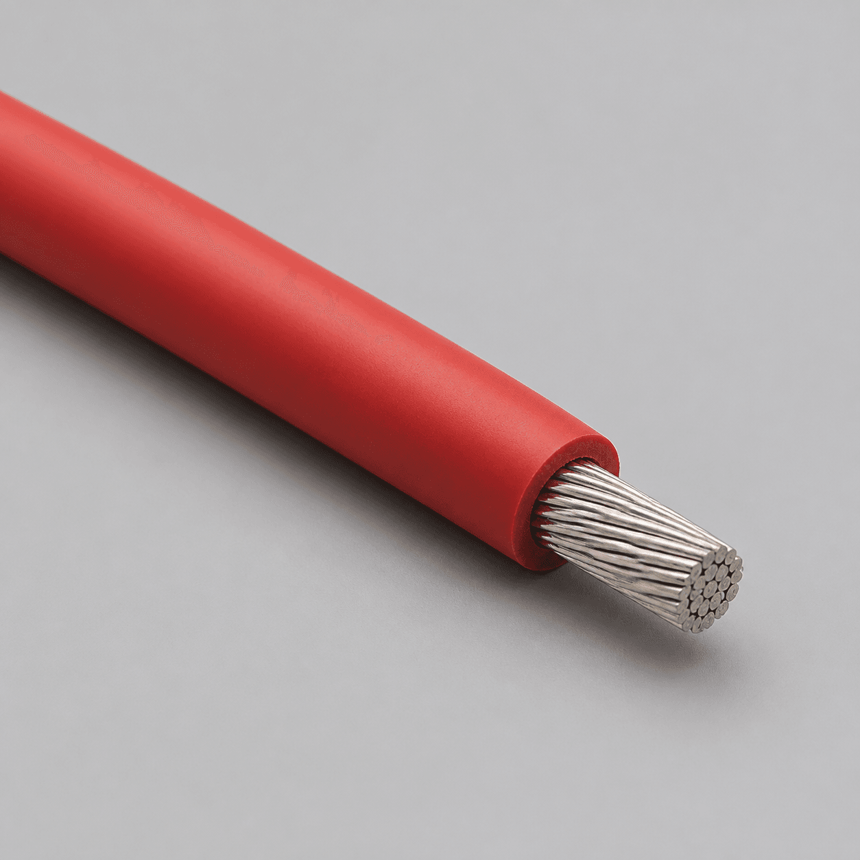
High-voltage silicone construction for selected heat-exposed internal equipment wiring.
View product →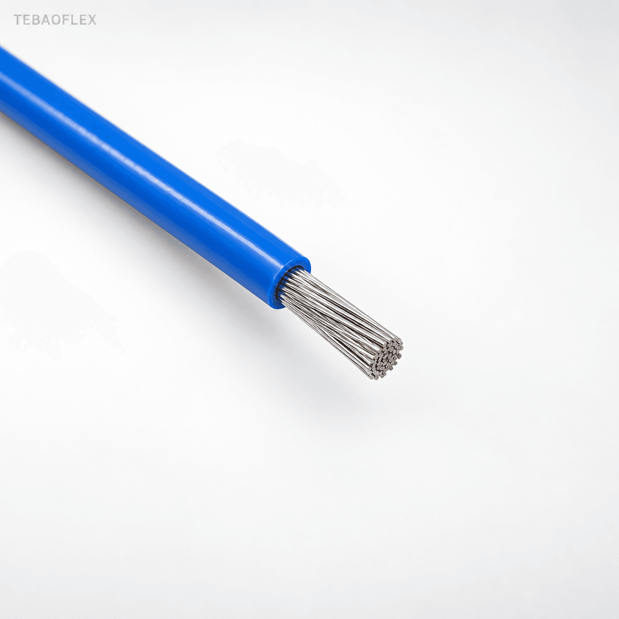
600 V PFA hook-up wire for compatible appliance and electronic equipment applications.
View product →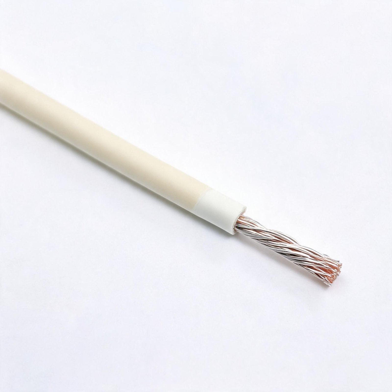
PTFE-insulated 1000 V wire for the documented high-temperature equipment duty.
View product →
Mica and glass-fibreglass wire for the exact UL style and documented severe-heat application.
View product →High-voltage ignition wire with fibreglass outer protection for selected burner systems.
View product →Application-specific cable for confirmed high-temperature flare and ignition-system requirements.
View product →Multicore screened construction for selected high-temperature control and signal circuits.
View product →Required capability depends on the exact construction and application. Confirm each property for the selected cable rather than applying one product’s data to an entire material or category.
Long-duration exposure affects conductor, insulation, braid, sheath and termination choices.
Distance, shielding and route influence exposure near furnaces, burners and hot surfaces.
Repeated heating and cooling can impose different stresses from a stable operating temperature.
Ignition and specialty circuits require voltage-compatible insulation and termination design.
Oil, process chemicals and cleaning agents can change the appropriate insulation or outer protection.
Metal scale, machinery and routing surfaces may require braid, conduit or another mechanical barrier.
Flexibility and dynamic endurance must be confirmed separately from temperature capability.
Control and sensor circuits need screening and installation practices coordinated with the system.
Work from the equipment and circuit toward the thermal, mechanical and environmental details. Explicitly separate ambient, conductor and nearby surface temperatures.
Furnace, heater, burner, motor or electronics.
Power, control, signal or ignition.
State continuous and impulse duty if relevant.
Clarify ambient or conductor temperature.
Describe source, distance, duration and cycling.
Fixed, flexible or internal-equipment wiring.
Oil, chemicals, dust, abrasion and impact.
Signal level, interference and grounding.
Compare conductor, insulation and protection.
UL style, IEC, drawing or project specification.
When a catalogue product does not fit the route, TEBAOFLEX can review an application-specific construction using confirmed thermal, electrical, mechanical and environmental inputs. Existing high-temperature products already use different conductor plating, silicone, fluoropolymer, mica, glass-fibre and shielding combinations; the project review determines which combination is technically relevant.
Customisation should remain tied to a defined product boundary, manufacturing route, test plan and documentation package. Connector or terminal interfaces, overall diameter, bend requirement, colour, marking, length, reel or coil format and destination-market requirements should be included early.
The required evidence should follow the exact cable, size, voltage and project specification. Confirm construction drawings, electrical tests, heat-related test basis, inspection scope and destination-market documents before order approval.
Check conductor, plating, insulation, braid, screen, sheath, dimensions and marking against the agreed design.
Confirm voltage data, conductor size, resistance, insulation and requested product or project test records.
Identify the applicable test basis and operating limits for the selected construction without generalizing one result to all products.
Continue the selection process with guides covering furnaces, ignition, silicone, fluoropolymer materials and temperature interpretation.
Review thermal zones, mechanical protection and the information needed for furnace and steel equipment.
Read guide →Compare circuit function, voltage, heat and installation requirements for specialist cable duties.
Read guide →Use UL style, voltage, temperature and equipment conditions to narrow internal-wiring options.
Read guide →Understand where silicone construction may fit and which additional inputs still require review.
Read guide →Compare material-system roles without treating one material name as a complete cable specification.
Read guide →Clarify operating temperature, cable duty and other conditions before selecting rubber cable.
Read guide →These answers clarify the first engineering and purchasing decisions. Final suitability depends on the exact product data and confirmed project conditions.
First clarify whether the value is ambient temperature, conductor temperature or the surface temperature near the route. Then provide normal, peak and cycling conditions, heat source, duration, circuit function, voltage, installation and environmental exposure.
Silicone, PTFE and PFA are different insulation systems with different flexibility, thickness, mechanical and chemical characteristics. The suitable choice depends on the complete wire construction, voltage, application, conductor, standard and installation rather than material name alone.
Possible starting points include silicone or silicone glass-fibre wiring, but the correct product depends on sustained and radiant heat, route, voltage, conductor size, mechanical protection, chemicals, movement and termination. Severe zones may require a different specialty construction.
Burner and flare systems can require high-voltage ignition wire selected for the ignition voltage, thermal zone, chemical exposure, flexibility, outer protection and termination. A normal heat-resistant power lead is not an automatic substitute.
Some constructions use fine-stranded conductors and flexible insulation, but flexibility does not automatically mean continuous-flex capability. State whether the route is fixed, occasionally moved or repeatedly flexed and provide the bend conditions.
Glass fibre and mica can be used in constructions intended for severe heat, ignition or added thermal protection. Their use should follow the exact voltage, flexibility, abrasion, handling and test requirements rather than a general temperature threshold.
Project-specific multicore and screened constructions can be reviewed when the core count, conductor size, insulation material, temperature, signal type, EMI requirement, installation, chemicals, standard and quantity are defined.
Send equipment, cable function, voltage, conductor size, core count, normal and peak temperature, heat source, fixed or flexible installation, chemical and abrasion exposure, shielding, length, quantity, destination, required standard and available drawings.
Send the thermal, electrical, installation and environmental data together so the technical team can compare a suitable material system, cable family and documentation path.