For engineers and procurement professionals working with North American cable standards, understanding AWG current rating is essential for selecting conductors that safely carry the required load without overheating. The American Wire Gauge (AWG) system is the dominant wire sizing standard in the United States and Canada, used across portable cords, flexible cables, control wiring, and industrial power distribution.
This guide provides a practical AWG wire gauge chart with mm2 cross-section conversions and current ratings, helping B2B buyers bridge the gap between metric (IEC) and AWG (UL/NEC) cable specifications. For specific product configurations, visit our SOOW and SJOOW portable cord product page, where AWG sizing is standard.
What Is AWG (American Wire Gauge)?
The American Wire Gauge system is a standardized wire sizing method developed in the United States for round, solid, non-ferrous conductors. The AWG system uses a numbering scheme where lower numbers indicate larger wire diameters and higher numbers indicate smaller diameters. This inverse relationship is a common source of confusion for engineers accustomed to metric sizing, where larger mm2 values indicate larger conductors.
Key characteristics of the AWG system:
- Gauge range: From 0000 (4/0) AWG, the largest standard size at 107.2 mm2, to 40 AWG, the smallest at 0.005 mm2
- Ratio system: Each 6-gauge decrease doubles the cross-sectional area; each 3-gauge decrease doubles the diameter
- Stranded conductors: AWG sizes apply to both solid and stranded conductors — the AWG number refers to the total cross-sectional area, not the individual strand size
- Standards: AWG is defined under ASTM B258 and referenced in NEC Article 310 for conductor ampacity
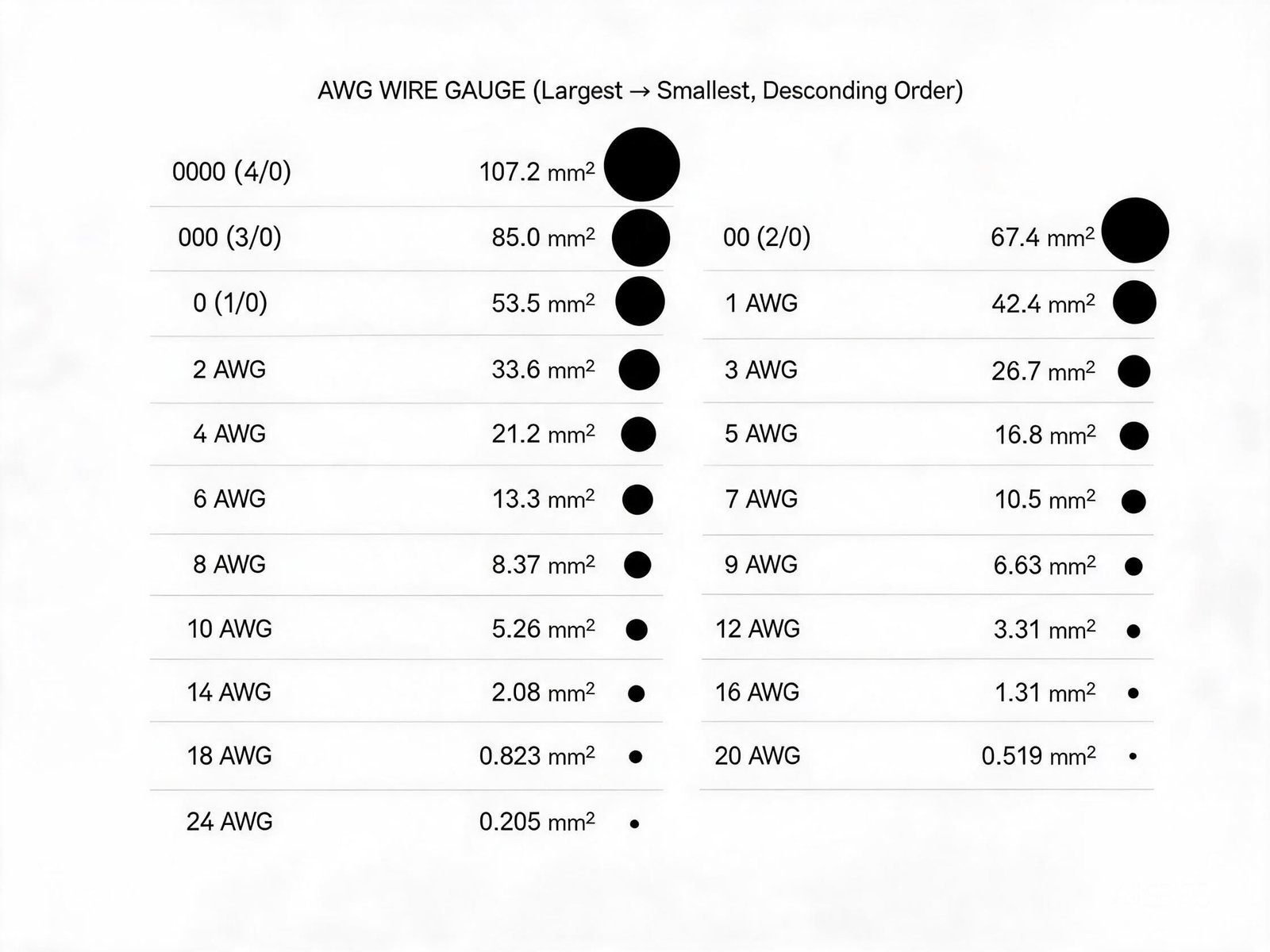
AWG Wire Gauge Chart: Size, mm2, and Current Rating
The following AWG wire gauge chart provides cross-section conversions and approximate current ratings for commonly used industrial cable sizes. The ampacity values are approximate, based on single conductor in free air at 30C ambient temperature with typical rubber insulation. Actual ampacity must be calculated per NEC tables for specific installation conditions.
| AWG | Cross-Section (mm2) | Diameter (mm) | Approx. Ampacity (A) |
|---|---|---|---|
| 0000 (4/0) | 107.2 | 11.68 | 300 |
| 000 (3/0) | 85.0 | 10.40 | 260 |
| 00 (2/0) | 67.4 | 9.27 | 225 |
| 0 (1/0) | 53.5 | 8.25 | 195 |
| 1 | 42.4 | 7.35 | 150 |
| 2 | 33.6 | 6.54 | 130 |
| 4 | 21.2 | 5.19 | 95 |
| 6 | 13.3 | 4.12 | 65 |
| 8 | 8.37 | 3.26 | 50 |
| 10 | 5.26 | 2.59 | 35 |
| 12 | 3.31 | 2.05 | 25 |
| 14 | 2.08 | 1.63 | 20 |
| 16 | 1.31 | 1.29 | 15 |
| 18 | 0.823 | 1.02 | 10 |
| 20 | 0.519 | 0.81 | 5 |
| 22 | 0.326 | 0.64 | 3 |
| 24 | 0.205 | 0.51 | 2 |
Note: Ampacity values are approximate reference values for single conductors in free air. Actual ratings depend on insulation type, ambient temperature, number of current-carrying conductors, and installation method. Always consult NEC Table 310.16 or the applicable IEC standard for specific installations.
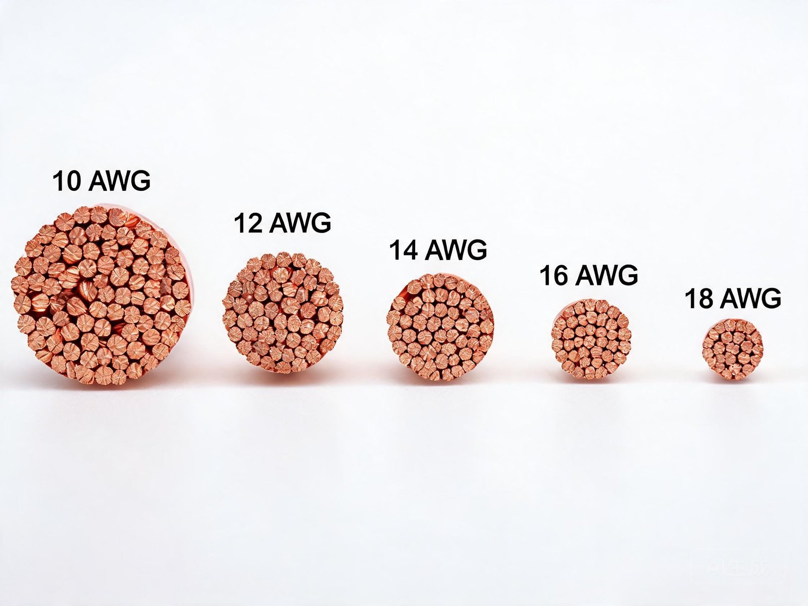
AWG vs Current: Understanding Ampacity
The relationship between AWG vs current is governed by the conductor’s ability to dissipate heat generated by electrical resistance. Larger conductors (lower AWG numbers) have lower resistance per unit length, generating less heat for the same current. However, ampacity is not determined by conductor size alone — multiple factors affect the actual current-carrying capacity:
- Insulation type: Rubber (90C rated) and silicone (200C rated) allow higher ampacity than PVC (75C rated) because the insulation tolerates higher conductor temperatures
- Ambient temperature: Higher ambient temperatures reduce ampacity — NEC tables include temperature correction factors
- Conductor count: Cables with multiple current-carrying conductors require ampacity derating per NEC Table 310.15(C)(1)
- Installation method: Free air allows maximum heat dissipation; conduit, insulation, and burial reduce ampacity
- Duty cycle: Continuous loads require ampacity at 125% of the rated current per NEC Article 210
mm2 to AWG Conversion
For international projects that mix metric and AWG standards, the mm2 to AWG conversion is a routine requirement. The following conversions cover the most commonly encountered sizes:
- 0.35 mm2 to AWG: 0.35 mm2 is approximately 22 AWG (0.326 mm2). The 0.35 mm2 size is commonly used in metric control and signal cables, and 22 AWG is its closest AWG equivalent.
- 0.5 mm2 to AWG: Approximately 20 AWG (0.519 mm2)
- 0.75 mm2 to AWG: Approximately 18 AWG (0.823 mm2)
- 1.0 mm2 to AWG: Approximately 17 AWG (1.04 mm2)
- 1.5 mm2 to AWG: Approximately 16 AWG (1.31 mm2)
- 2.5 mm2 to AWG: Approximately 14 AWG (2.08 mm2)
- 4.0 mm2 to AWG: Approximately 12 AWG (3.31 mm2)
- 6.0 mm2 to AWG: Approximately 10 AWG (5.26 mm2)
- 10 mm2 to AWG: Approximately 8 AWG (8.37 mm2)
- 16 mm2 to AWG: Approximately 6 AWG (13.3 mm2)
- 25 mm2 to AWG: Approximately 4 AWG (21.2 mm2)
The conversion is not exact because AWG uses a logarithmic scale while metric mm2 uses a linear scale. Always select the AWG size with equal or greater cross-sectional area than the required metric size. For a comprehensive range of AWG and metric sized cables, explore our industrial cable product catalog.
24 AWG Cable: Specifications and Applications
24 AWG is one of the most widely used small conductor sizes in industrial applications. With a cross-sectional area of 0.205 mm2 and a diameter of approximately 0.51 mm, 24 AWG conductors are found in:
- Control and signal cables: Instrumentation wiring, sensor connections, and data transmission in industrial automation
- Shielded cables: Individual conductors in multi-pair shielded cables for signal integrity
- Robot cables: Fine-wire 24 AWG conductors in high-flex-life cables for robotic applications
- Servo cables: Signal pair conductors within servo motor power and feedback cables
The approximate current rating for 24 AWG is 2A in free air, though this varies with insulation type and installation method. For applications requiring higher current, larger AWG sizes or parallel conductors should be used. Learn more about industrial cable applications that commonly use 24 AWG conductors.
How to Select the Correct AWG for Industrial Cables
Selecting the correct AWG for an industrial cable application requires a systematic approach:
- Determine the load current: Calculate the full-load current of the connected equipment, including startup inrush currents for motors
- Select insulation type: Rubber, PVC, or silicone insulation determines the maximum conductor temperature and thus the ampacity rating
- Apply derating factors: Account for ambient temperature, conductor count, and installation method per NEC tables
- Verify voltage drop: For long cable runs, verify that voltage drop does not exceed 3% for power circuits or 5% for feeder circuits
- Consider mechanical requirements: For flexing applications, finer stranding (Class 5) improves flex life even at the same AWG size
- Check standards compliance: Verify that the selected AWG and cable type meets applicable UL, NEC, IEC, or other standards
For custom cable solutions requiring specific AWG configurations, our cable engineering services can provide tailored designs.
Common AWG Selection Mistakes
- Confusing AWG numbering direction: Remember that lower AWG numbers mean larger conductors — 10 AWG is larger than 16 AWG
- Ignoring derating factors: Multi-conductor cables with 3 or more current-carrying conductors require significant ampacity derating
- Mixing metric and AWG incorrectly: 0.35 mm2 is approximately 22 AWG, not 24 AWG — always verify the conversion
- Overlooking temperature effects: High ambient temperatures can reduce ampacity by 20% or more compared to 30C baseline
- Neglecting voltage drop on long runs: A correctly sized AWG conductor may still experience excessive voltage drop over long distances
- Using solid instead of stranded conductors: Industrial applications typically require stranded conductors for flexibility and vibration resistance
Conclusion
Understanding AWG current rating is fundamental to specifying safe and compliant industrial cable installations. The AWG system’s inverse numbering — where lower numbers indicate larger conductors — requires careful attention, particularly when converting between metric mm2 and AWG sizes. The AWG wire gauge chart provided here serves as a reference, but actual ampacity must always be calculated using NEC tables with appropriate derating factors for temperature, conductor count, and installation method.
For projects requiring industrial cables with AWG sizing — from 24 AWG signal conductors to 4/0 AWG power cables — TEBAOFLEX CABLE offers SOOW and SJOOW portable cords and custom cable solutions manufactured to UL 62 and IEC standards. Our engineering team can assist with AWG selection, mm2 conversion, and ampacity calculations for your specific application. Review our certifications and compliance documentation for standards information.
Frequently Asked Questions
What does AWG stand for in wire sizing?
AWG stands for American Wire Gauge, a standardized wire sizing system used primarily in the United States and Canada. In the AWG system, lower gauge numbers indicate larger conductor diameters and higher current-carrying capacity.
How do I convert 0.35 mm2 to AWG?
0.35 mm2 is approximately equivalent to 22 AWG, which has a cross-sectional area of 0.326 mm2. This is a common size in metric control and signal cables. When converting, always select the AWG size with equal or greater cross-sectional area than the metric requirement.
What is the current rating of 24 AWG wire?
24 AWG wire has an approximate current rating of 2 amps in free air at 30C ambient temperature. The actual rating depends on insulation type, ambient temperature, and installation method. For higher current applications, select a larger AWG size (lower gauge number).
Is a lower AWG number a bigger wire?
Yes. In the AWG system, lower numbers indicate larger wire diameters. For example, 10 AWG (5.26 mm2) is much larger than 24 AWG (0.205 mm2). This inverse relationship is unique to the gauge system and is a common source of confusion for those accustomed to metric mm2 sizing.
How does AWG compare to metric mm2 sizing?
AWG uses a logarithmic scale where each 6-gauge decrease doubles the cross-sectional area, while metric mm2 uses a linear scale. Common conversions include 12 AWG = approximately 3.31 mm2, 14 AWG = approximately 2.08 mm2, and 18 AWG = approximately 0.823 mm2. Always use the closest AWG with equal or greater area than the metric requirement.
What AWG should I use for my application?
AWG selection depends on the load current, voltage, conductor count, ambient temperature, and installation method. Calculate the full-load current, apply NEC derating factors, verify voltage drop for the cable run length, and select the AWG with adequate ampacity. Provide your application details to receive a specific recommendation.
Need help selecting the right AWG cable for your equipment? Contact us or Request a Quote.
Send us your application/equipment, voltage, conductor size (AWG or mm2), number of cores, cable movement, installation environment, required standards, and required quantity — our engineering team can review the requirements and recommend a suitable cable solution.