Application & Operating Conditions
Type MP-GC (Mine Power, Ground-Check) 2 kV through 15 kV cable is the North American standard stationary backbone feeder per ICEA S-75-381 / NEMA WC 58 for fixed and non-flexing mine distribution. Unlike dynamic trailing cables (Type SHD-GC) that require costly rope-lay tinned copper and flexible wire braids, Type MP-GC utilizes concentric Class B annealed bare copper conductors, overlapped copper-tape insulation shields, two bare copper grounds, and an internal yellow ground-check core—cutting feeder installation cost and diameter across mine tunnels, vertical shafts, trays, conduits, and direct burial.
Underground Tunnel & Messenger Feeders
Links portal substations to advancing section load centers and longwall power centers with continuous ground-check loop monitoring across every feeder coupler.
Shafts, Boreholes, Trays & Direct Burial
Engineered for horizontal cable trays, underground ducts, open-air racks, wet/dry direct burial, and clamped vertical borehole or shaft drops.
EPR / CPE vs. XLPE / PVC Compound Choice
Specify discharge-free EPR / Black CPE for wet, impact-prone tunnel relocations and sub-zero pulls, or low-loss XLPE / Heavy PVC for rigid fixed high-voltage tray/conduit links.
Stationary Feeder vs. Mobile Trailing Warning: Type MP-GC uses Class B concentric stranding (7, 19, or 37 strands) and helically lapped copper tape screens with a 12 × OD minimum bending radius. Never install Type MP-GC on motorized reels or moving machines—use Type SHD-GC (2kV–25kV) for dynamic mobile equipment.
Cable Construction (ICEA S-75-381 Type MP-GC 2kV–15kV)
Stationary triple-extruded medium-voltage feeder architecture combining Class B bare copper conductors, free-stripping insulation screens, overlapped copper tape shields, and monitored dual-ground protection.
| Layer / Component | Material & ICEA S-75-381 / NEMA WC 58 Engineering Specification |
|---|---|
| 1. Power Conductors (3×) | Three annealed bare copper conductors with compact or concentric-lay Class B stranding (7 strands on #6–#2 AWG, 19 strands on #1–4/0 AWG, 37 strands on 250–500 kcmil) per ASTM B3, B8, and B496. |
| 2. Conductor Stress Shield | Extruded thermosetting semi-conducting conductor shield smoothly bonded over each stranded copper phase core. |
| 3. 90°C EPR or XLPE Insulation | Choice of corona-resistant Ethylene Propylene Rubber (EPR, 2 kV–15 kV) or Cross-Linked Polyethylene (XLPE, 5 kV–15 kV): 90 mil (5 kV 100%), 115 mil (8 kV 100% / 5 kV 133%), or 175 mil (15 kV 100%). |
| 4. Screen & Copper Tape Shield | Free-stripping extruded semi-conducting insulation shield with phase marker strips (Black, White, Red) beneath helically overlapped annealed bare copper tape screens. |
| 5. Grounds (2×) & GC Core (1×) | Two uninsulated Class B bare annealed copper grounding conductors (10 AWG to 4/0 AWG) in two interstices, plus one 8 AWG yellow polypropylene-insulated bare copper ground-check conductor. |
| 6. Heavy Feeder Outer Jacket | Heavy-duty black Chlorinated Polyethylene (CPE, optional two-layer fiber-reinforced CPE) or flame-/oil-resistant black Polyvinyl Chloride (PVC) outer sheath. |
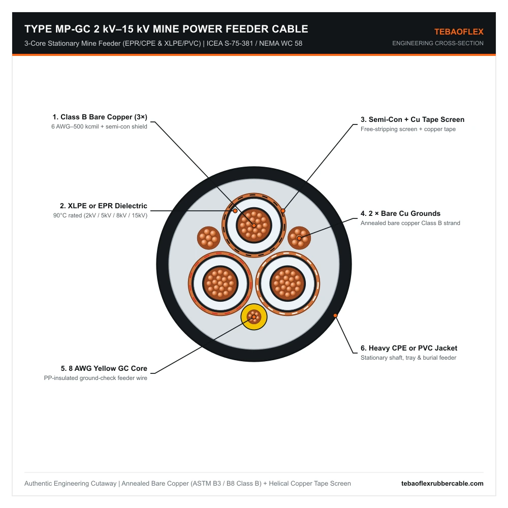
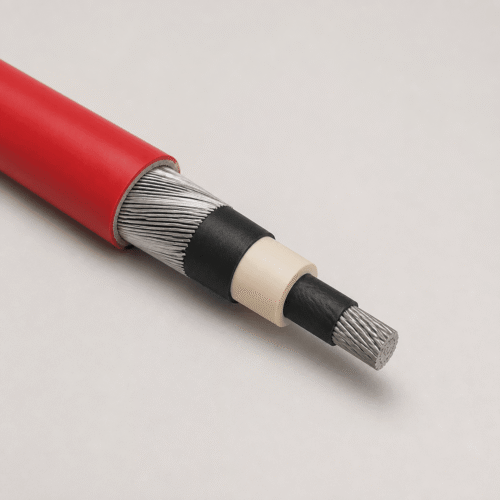
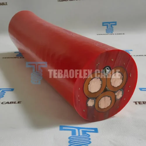
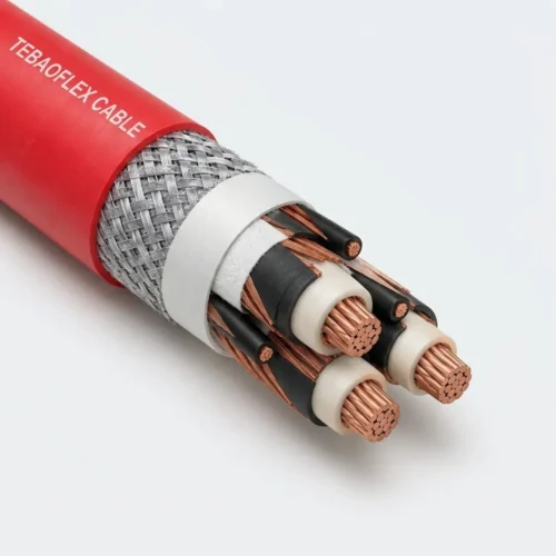
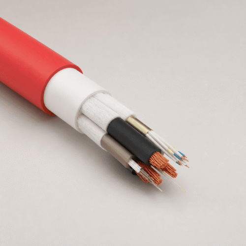
Type MP-GC feeder cutaway: 3 Class B bare copper phases, semi-con screens, XLPE/EPR dielectric, helically overlapped copper tape shields, 2 bare copper grounds, 8 AWG yellow GC, and CPE/PVC jacket.
Technical Characteristics
Electrical, dielectric wall, installation temperature, and regulatory parameters for Type MP-GC 2 kV–15 kV mine power feeders.
| Parameter | ICEA S-75-381 / NEMA WC 58 Rated Value |
|---|---|
| Rated Voltage Classes | 2,000 V | 5,000 V (100% 90 mil) | 8,000 V (100% 115 mil) | 15,000 V (100% 175 mil) |
| Insulation / Jacket Systems | Option A: 90°C EPR Insulation + Heavy Black CPE Jacket | Option B: 90°C XLPE Insulation + Heavy PVC Jacket |
| Conductor Temperature Rating | +90°C continuous normal operation | +130°C emergency overload | +250°C short circuit |
| Installation Operating Range | -40°C to +90°C (EPR/CPE) | -20°C to +90°C (XLPE/PVC fixed service) |
| Minimum Bending Radius | 12 × overall cable diameter (stationary horizontal, vertical, tray, duct, or direct burial) |
| Governing Standards | ICEA S-75-381 / NEMA WC 58; ASTM B3, B8 & B496; CAN/CSA-C22.2 No. 96; MSHA flame-resistant reference |
5 kV (90 mil), 8 kV (115 mil) & 15 kV (175 mil) Feeder Specifications
Complete dual-unit nominal dimensions, Class B stranding, grounding conductor sizes, weights, and +90°C ampacity ratings per ICEA S-75-381.
Table 1: Type MP-GC 3/C 5,000 V (100% Level, 90 mil Wall; Also Covers Heavy 90-mil 2kV/5kV EPR/CPE & XLPE/PVC)
| Power Cores | Area (mm²) | Class B Strands | Grounds (2 × AWG) | GC Core | Insul. / Jkt (in / mm) | Overall OD (in / mm) | Weight (lb/kft / kg/km) | Ampacity 40°C (A) |
|---|---|---|---|---|---|---|---|---|
| 3 × 6 AWG | 13.30 | 7 | 2 × 10 AWG | 8 AWG | 0.090 / 0.110 (2.3 / 2.8) | 1.30 / 33.0 | 1,060 / 1,577 | 93 |
| 3 × 4 AWG | 21.15 | 7 | 2 × 8 AWG | 8 AWG | 0.090 / 0.110 (2.3 / 2.8) | 1.41 / 35.8 | 1,441 / 2,144 | 122 |
| 3 × 2 AWG | 33.62 | 7 | 2 × 6 AWG | 8 AWG | 0.090 / 0.110 (2.3 / 2.8) | 1.47 / 37.3 | 1,827 / 2,718 | 159 |
| 3 × 1 AWG | 42.41 | 19 | 2 × 5 AWG | 8 AWG | 0.090 / 0.110 (2.3 / 2.8) | 1.54 / 39.1 | 2,168 / 3,226 | 184 |
| 3 × 1/0 AWG | 53.49 | 19 | 2 × 4 AWG | 8 AWG | 0.090 / 0.110 (2.3 / 2.8) | 1.63 / 41.4 | 2,602 / 3,871 | 211 |
| 3 × 2/0 AWG | 67.43 | 19 | 2 × 3 AWG | 8 AWG | 0.090 / 0.110 (2.3 / 2.8) | 1.72 / 43.7 | 3,010 / 4,478 | 243 |
| 3 × 3/0 AWG | 85.01 | 19 | 2 × 2 AWG | 8 AWG | 0.090 / 0.140 (2.3 / 3.6) | 1.89 / 48.0 | 3,265 / 4,859 | 279 |
| 3 × 4/0 AWG | 107.2 | 19 | 2 × 1 AWG | 8 AWG | 0.090 / 0.140 (2.3 / 3.6) | 2.01 / 51.1 | 4,190 / 6,234 | 321 |
| 3 × 250 kcmil | 126.7 | 37 | 2 × 1/0 | 8 AWG | 0.090 / 0.140 (2.3 / 3.6) | 2.10 / 53.3 | 4,825 / 7,179 | 355 |
| 3 × 350 kcmil | 177.3 | 37 | 2 × 2/0 | 8 AWG | 0.090 / 0.140 (2.3 / 3.6) | 2.31 / 58.7 | 6,062 / 9,019 | 435 |
| 3 × 500 kcmil | 253.4 | 37 | 2 × 4/0 | 8 AWG | 0.090 / 0.140 (2.3 / 3.6) | 2.59 / 65.8 | 8,427 / 12,538 | 536 |
Table 2: Type MP-GC 3/C 8,000 V (115 mil Wall) & 15,000 V (175 mil Wall) — ICEA S-75-381 MV Feeder Reference
| Power Cores | Grounds (2 × AWG) | 8 kV Insul./Jkt (mil) | 8 kV Nominal OD (in / mm) | 8 kV Weight (lb/kft / kg/km) | 15 kV Insul./Jkt (mil) | 15 kV Nominal OD (in / mm) | 15 kV Weight (lb/kft / kg/km) | Ampacity (8kV / 15kV) |
|---|---|---|---|---|---|---|---|---|
| 3 × 2 AWG | 2 × 6 AWG | 115 / 110 | 1.63 / 41.4 | 1,960 / 2,917 | 175 / 140 | 1.95 / 49.5 | 2,410 / 3,586 | 159 / 164 |
| 3 × 1 AWG | 2 × 5 AWG | 115 / 110 | 1.71 / 43.4 | 2,310 / 3,438 | 175 / 140 | 2.03 / 51.6 | 2,780 / 4,137 | 184 / 187 |
| 3 × 1/0 AWG | 2 × 4 AWG | 115 / 110 | 1.80 / 45.7 | 2,745 / 4,085 | 175 / 140 | 2.12 / 53.8 | 3,230 / 4,807 | 211 / 215 |
| 3 × 2/0 AWG | 2 × 3 AWG | 115 / 140 | 1.95 / 49.5 | 3,260 / 4,851 | 175 / 140 | 2.22 / 56.4 | 3,690 / 5,491 | 243 / 246 |
| 3 × 4/0 AWG | 2 × 1 AWG | 115 / 140 | 2.18 / 55.4 | 4,430 / 6,593 | 175 / 140 | 2.46 / 62.5 | 4,920 / 7,322 | 321 / 325 |
| 3 × 250 kcmil | 2 × 1/0 | 115 / 140 | 2.28 / 57.9 | 5,090 / 7,575 | 175 / 140 | 2.57 / 65.3 | 5,610 / 8,349 | 355 / 359 |
| 3 × 350 kcmil | 2 × 2/0 | 115 / 140 | 2.50 / 63.5 | 6,390 / 9,509 | 175 / 170 | 2.84 / 72.1 | 7,120 / 10,596 | 435 / 439 |
| 3 × 500 kcmil | 2 × 4/0 | 115 / 170 | 2.83 / 71.9 | 8,890 / 13,230 | 175 / 170 | 3.11 / 79.0 | 9,480 / 14,108 | 536 / 540 |
Stationary Mine Feeder vs. Portable Trailing Cable Matrix
Select Type MP-GC for fixed mine power backbones and Type W / G / SHD-GC for mobile face equipment.
| Mining Cable Model | Voltage Class, Ground / Shield Architecture & Primary Mining Duty |
|---|---|
| Type W Round 2kV (3C & 4C) | Round unshielded portable power cable (no bare ground wires) with 3 or 4 flexible tinned copper EPR cores inside a reinforced black or luminous CPE jacket. |
| Type W Flat 2kV (2C & 4C) | Low-profile parallel flat unshielded cable (2-core DC or 4-core AC, no bare grounds) engineered for tight multi-layer shuttle-car and roof-bolter reels. |
| Type G Flat 2kV (2C + Ground) | Parallel flat DC shuttle-car cable adding a centered stranded tinned copper equipment grounding conductor between the two 90°C EPR power cores. |
| Type G-GC Round 2kV (3C + 2G + GC) | Round unshielded 3-phase portable mining cable with 2 interstitial bare tinned copper grounds and 1 yellow PP ground-check pilot conductor. |
| Type MP-GC Feeder (2kV–15kV) | Stationary 3-core mine power feeder cable (Class B bare copper, copper-tape phase screens, 2 grounds + GC, EPR/CPE or XLPE/PVC) for shafts, boreholes, and trays. |
Frequently Asked Questions (FAQ)
Engineering FAQs on Type MP-GC vs. Type SHD-GC, EPR/CPE vs. XLPE/PVC, and vertical borehole support.
When should we specify EPR/CPE versus XLPE/PVC for Type MP-GC mine feeder cable?
Specify EPR/CPE when feeder runs are periodically relocated as longwall panels advance, pulled through wet undulating mine entries, or exposed to sub-zero -40°C surface portals. Specify XLPE/PVC for permanent stationary tray, conduit, tunnel wall-rack, or dry/wet duct installations seeking lower cable weight and tighter dielectric loss.
Why does Type MP-GC have a smaller outside diameter than Type SHD-GC of the same AWG and voltage?
Type MP-GC uses compact/concentric Class B stranding (19 or 37 strands) and thin overlapped copper tape shields rather than bulky rope-lay stranding (259–1,221 strands) and thick mold-cured drag jackets—reducing OD by 12–20% for easier conduit pulling and standard MV stress-cone termination.
Can Type MP-GC be installed vertically in mine shafts or boreholes?
Yes. Standard Type MP-GC is suitable for clamped vertical shaft runs supported at NEC / MSHA spacing intervals, and TEBAOFLEX can also apply galvanized steel wire armor (SWA) over the inner jacket for self-supporting deep borehole drops.
Request a Type MP-GC (2kV / 5kV / 8kV / 15kV) Feeder Quote
Specify system voltage (2 kV, 5 kV, 8 kV, or 15 kV), EPR/CPE or XLPE/PVC construction, conductor size (6 AWG to 500 kcmil), and reel lengths.
Explore All Mining & Tunneling Cables