Case Summary: A civil airport procurement inquiry in Russia requested 450 m of 400 Hz aircraft ground power cable (evaluated in 15 m and 28 m stand payout assemblies with buyer-fitted aircraft plugs) to connect apron pop-up PIT units to parked aircraft. Project cross-section records and sheath markings specify a symmetrical 4 × (1 × 70 + 4 × 1) mm² build combining tinned copper EPR power cores, 16 numbered FEP (F-46) pilot cores, and a high-visibility yellow PUR outer jacket.
1. Why Can an Airport PIT Inquiry Not Stop at “4×70 Aviation Cable With Signal Wires”?
Direct Answer: At 400 Hz AC (115/200 V aircraft ground power per ISO 6858:2017), inductive reactance (XL = 2πfL) reaches eight times its 50 Hz value and skin/proximity effects raise effective AC copper resistance. A generic 4 × 70 mm² mains cable lacks 28 V DC plug-interlock wires and can exceed allowable receptacle voltage drop across a single 15 m or 28 m PIT lead.
The Russian buyer initially requested technical details, meter pricing, production lead time, and delivery terms for 450 m of “4*70 aviation cable with signal wires” feeding parked civil aircraft from underground apron PIT boxes. Follow-up engineering review clarified two operational constraints that govern quotation accuracy: candidate stand cut lengths of 15 m and 28 m, and local field termination of the 400 Hz aircraft nose-gear plugs by the customer’s technicians.
In a three-phase four-wire 115/200 V 400 Hz ground support circuit, line-to-line voltage drop across an individual stand cable of length L (km) carrying load current I (A) at power factor cos φ follows ΔULL = √3 × I × L × (R400Hz cos φ + X400Hz sin φ). Because reactive impedance dominates at 400 Hz, conductor lay geometry and converter sense-wire compensation must be evaluated per stand run rather than against the 450 m aggregate order quantity. For underlying impedance formulas, see our cable AC resistance, reactance, and impedance calculation guide and our 400 Hz aircraft ground power cable selection guide.
| Stand Lead Scenario (90 kVA / 260 A, cos φ = 0.8) | Representative 400 Hz RAC / XL (Ω/km) | Calculated Drop at 15 m | Calculated Drop at 28 m | Apron Stand Engineering Implication |
|---|---|---|---|---|
| Conventional 50 Hz 4 × 70 mm² Power Cable (Unsuitable Baseline) | R400Hz ≈ 0.36 Ω/km X400Hz ≈ 0.64 Ω/km | 4.58 V L-L (2.29% of 200 V) | 8.55 V L-L (4.28% of 200 V) | High 400 Hz reactance consumes regulator margin and omits 28 V DC E/F safety interlock & voltage-sense cores |
| Quad Composite 4 × (1 × 70 + 4 × 1) mm² PIT Build (Case Topology) | R400Hz ≈ 0.35 Ω/km X400Hz ≈ 0.46 Ω/km | 3.75 V L-L (1.88% of 200 V) | 7.00 V L-L (3.50% of 200 V) | Balanced quad lay fits compact PIT coils; 16 numbered 1 mm² FEP cores support 28 V DC interlocks and converter line-drop sensing |
| Phase-Split 7-Core Low-Reactance 400 Hz Build (6 × 35 + 1 × 70 + Pilot) | R400Hz ≈ 0.33 Ω/km X400Hz ≈ 0.24 Ω/km | 2.74 V L-L (1.37% of 200 V) | 5.12 V L-L (2.56% of 200 V) | Diametrically split phases cancel magnetic flux, cutting reactive drop by ~45% for longer 28 m to 60 m bridge or reel runs |
Engineering calculation boundary: benchmark figures vs. contract test sheet
The impedance values above illustrate standard three-phase 400 Hz physics at 90 kVA (260 A at 200 V L-L, cos φ = 0.8) so integrators can compare 15 m versus 28 m stand leads before ordering. Exact 400 Hz resistance, reactance, and converter line-drop compensation range must be verified on the approved order datasheet using our three-phase cable voltage drop calculation method.
2. What Does the 4 × (1 × 70 + 4 × 1) mm² Composite Core Schedule Mean?
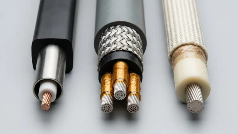
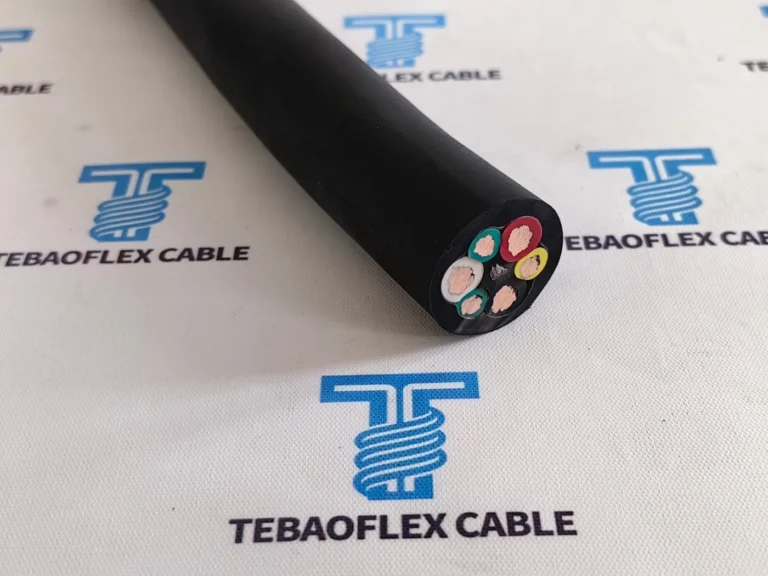
Direct Answer: The sheath legend 4 × (1 × 70 + 4 × 1) mm² defines four identical composite sub-assemblies laid up symmetrically inside one yellow PUR outer jacket. Each sub-assembly pairs one 70 mm² Class 5 tinned copper EPR power core with four 1 mm² Class 6 tinned copper grey white-numbered FEP (F-46) control cores, providing four 70 mm² power paths and 16 pilot/sense wires.
Writing the core schedule as 4 × (1 × 70 + 4 × 1) mm² rather than “4 × 70 + 16 × 1” captures the internal sub-unit layout recorded in the project cross-section summary. Grouping four 1 mm² fluoropolymer control wires with each 70 mm² power conductor preserves cross-sectional roundness when the cable bends over PIT hatch rollers and enters the rear compression gland of a 400 Hz aircraft plug.
Within those 16 numbered 1 mm² cores, airport ground power integrators typically assign active conductors to the 28 V DC E/F plug-insertion interlock loop, converter remote voltage-sensing leads at the aircraft pin tip, and PIT hatch or ground-power-available status lamps, leaving remaining numbered wires as field-serviceable spares in case a pilot wire is damaged during plug maintenance.
4 × (1 × 70 + 4 × 1) mm² build (illustrative layout; refer to approved contract drawing for dimensional tolerances and core numbering).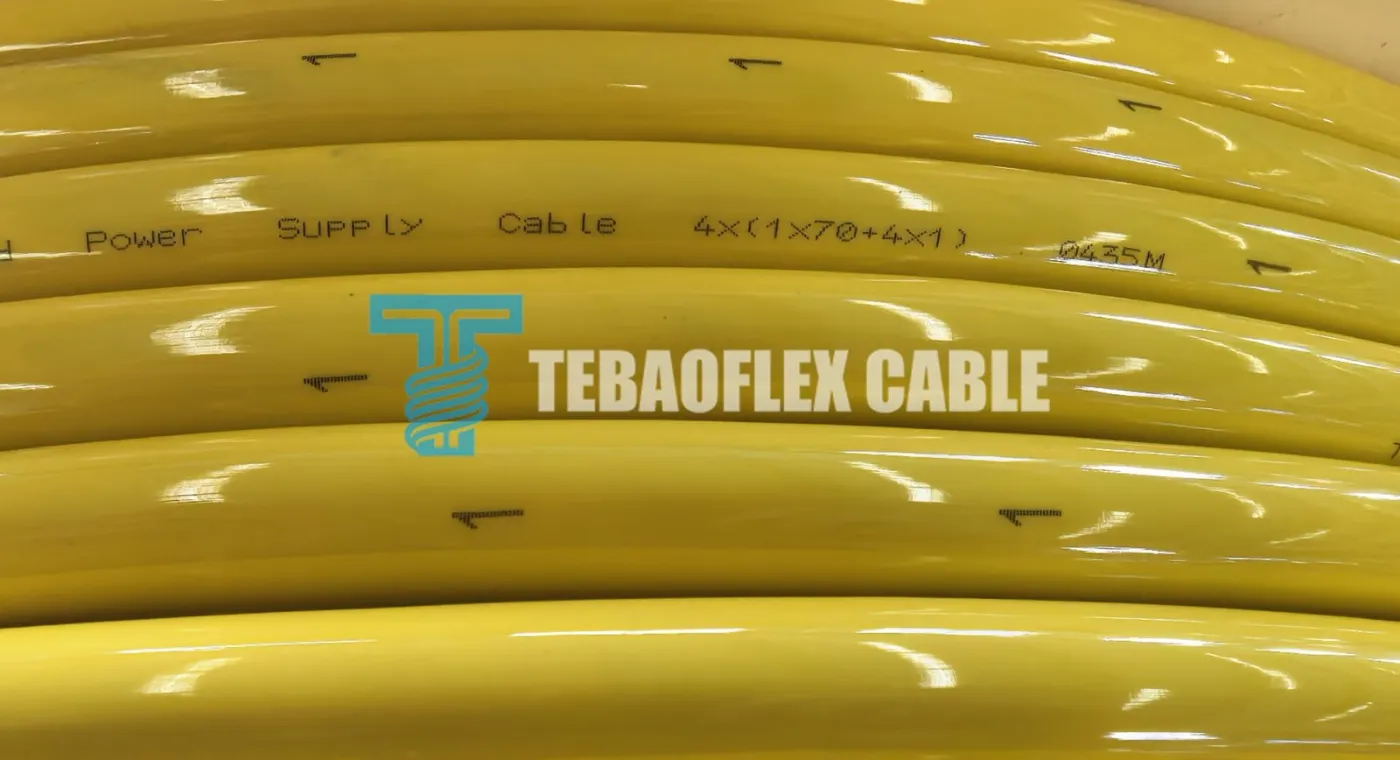
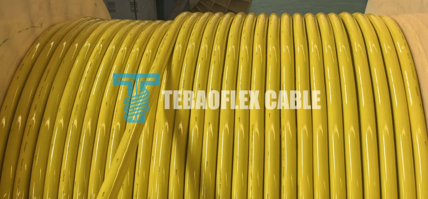
Power Supply Cable 4x(1x70+4x1) 0435M with sequential meter counter on the yellow PUR jacket.| Physical Cable Layer | Documented Russia PIT Project Specification | Engineering Function & Pre-Order Verification Point |
|---|---|---|
| Main power conductors | 4 × 70 mm² tinned fine-stranded copper (IEC 60228:2023 Class 5) | Tin plating prevents copper sulfide/oxide corrosion in damp PIT vaults; confirm phase vs. neutral lug barrel ID |
| Power core insulation | Cross-linked ethylene propylene rubber (EPR), black | 90 °C continuous thermal rating and elastomeric flexibility; confirm phase identification sleeves at plug ends |
| Integrated control cores | 16 × 1 mm² total (4 × 1 mm² per power sub-assembly), IEC 60228 Class 6 extra-flexible tinned copper | Extra-fine Class 6 stranding resists flex-fatigue breakage behind heavy hand-maneuvered aircraft nose plugs |
| Control core insulation | Fluorinated ethylene propylene FEP (F-46), grey with white numbers | Thin-wall fluoropolymer withstands soldering/heat-shrink assembly up to 200 °C without insulation melt-back |
| Outer protective sheath | High-visibility aviation yellow polyurethane (PUR) | High cut, concrete-drag, Jet A-1 kerosene, and de-icer resistance; lock cold-bend temperature grade on contract |
3. How Does This PIT Cable Compare With Other Airport Ground Support Cables?
Direct Answer: Airport stands deploy distinct cable geometries for 400 Hz AC pop-up pits, motorized passenger boarding bridge reels, 28 V DC turbine start carts, and 6.6 A airfield lighting loops. Selecting between quad composite, seven-core phase-split, and concentric DC builds depends on supply frequency, run length, reeling tension, and plug pinout.
Procurement teams specifying ground support equipment across multiple terminal gates often combine stationary PIT payout leads with motorized drum-reeling cables and apron primary feeders. Reviewing our 400 Hz airport ground power cable product specifications alongside broader specialty aviation and fluoropolymer-insulated cables ensures each stand subsystem matches its electrical and mechanical duty cycle.
| Airport Subsystem & Cable Type | Typical Core Geometry | System Supply & Frequency | Primary Mechanical Duty & Stand Deployment |
|---|---|---|---|
| Quad Composite 400 Hz PIT Cable (This Russia Case Build) | 4 × (1 × 70 + 4 × 1) mm²EPR power + 16 FEP pilot + yellow PUR | 115/200 V AC, 400 Hz (ISO 6858 interface) | Short-to-medium (15 m to 28 m) underground apron PIT storage coils and manual stand payout with 16 numbered control wires |
| Phase-Split 7-Core 400 Hz GPU & Bridge Cable | 6 × 25-50 + 1 × 50-95 mm² + control bundle + optional aramid braid | 115/200 V AC, 400 Hz (90 kVA to 180 kVA) | Motorized or spring-driven boarding-bridge cable reels and mobile diesel/solid-state GPU leads up to 60 m requiring minimal XL |
| 28V DC Single-Core Aircraft Ground Power Cable | 1 × (120 + 4 × 1.0) mm² or twin-lead DC power + interlock | 28.5 V DC continuous / high peak start current | Regional turboprops, business jets, and helicopters using 28 V DC mobile GPU carts and nose-receptacle interlock plugs |
| RG7H1R 3.6/6 kV Airfield Lighting Primary Cable | 1 × 6 mm² screened HEPR insulation + polychloroprene/PVC sheath | 6.6 A constant-current series loop (up to 3.6/6 kV) | Fixed underground conduit distribution feeding apron edge lights, taxiway guidance signs, and stand isolation transformers |
4. What Do the Factory Drum and Crating Photographs Verify Before Cutting Stand Leads?
Direct Answer: The factory dispatch photographs verify moisture-barrier film wrapping over wooden export drums and full timber lagging battens strapped with tensioned steel bands. Before cutting 15 m or 28 m stand assemblies from a 450 m multi-drum shipment, receiving engineers should reconcile start/end meter marks against drum net lengths.
Overland freight into Russia exposes heavy cable reels to crane hooks, forklift blades, road salt, and warehouse humidity swings. Wrapping the yellow PUR windings in sealed polyethylene film before nailing full-circumference wooden lagging battens prevents cosmetic scuffing or notch damage that could later initiate cold-weather sheath splitting on the apron.
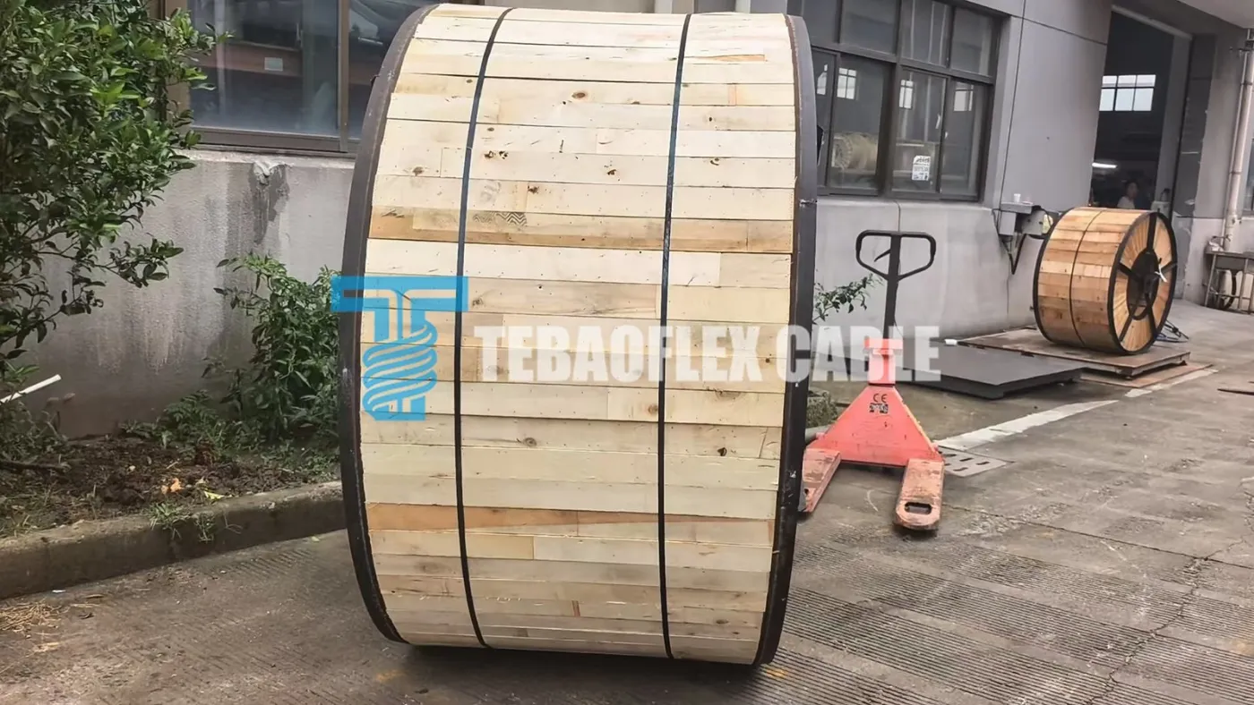
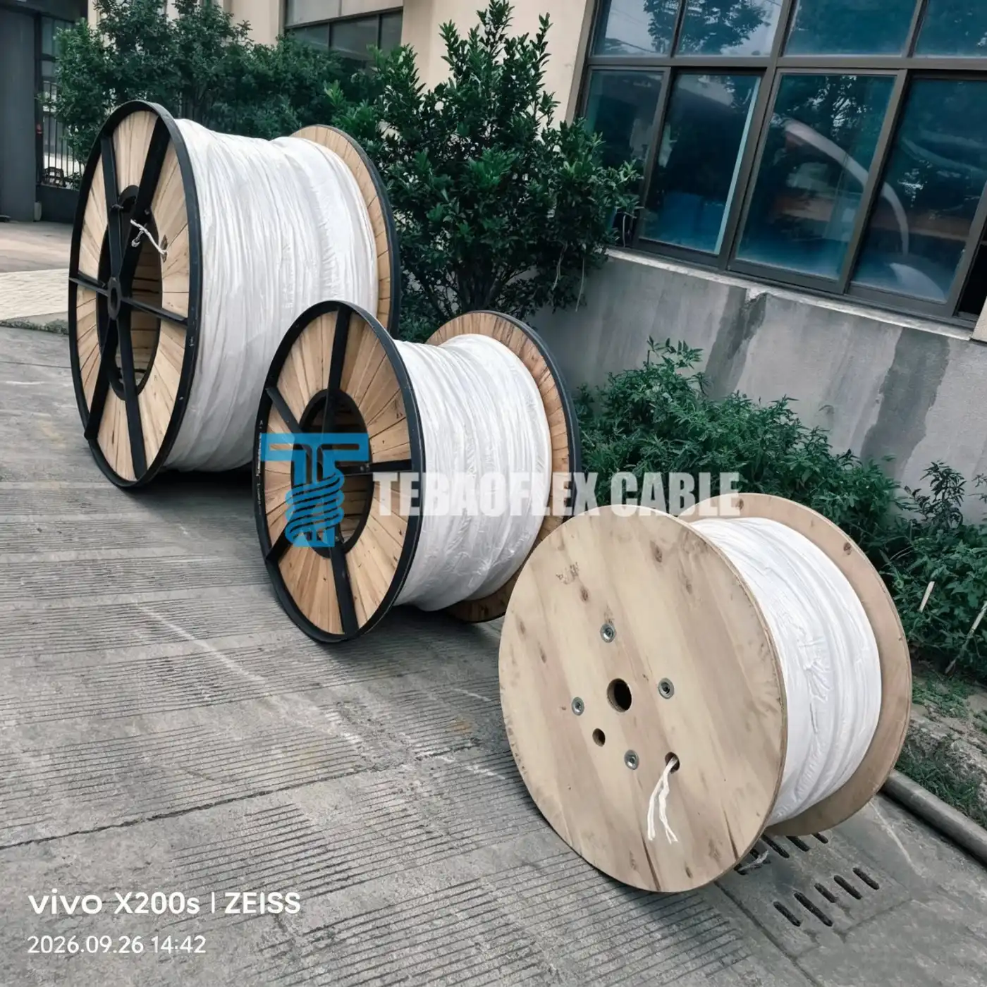
- Inspect timber lagging and flange integrity on arrival: Check steel strapping and wooden battens for transit impact before uncrating, ensuring drum flanges have not shifted inward against the outer yellow PUR layer.
- Reconcile sequential meter marks per drum: Read both inner-end and outer-end printed meter legends (illustrated by
0435Mon the sheath close-up) to map exact cut plans for15 mand28 mPIT leads without creating unusable short offcuts. - Measure finished outer diameter against aircraft plug glands: Confirm actual cable OD with calipers at three points before stripping so rear strain-relief grommets compress evenly for watertight apron sealing.
- Verify DC resistance and insulation resistance before cutting: Run baseline continuity and megohmmeter checks on all four
70 mm²power cores and all 16 numbered1 mm²FEPcontrol wires against the factory routine test sheet. - Map and label the 16 white-numbered FEP cores to plug pins: Cross-check active
28 V DCE/F interlock wires, sense leads, and capped spare cores on a bench harness chart before crimping phase lugs or potting the aircraft connector.
5. Which Winter Apron and Plug Interface Checks Must Be Signed Off Before Commissioning?
Direct Answer: Because the Russian buyer planned independent aircraft plug termination, cold-flex temperature limits (-40 °C standard polyether PUR vs. -50 °C arctic formulations), chemical resistance to potassium-formate de-icers and Jet A-1 fuel, PIT roller bending radius, and plug gland clamping range must be locked on the contract datasheet.
Project correspondence specifically raised sub-zero winter flexibility and thermal endurance questions. A generic “yellow PUR” label on an inquiry sheet does not by itself certify cold-impact survival on frozen Russian concrete aprons or compatibility with motorized versus manual PIT retrieval rollers. Signing off the six interface parameters below converts a preliminary cable inquiry into an auditable aviation procurement specification.
| Interface Sign-Off Item | Required Buyer / Airport Integrator Input | Engineering Risk Prevented Before Plug Assembly |
|---|---|---|
| 400 Hz converter & load rating | Converter kVA rating (e.g., 90 kVA), nominal 115/200 V AC output, and remote sense compensation window | Prevents under-voltage trips at the aircraft receptacle on 28 m stand leads under peak cabin-cooling load |
| Approved stand cut schedule | Exact piece counts and cut lengths (how many 15 m vs. 28 m assemblies + PIT vault slack allowance) | Eliminates short drum remnants and ensures full reach to wide-body and narrow-body nose-gear receptacles |
| 16-core FEP pinout schematic | Wiring table assigning white-numbered 1 mm² FEP cores to 28 V DC E/F interlock, sense, indicator, and spare pins | Prevents reversed sense polarity or open interlock loops during field plug termination |
| Aircraft plug & lug tolerances | 400 Hz plug model, rear cable-clamp ID window, and crimp barrel ID for Class 5 tinned 70 mm² copper | Guarantees full mechanical pull-out retention and IP67 moisture sealing at the connector neck |
| Winter cold-bend & PIT mechanics | Minimum ambient payout temperature (-40 °C or -50 °C), PIT hatch roller radius, and daily bend cycles | Specifies the exact low-temperature polyether PUR compound and minimum dynamic bending radius |
| Inspection & customs documentation | Required IEC routine test reports (conductor resistance, spark/HV test) and destination EAC/GOST paperwork | Aligns factory quality release records with civil airport electrical acceptance before dispatch |
6. Frequently Asked Questions
Can a standard 4 × 70 mm² 50/60 Hz power cable replace a 4 × (1 × 70 + 4 × 1) mm² 400 Hz airport PIT cable?
No. A conventional 50/60 Hz 4 × 70 mm² power cable lacks the 16 integrated 1 mm² FEP control cores needed for 28 V DC aircraft plug E/F safety interlocks and remote voltage sensing, develops roughly eight times higher inductive reactance at 400 Hz, and lacks a cold-flexible aviation PUR outer sheath resistant to Jet A-1 kerosene, hydraulic fluid, and runway de-icers.
What does the sheath marking 4 × (1 × 70 + 4 × 1) mm² mean on this aircraft ground power cable?
The notation defines four symmetrical composite sub-assemblies laid up inside one yellow PUR jacket. Each sub-assembly combines one 70 mm² IEC 60228 Class 5 tinned copper EPR-insulated power core with four 1 mm² IEC 60228 Class 6 tinned copper grey white-numbered FEP (F-46) control cores, providing four 70 mm² power paths and 16 pilot or sense cores in total.
Why are FEP (F-46) insulation and Class 6 stranding specified for the 1 mm² control cores?
Pilot wires inside an aircraft ground power cable experience repeated sharp bending right behind the heavy nose-gear receptacle plug. IEC 60228 Class 6 extra-fine tinned copper strands resist flex-fatigue wire breakage, while thin-wall FEP fluoropolymer insulation withstands soldering or heat-shrink assembly temperatures up to 200 °C without shrinking back and keeps overall cable diameter compact.
Why must 400 Hz voltage drop be calculated on 15 m and 28 m stand assemblies rather than the 450 m order total?
450 m was the Russian buyer’s aggregate procurement quantity across multiple apron stands, whereas each parked aircraft receives power through one individual 15 m or 28 m PIT-to-aircraft lead. Terminal voltage regulation under ISO 6858:2017 (115/200 V AC at 400 Hz) depends on the per-kilometer 400 Hz resistance and reactance multiplied by the single stand lead length and peak load current.
What do the Russia PIT project photographs verify, and what still requires contract sign-off?
The factory photographs document the high-visibility yellow PUR cable on wooden reels, the sequential inkjet legend Power Supply Cable 4x(1x70+4x1) 0435M, moisture-barrier film wrapping, and steel-strapped timber lagging crates. Final cold-bend temperature limits (-40 °C vs. -50 °C), measured 400 Hz impedance test values, exact cut-length schedules, and stand commissioning records remain governed by the signed order datasheet and inspection pack.
Specifying 400 Hz PIT, Mobile GPU, or Boarding-Bridge Ground Power Cables?
Send our engineering team your converter kVA rating, required power and numbered FEP pilot core schedule, individual stand cable lengths (such as 15 m, 28 m, or custom reel runs), aircraft plug model, and minimum winter operating temperature for a pre-quotation voltage-drop and OD gland-fit review.
Source & engineering verification note: Compiled from the Russia civil airport PIT 400 Hz inquiry correspondence, project cross-section summary, sheath-marked cable photographs, and factory export-crating records. Conductor stranding classes reference IEC 60228:2023 and aircraft electrical supply interface context references ISO 6858:2017. Grade-specific winter cold-bend limits, routine 400 Hz impedance test figures, final cut-length schedules, and airport stand commissioning records remain governed by signed purchase documentation. Reviewed by the TEBAOFLEX Engineering Team, October 2026.