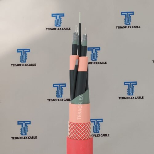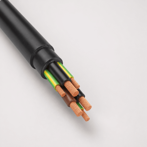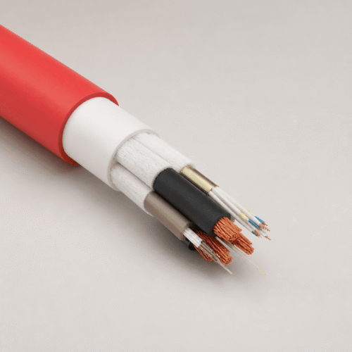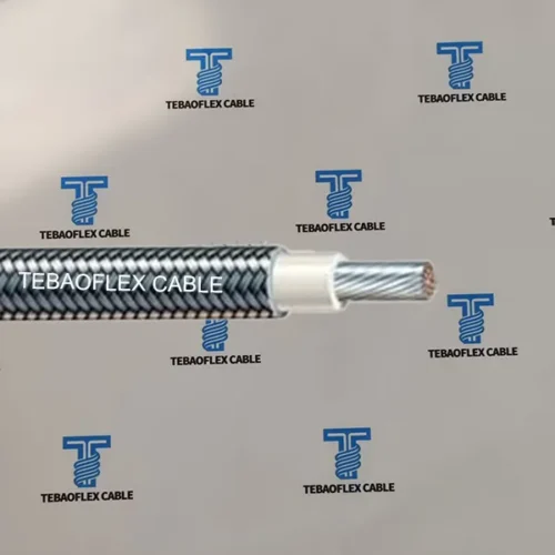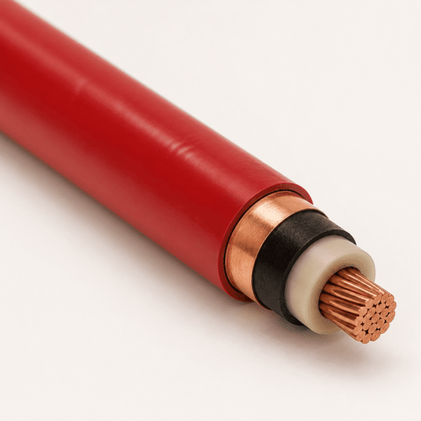
TEBAOFLEX RG7H1R 3.6/6 kV is a single-core, radial-field screened medium-voltage airport lighting primary cable engineered for 6.6 A and 20 A constant-current series circuits connecting airfield lighting vaults (constant-current regulators, CCRs) to runway, taxiway, and approach-light isolating transformers. Combining compact Class 2 bare copper, G7 high-modulus HEPR rubber insulation, inner and outer extruded semi-conducting screens, a bare copper tape shield, and an aviation-red PVC outer jacket, it prevents partial discharge in flooded underground airfield ducts while providing unmistakable circuit identification.
1. Application Scope & International Airfield Standard Crosswalk
Airfield ground-lighting (AGL) primary loops operate as constant-current series rings up to 5 kV peak operating voltage across multi-kilometer underground duct banks, handholes, and transformer pits:
- CAT I / CAT II / CAT III Runway & Taxiway Loops: Primary series interconnection from substation CCR cabinets to encapsulated AGL isolating transformers along runway edges, centerlines, touch-down zones, and rapid-exit taxiways.
- Approach, PAPI & Stop-Bar Circuits: High-reliability
10 mm²and16 mm²low-loss feeder runs minimizing regulator kVA loading over long vault-to-threshold distances. - Duct Bank, Trench & Pit Routing: Moisture-, de-icing-salt-, and jet-fuel-splash-resistant red PVC jacket suited to buried HDPE/PVC conduits and concrete transformer chambers.
| AGL Primary Cable Standard | Voltage Class | Insulation / Screen | Typical Regional Specification |
|---|---|---|---|
| RG7H1R — This Page | 3.6/6 kV (Um 7.2 kV) | G7 HEPR + Semi-Con + Cu Tape / Red PVC | European / CEI 20-13 / ENV 50213 / ICAO projects (6–25 mm²) |
| FL2XCY / FLG2XCY AGL | 3.6/6 kV or 5 kV | XLPE + Concentric Cu Wire/Tape / PVC or PE | DIN VDE / CENELEC European airport specifications (6 mm²) |
| FAA L-824 Type B / Type C | 5 kV | EPR (Type B) or XLPE (Type C), Shielded/Unshielded | FAA AC 150/5345-7 projects (8 AWG / 8.37 mm²) |
Field-Assembled Primary Connector Compatibility Check: Primary AGL series loops terminate onto isolating-transformer leads using plug-and-receptacle kits (such as metric L-823 screened connector kits). Always confirm your connector sleeve’s accepted insulation diameter and overall jacket diameter window against the table in Section 4 before release to production.
2. Cable Construction (Authentic RG7H1R 6-Layer Screened Design)
Under Italian CEI / European standard nomenclature, every character in RG7H1R defines a verified physical layer:
+90°C continuous and +250°C short-circuit.0.075 mm tape thickness) providing fault/leakage current return and lightning surge screening.3. Technical Characteristics
Electrical, thermal, and mechanical installation ratings for TEBAOFLEX RG7H1R 3.6/6 kV are summarized below:
| Parameter | Engineering Specification |
|---|---|
| Rated Voltage U0/U (Um) | 3.6/6 kV (Max three-phase/system voltage 7.2 kV AC) |
| Routine AC Dielectric Test | 11 kV AC (50 Hz, 5 min) + partial-discharge screening verification |
| Nominal AGL Loop Current | 6.6 A or 20 A constant-current series circuits (plus 3.6/6 kV feeder duty) |
| Fixed Operating Temperature | -50°C to +90°C (minimum laying temperature -5°C) |
| Max. Conductor Temperature | +90°C continuous operation; +250°C short-circuit (max 5 s) |
| Minimum Bending Radius | 15 × overall cable diameter (OD) during pulling and pit dressing |
| Max. Pulling Tension (Ducts) | 50 N/mm² of copper cross-section (500 N for 1×10 mm² using pulling stocking/eye) |
| Standards & Reaction to Fire | CEI 20-13 / CEI UNEL 35756 / ENV 50213 / EN 50575 / IEC 60332-1-2 |
4. Dimensional & Electrical Specification Table (1×6 to 1×25 mm²)
The documented 1 × 10 mm² airfield primary construction and companion 6 mm², 16 mm², and 25 mm² feeder sizes are detailed below:
| SKU | Conductor Size | Max DC Res. 20°C (Ω/km) | Nom. Insulation Wall (mm) | Min. Cu Tape Shield (mm) | Nom. Sheath Wall (mm) | Nom. Overall OD (mm) | Approx. Weight (kg/km) |
|---|---|---|---|---|---|---|---|
RG7H1R-1X6 | 1 × 6 mm² | 3.08 | 2.3 | 0.075 | 1.4 | 12.8 | 245 |
RG7H1R-1X10 | 1 × 10 mm² (Standard Listed) | 1.83 | 2.3 | 0.075 | 1.4 | 14.0 | 305 |
RG7H1R-1X16 | 1 × 16 mm² | 1.15 | 2.5 | 0.075 | 1.4 | 15.6 | 395 |
RG7H1R-1X25 | 1 × 25 mm² | 0.727 | 2.5 | 0.075 | 1.5 | 17.4 | 520 |
Looking for armoured 3.6/6 kV industrial feeders or specialty high-temperature wiring? Compare our (N)3GHSSYCY 3.6/6 kV steel-wire-armoured cable, high-temperature & specialty cables, and industrial & control cables.
5. Frequently Asked Engineering Questions
What do the letters and numbers in RG7H1R stand for?
Under Italian CEI / European cable nomenclature, R denotes a compact stranded copper conductor, G7 denotes high-modulus ethylene-propylene rubber (HEPR) insulation rated to +90°C continuous (+250°C short-circuit), H1 denotes extruded semi-conducting screens combined with a bare copper tape metallic screen, and the final R denotes an abrasion- and moisture-resistant PVC outer sheath (supplied in aviation-red for airfield primary circuits).
Why is a 3.6/6 kV screened cable required for 6.6 A airport lighting series loops?
Airfield ground-lighting (AGL) runways and taxiways use long constant-current series loops (typically 6.6 A) powered by up to 30 kVA constant-current regulators (CCRs), generating loop output voltages up to 4.5–5 kV. Extruded semi-conducting layers plus the 0.075 mm bare copper tape screen radialize the electric field, suppress partial discharge in damp underground ducts, protect personnel during maintenance, and divert lightning-induced surges safely to earth.
When is 1 × 10 mm² selected instead of 1 × 6 mm² on AGL primary circuits?
While 1 × 6 mm² (3.08 Ω/km at 20°C) handles standard-length 6.6 A runway edge and taxiway loops, airport designers specify 1 × 10 mm² (1.83 Ω/km at 20°C) or 1 × 16 mm² on extended 8–15 km CAT II/III runway, approach-light, or remote vault-to-threshold feeder runs to lower I²R regulator losses and keep total loop load within the CCR kVA rating.
How does RG7H1R 3.6/6 kV compare with FAA L-824 Type C 5 kV airfield cable?
European/ICAO tenders commonly specify metric screened 3.6/6 kV cables such as RG7H1R (6 mm² or 10 mm², G7 HEPR + semi-con + Cu tape + red PVC) per CEI 20-13 / ENV 50213, whereas North American FAA AC 150/5345-7 projects specify 8 AWG (8.37 mm²) 5 kV L-824 Type C XLPE or EPR cables. Confirm whether your airport consultant specifies metric connector kits for 6 mm² or 10 mm² screened cable.
What minimum bending radius and installation precautions apply to RG7H1R?
Observe a minimum bending radius of 15 × overall cable diameter (210 mm for 1 × 10 mm² at 14.0 mm OD) during duct pulling and transformer pit routing so the 0.075 mm copper tape shield and semi-conducting interfaces are never creased. Continuously bond and earth the copper tape shield in accordance with the airport AGL earthing scheme.
What information should be included in an airport lighting cable RFQ?
Provide the conductor cross-section (6, 10, 16, or 25 mm²), voltage rating (3.6/6 kV), governing standard (CEI / ENV 50213 / EN 50575 / ICAO), plug-connector compatibility OD window if factory-moulded or field-assembled kits are used, drum lengths, total meterage, and destination airport/port.
Request a Factory Quote for RG7H1R 3.6/6 kV Airport Lighting Primary Cable
Send your conductor cross-section (6 mm² or 10 mm²), total drum meterage, primary connector kit dimensions, and airport tender specification. Our medium-voltage team will provide a datasheet and quotation within 24 hours.