VFD motor cable length is not only a voltage-drop question. A variable-frequency drive sends fast pulse-width-modulated voltage edges into the motor cable. As the cable becomes electrically longer, propagation delay, cable capacitance and impedance mismatch can increase motor-terminal voltage stress, common-mode current and electromagnetic interference. The cable may pass ampacity and steady-state voltage-drop checks while the drive–cable–motor system still needs an output reactor, dV/dt filter, sine-wave filter or a different installation arrangement.
There is no universal “maximum VFD cable length.” The permitted distance depends on the exact drive and power rating, pulse rise time, motor insulation, cable construction, grounding, switching settings, output filter and whether one or several motors are connected. This guide gives engineers and procurement teams a practical way to evaluate those factors without turning a manufacturer-specific limit into a general rule.
| Length-related effect | What changes as the run grows | What to verify |
|---|---|---|
| Steady-state voltage drop | Total conductor resistance and reactance increase | Running and starting voltage at the motor |
| Reflected-wave stress | Longer propagation delay can allow reflected pulses to add at the motor | Drive cable-length table, motor insulation and output treatment |
| Cable capacitance | Total phase-to-phase and phase-to-screen capacitance increases | Drive output-current capability and nuisance-trip limits |
| EMC and common mode | More cable can provide more coupling area and high-frequency return paths | Screen, PE, bonding, routing and 360° termination |
| Mechanical duty | Long routes can add cable weight, pulling force and motion demands | Fixed, drag-chain, festoon or reeling construction |
Why VFD Cable Length Matters More Than Ordinary Motor-Feeder Length
A motor connected directly to a sinusoidal supply is normally evaluated using power-frequency current, voltage drop, starting performance, short-circuit withstand and installation conditions. A VFD system needs those conventional checks too, but its output is a train of switched pulses rather than a smooth sine wave. The motor current can be close to sinusoidal while the voltage at the drive terminals changes very rapidly.
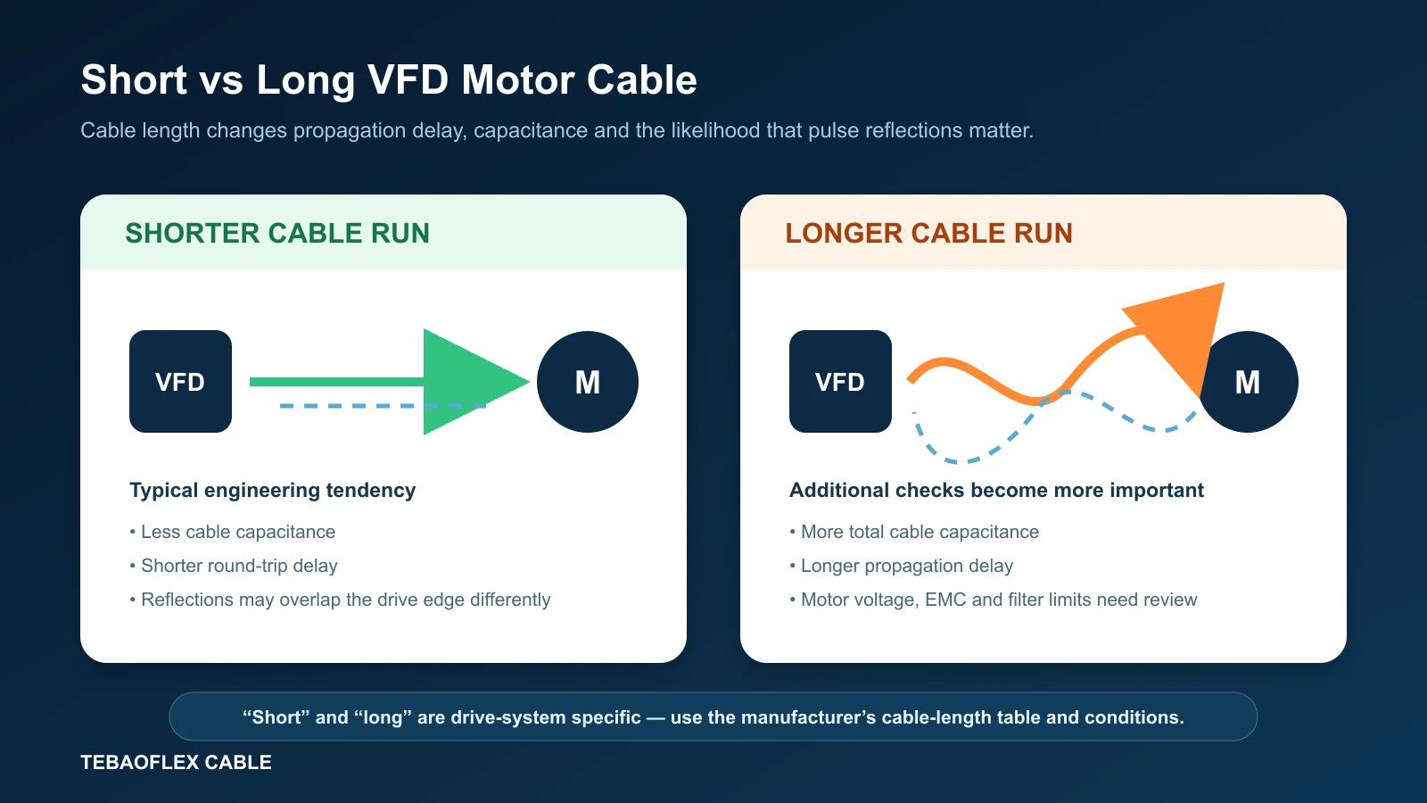
Each voltage edge travels through the motor cable at a finite propagation velocity. The cable behaves as a distributed network of inductance and capacitance. When the travelling wave reaches the motor, the difference between the cable’s characteristic impedance and the motor’s high-frequency input or surge impedance can cause part of the wave to reflect. The returning wave can interact with subsequent drive pulses. This is why the electrical meaning of “long cable” depends on pulse timing and not only on metres.
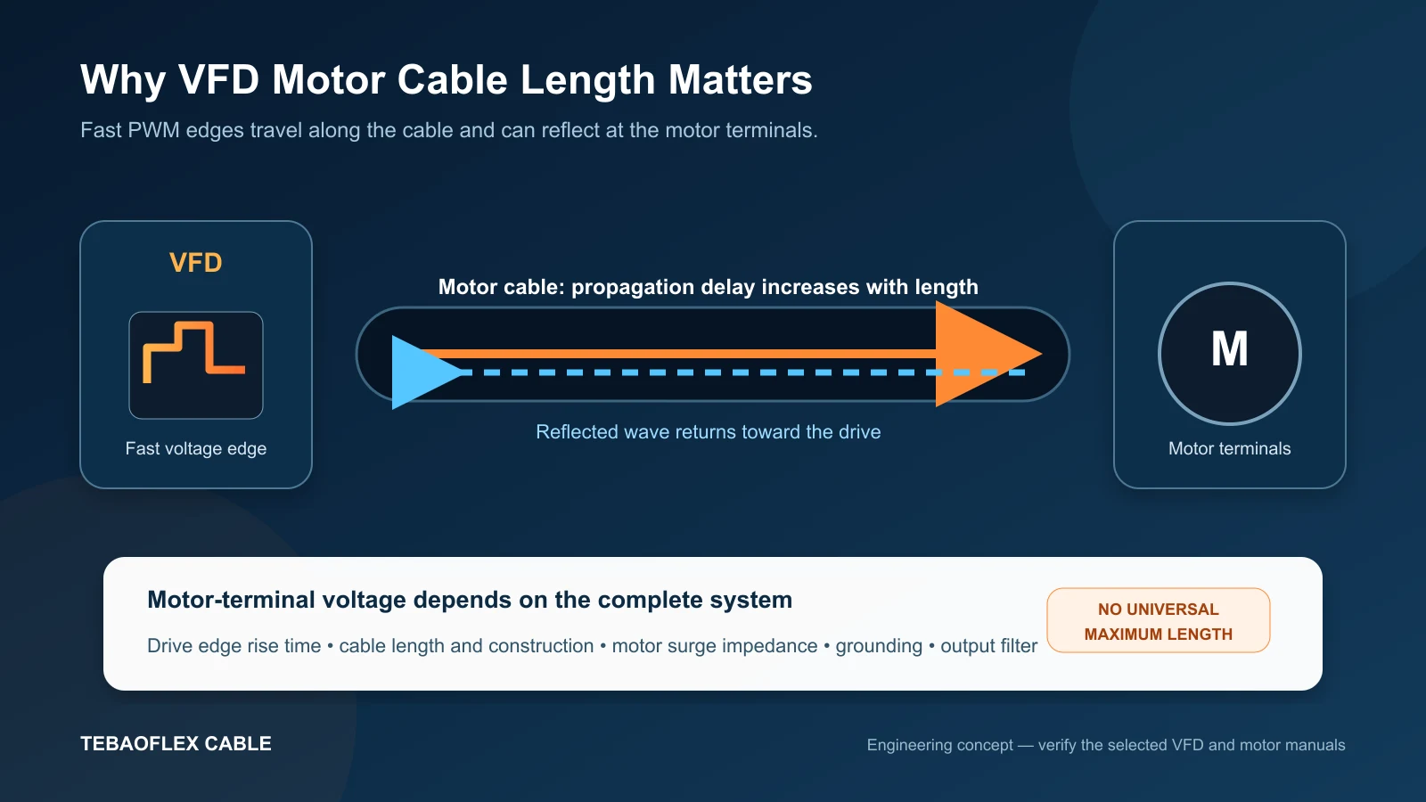
ABB’s Technical Note 176 on motor-cable distance identifies cable length and size, motor impedance and the drive IGBT rise time among the factors that influence reflected-wave behaviour. The note also explains that filtering, carrier frequency, grounding and single- or multiple-motor arrangements may change the acceptable installation. These are system variables, not a universal cable-only limit.
What Is dV/dt at a VFD Motor?
dV/dt is the rate at which voltage changes with time. A steep VFD output edge has a large voltage change over a short rise time. At the motor terminals, reflected waves can increase the peak voltage and the apparent edge stress applied to turn-to-turn and phase insulation. The severity depends on both the incident pulse and the network through which it travels.
Switching frequency and pulse rise time are related to drive operation but are not interchangeable. Switching frequency describes how often the power semiconductors switch in a modulation pattern. Rise time describes how quickly an individual voltage transition occurs. Reflected-wave critical length is more directly linked to edge rise time and round-trip propagation delay. A cable-length rule based only on carrier frequency therefore misses an important variable.
How Reflected Waves Create Motor-Terminal Overvoltage
A fast edge launched by the drive sees the cable’s characteristic impedance. At the motor, the high-frequency impedance is normally different, so the incident voltage is not absorbed without reflection. Under some combinations of rise time, cable length, motor and drive, the incident and reflected components can add and create a motor-terminal peak higher than the drive DC-link step would suggest.
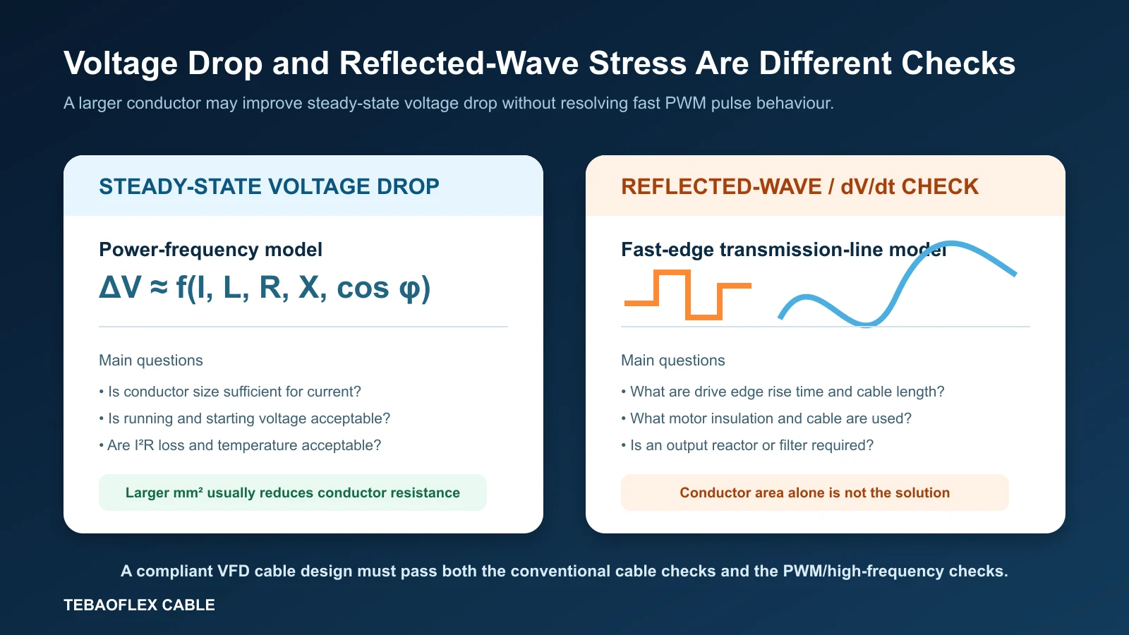
That process is different from the gradual voltage loss caused by conductor resistance. Reflected-wave stress can occur even when the measured fundamental-frequency voltage drop is acceptable. Conversely, a long cable can have an unacceptable voltage drop even if the selected drive, motor and filter keep high-frequency terminal stress within their permitted limits.
Is There a Critical VFD Motor Cable Length?
Engineers sometimes define a critical length by comparing the cable’s wave travel time with the drive pulse rise time. That is a useful concept, but it should not be converted into one site-wide number. Propagation velocity varies by cable construction, rise time varies by drive design and operating conditions, and motor surge impedance changes with motor size and winding construction.
The practical answer is to open the hardware or system manual for the exact drive family and frame size. Look for separate limits for shielded and unshielded cable, output reactors, dV/dt filters, sine filters, switching frequency, EMC category and multi-motor operation. ABB’s ACQ80-04 hardware manual, for example, treats motor cable and output-filter limits as product- and configuration-specific. Its tables should be used for the relevant ABB equipment, not copied as a generic industry threshold.
VFD Cable Voltage Drop vs Reflected-Wave Stress
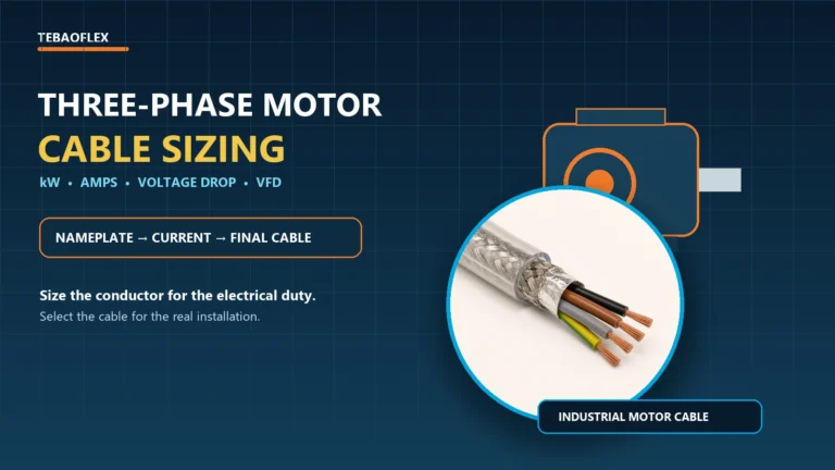
Conventional cable sizing remains necessary. The cable must carry drive output current under the installed thermal conditions, withstand fault energy and keep running and starting voltage within the project requirements. Our three-phase motor cable sizing guide explains the current, power factor, efficiency, derating and voltage-drop workflow.
Increasing conductor area reduces resistance and usually improves voltage drop and I²R loss. It does not automatically fix pulse reflection. A larger cable can have different capacitance and characteristic impedance, and the drive’s allowed cable length may still depend on filtering and grounding. Treat conductor size and high-frequency compatibility as two connected but distinct design tasks.
| Check | Main inputs | Typical corrective action |
|---|---|---|
| Ampacity | Drive current, harmonics, installation, ambient temperature and grouping | Change conductor size, cable rating or installation |
| Voltage drop | Current, one-way length, R, X, motor power factor and operating condition | Increase conductor area or reduce route length |
| I²R power loss | Actual current and operating conductor resistance | Increase area or improve operating conditions |
| Reflected-wave stress | Rise time, propagation delay, cable and motor surge impedance | Apply manufacturer-approved reactor or filter; review cable/system |
| EMC/common mode | Screen transfer impedance, PE path, terminations, bonding and routing | Improve cable construction and installation practice |
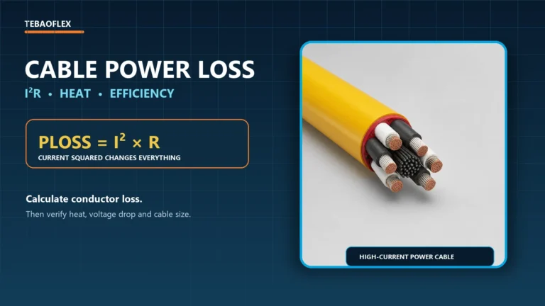
For conventional calculations, use verified cable R and X data rather than a nominal area alone. The cable voltage-drop calculation guide covers single-phase and three-phase formulas, while the cable power-loss guide explains why real conductor loss is based principally on I²R.
Long VFD Cable, Capacitance and Drive Output Current
Every motor cable has capacitance between conductors and from conductors to screen or earth. Total capacitance grows approximately with length for a consistent construction. The VFD must repeatedly charge and discharge that capacitance during switching. Longer cable can therefore increase high-frequency output current and common-mode current, affect protective functions and contribute to nuisance trips.
“Low capacitance” is useful only when it is supported by product data and evaluated with the actual length. The drive manual may specify a maximum total cable capacitance or a length limit for a stated cable type. Parallel cables and multi-motor arrangements can increase the total seen by the drive. If several motors are connected, check whether the manufacturer requires the branch lengths, total length, or both to be considered.
Shielded vs Unshielded VFD Motor Cable Length
Shielding is central to many VFD EMC strategies, but a shield does not automatically permit a longer route. A screened cable can have higher capacitance than an otherwise similar unscreened cable. Some drive manuals list different maximum lengths for shielded and unshielded constructions because output loading and EMC conditions differ.
The cable screen must also be part of a low-impedance high-frequency return path. Long pigtails add inductance and can compromise the screen at switching frequencies. For compatible systems, 360-degree termination at the drive and motor is commonly used, together with a continuous protective-earth conductor and equipotential bonding. ABB’s ACS480 hardware manual illustrates symmetrical shielded motor-cable construction and 360-degree shield grounding for applicable installations.
EMC, Grounding and Cable Routing
IEC 61800-3 covers EMC requirements and test methods for adjustable-speed power drive systems within its stated scope. The official IEC 61800-3:2022 page should be consulted for the current edition and scope. Compliance belongs to the installed power-drive system, not to one cable component in isolation.
A practical VFD installation normally reviews screen coverage and transfer impedance, protective-earth continuity, bonding between drive cabinet and motor frame, segregation from instrumentation and encoder circuits, crossing angles, metal tray continuity and termination hardware. Route power, brake and feedback circuits according to the equipment instructions. Avoid unnecessary loops and keep the screen continuous through suitable glands or connectors.
Motor Insulation and Bearing-Current Considerations
The motor must be suitable for the voltage waveform that reaches its terminals. Inverter-duty motors may provide enhanced winding insulation, but that label does not remove the need to follow the motor manufacturer’s stated peak-voltage and rise-time limits. Older motors, rewound motors and motors with unknown insulation history deserve particular attention before a long VFD cable is approved.
Common-mode voltage and high-frequency currents can also affect motor bearings and grounding paths. Cable length, cable symmetry, screen/PE arrangement, motor frame bonding, bearing design and mitigation devices all interact. A motor-terminal filter selected only for differential-mode dV/dt should not be assumed to solve every bearing-current or EMC problem.
Output Reactor vs dV/dt Filter vs Sine-Wave Filter
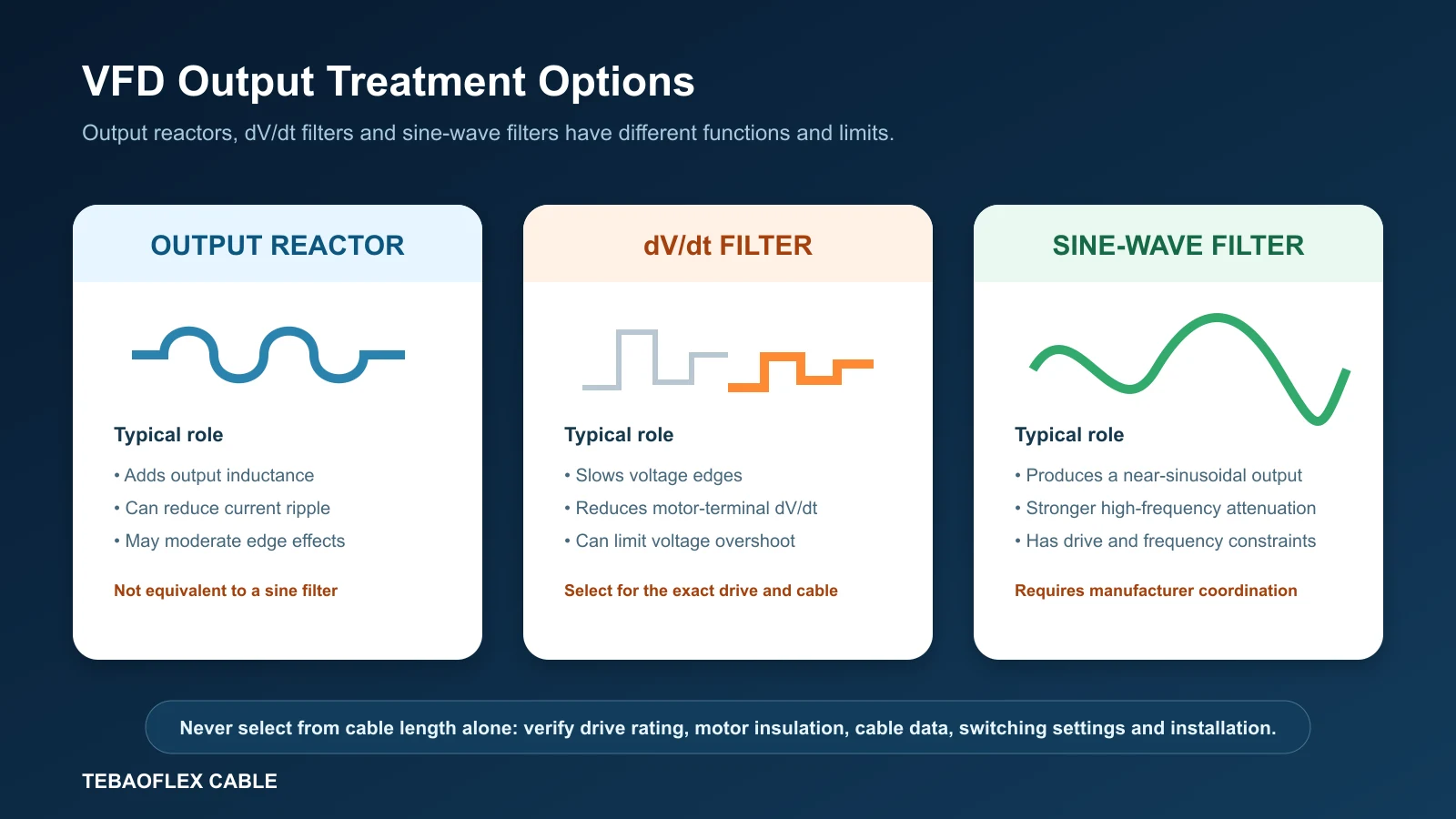
These devices are not interchangeable. An output reactor adds inductance and can reduce current ripple or moderate some edge effects. A dV/dt filter is designed to slow the voltage edge and limit motor-terminal stress. A sine-wave filter provides stronger attenuation of the PWM components so that the output approaches a sine wave. Each option introduces voltage drop, loss, heat and operating constraints that must be checked.
| Option | Primary purpose | Key checks before selection |
|---|---|---|
| Output reactor | Add output inductance; reduce current ripple or moderate some cable effects | Drive compatibility, current, inductance, voltage drop, heat and permitted cable length |
| dV/dt filter | Reduce edge steepness and motor-terminal voltage stress | Drive voltage/frame, cable length and capacitance, switching frequency, motor and filter rating |
| Sine-wave filter | Produce a near-sinusoidal motor voltage with stronger high-frequency attenuation | Output frequency range, switching frequency, motor/cable limits, filter loss, cooling and control method |
Do not set a rule such as “a dV/dt filter is mandatory beyond X metres” unless that number is taken from the exact drive documentation and all stated conditions are met. A different drive frame, cable type, voltage, motor or carrier setting can change the requirement.
Selecting Cable for Fixed, Drag-Chain and Reeling VFD Runs
Electrical suitability does not establish mechanical suitability. A fixed 2YSLCY-type motor cable should not be placed in a continuously moving energy chain unless its product data specifically approves that duty. Drag-chain cables need verified dynamic bend radius, travel, speed, acceleration, duty cycle and chain arrangement. Reeling cables need drum geometry, tension, travel speed, torsion, ambient and handling information.
For fixed or occasionally moved low-voltage connections, the 2YSLCY-JB shielded VFD motor cable is a 0.6/1 kV construction with Class 5 copper conductors, PE insulation, aluminium foil and tinned-copper braid screening. Its low-capacitance design can be a starting point, but the actual drive cable-length limit still comes from the drive–motor system.
For controlled continuous movement, the (N)GRDGCGOEU screened energy-chain cable provides a 0.6/1 kV flexible, tinned-copper-braid-screened construction for specified crane and material-handling chain systems. Its mechanical suitability does not by itself prove VFD compatibility; TEBAOFLEX should review the drive waveform, conductor arrangement, screen performance and motion data together.
For medium-voltage mobile equipment, the (N)TSCGEWOEU EMV FC VFD reeling cable covers rated-voltage classes from 3.6/6 kV to 12/20 kV and combines flexible conductors with an aluminium-foil and tinned-copper-braid EMC screen. Final selection requires the converter, motor, voltage class, conductor configuration, drum, bending radius and termination details.
The industrial automation cable application guide compares fixed, drag-chain, servo, feedback and VFD circuit duties. It is a useful starting point when the route includes both motor power and sensitive encoder or resolver signals.
Multi-Motor VFD Installations
One drive feeding several motors changes the cable model. The drive sees the combined cable capacitance and a network of branches and impedance discontinuities. Motor protection, current sharing, branch switching and individual motor overload protection also require engineering review. Some manufacturers specify the sum of all motor-cable lengths; others provide additional branch rules. Use the exact multi-motor instructions for the selected drive.
VFD Motor Cable Length Selection Workflow
- Identify the exact drive. Record manufacturer, model, frame, supply voltage, output current, control method, switching-frequency setting and approved output accessories.
- Define the motor. Record rated power/current, voltage, insulation or inverter-duty information, speed range, bearing arrangement and manufacturer limits.
- Measure the route. Use one-way drive-to-motor length and record branches, parallel cables, intermediate terminals, disconnects and connectors.
- Select the movement class. Confirm fixed, occasional flex, drag chain, festoon, reeling or torsional operation before choosing a product family.
- Complete ordinary cable checks. Verify ampacity, derating, voltage drop, I²R loss, short-circuit withstand and protective coordination.
- Check the drive cable-length table. Match shielded/unshielded construction, frame size, switching conditions, motor count and filter configuration.
- Review high-frequency behaviour. Confirm cable capacitance, motor peak-voltage/rise-time limits, reflected-wave risk, common-mode current and EMC requirements.
- Specify grounding and termination. Define PE conductor, screen construction, 360-degree termination, bonding, tray and segregation.
- Coordinate an output solution if required. Select a reactor, dV/dt filter or sine-wave filter only with drive and filter documentation.
- Document assumptions. Keep the cable datasheet, drive table, motor limits, installation drawing and approval basis with the project file.
Common VFD Cable-Length Mistakes
- Using one maximum length for every drive. Limits vary by series, frame, voltage, filter and cable construction.
- Treating voltage drop as the only long-run issue. It does not evaluate reflected-wave or dV/dt stress.
- Assuming a larger conductor solves reflections. Area primarily changes resistance; the high-frequency network still needs review.
- Assuming shielded cable always allows a longer run. Screening supports EMC but can change cable capacitance.
- Confusing switching frequency with rise time. They describe different aspects of the PWM output.
- Using pigtail screen terminations. Their inductance can reduce high-frequency screening effectiveness.
- Ignoring total cable length in multi-motor systems. Combined capacitance and branches can be decisive.
- Choosing a fixed cable for continuous motion. Electrical compatibility does not prove flex-life suitability.
VFD Motor Cable Length FAQ
What is the maximum VFD motor cable length?
There is no universal maximum. Use the exact drive manual and match drive frame, cable type, shielding, motor, switching settings, filter and multi-motor conditions.
Why does a long VFD cable increase motor voltage?
Fast PWM edges travel along the cable and can reflect at the motor because the cable and motor have different high-frequency impedances. Incident and reflected components can add at the terminals.
Does a larger cable eliminate reflected waves?
No. A larger area reduces resistance and voltage drop, but reflections depend on rise time, propagation delay, characteristic impedance, motor surge impedance and system termination.
When is a dV/dt filter required?
It is required when the drive and motor documentation or an engineering assessment calls for it. The decision can depend on cable length, capacitance, voltage, motor insulation, rise time and switching settings.
Is an output reactor the same as a dV/dt filter?
No. A reactor mainly adds inductance; a dV/dt filter is designed to slow voltage edges. Their attenuation, voltage drop and application limits differ.
Does shielded VFD cable prevent reflected waves?
No. A screen supports EMC and provides a controlled high-frequency return path when terminated correctly, but it does not remove the cable–motor impedance mismatch.
Can VFD cable length cause drive trips?
Yes. Added cable capacitance and common-mode current can contribute to overcurrent or earth-fault trips, depending on the drive, cable, grounding and protection settings.
Should VFD cable screens be grounded at both ends?
Many industrial VFD installations use low-impedance 360-degree screen termination at the drive and motor, but the equipment manual and site bonding design govern the final arrangement.
How is cable length handled for several motors on one VFD?
Follow the drive’s multi-motor instructions. The manufacturer may require the total of all branch lengths, combined capacitance and specific branch or output-filter arrangements.
Can a fixed VFD cable be used in a drag chain?
Only if its product data specifically approves the required continuous-flex duty. Otherwise select a drive-compatible energy-chain cable using travel, bend radius, speed, acceleration and cycle data.
Need Help Specifying a VFD Motor Cable for a Long Run?
Send TEBAOFLEX the VFD manufacturer and model, system voltage, motor rating and current, motor insulation information, one-way cable length, conductor size, screen/EMC requirement, proposed reactor or filter, and whether the cable is fixed, drag-chain, festoon or reeling. The technical team can review the electrical construction, mechanical duty and RFQ data together.
Engineering note: this article explains selection principles and does not replace the VFD, filter, motor and cable manufacturers’ project-specific limits or approval by the responsible engineer.