

What Is BFOU Cable?
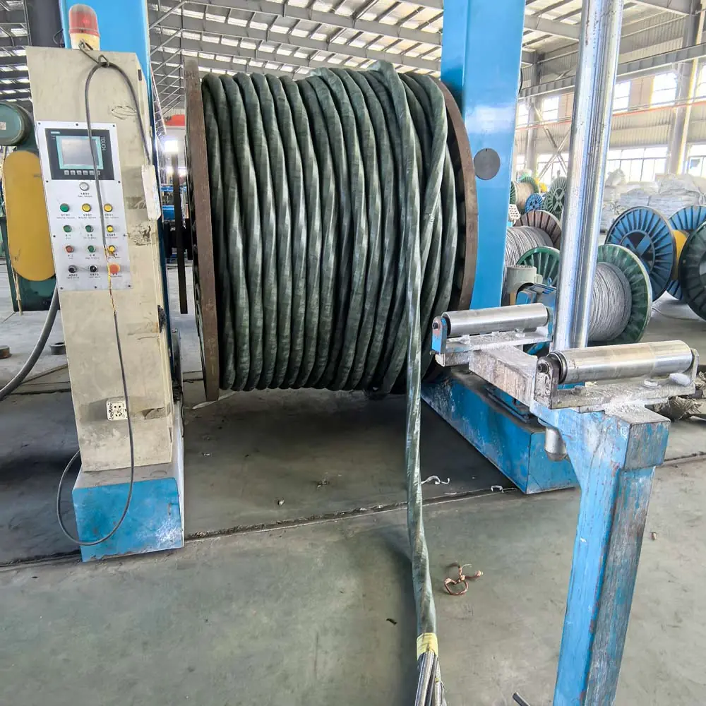
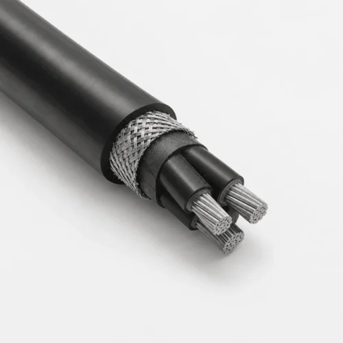
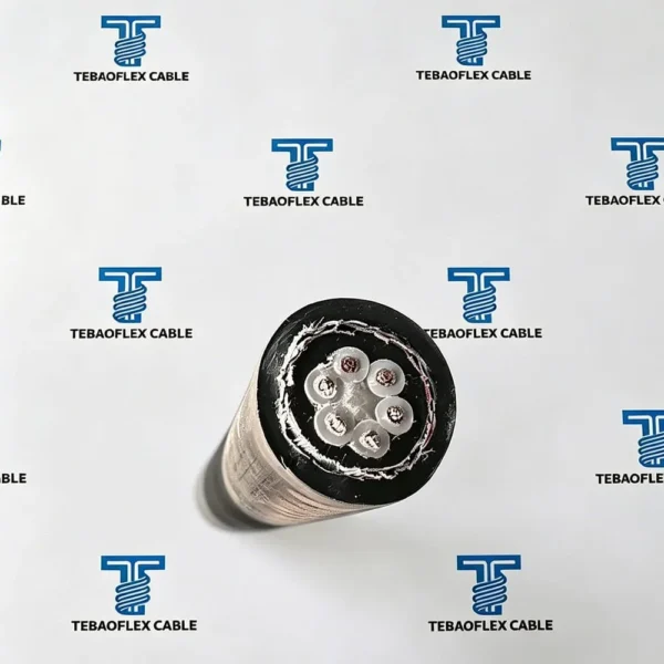
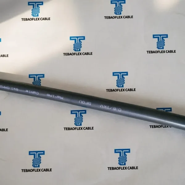
BFOU cable is a 0.6/1 kV fire-resistant, halogen-free and mud-resistant power cable for fixed offshore and marine installations. Its listed construction combines a Class 2 stranded tinned-copper conductor, mica-glass fire barrier, halogen-free EPR insulation, halogen-free bedding, tinned-copper wire braid and a black SHF2 MUD elastomer sheath. It is specified for critical power distribution, emergency lighting and other circuits where the project requires circuit integrity during a defined fire test.
BFOU is a construction family, not automatic approval for every vessel or platform. Confirm conductor size, core count, route, current rating, voltage drop, fire-survival requirement, mud and oil exposure, gland arrangement and the exact test documents. Review the BFOU cable specification guide or ask the TEBAOFLEX offshore cable team to check the project cable schedule.
Where Is BFOU Cable Used?
BFOU is used in fixed offshore and marine routes where a fire-resistant cable is required for critical circuits. Typical applications include emergency power, fire and gas systems, shutdown systems, emergency lighting, communication support equipment and essential electromechanical loads, subject to the approved cable schedule.
- Fire-resistant construction with mica glass tape for critical marine power circuits.
- Halogen-free EPR insulation and SHF2 MUD sheath for offshore and shipboard environments.
- Tinned copper wire braid screen for electrical protection in power distribution routes.
- Suitable for fixed installation in emergency systems, lighting systems and electromechanical equipment.
- TEBAOFLEX supports customized core count, conductor size and project documentation for marine and offshore cable procurement.
See the BFOU offshore applications guide, oil, gas and marine cable solutions and the marine cable range for related fixed-installation designs.
How Is BFOU Cable Constructed and Rated?
| Parameter | Specification |
|---|---|
| Rated voltage Uo/U | 0.6/1kV |
| Test voltage | 3.5kV |
| Temperature rating | -40C to +90C |
| Minimum bending radius | 8 x overall diameter |
| Conductor | Class 2 stranded tinned copper conductor |
| Fire barrier | Mica glass tape |
| Insulation | Halogen-free EPR |
| Bedding | Halogen-free compound |
| Screen | TCWB tinned copper wire braid |
| Outer sheath | Black SHF2 MUD halogen-free elastomer |
Which Standards and Fire Tests Apply?
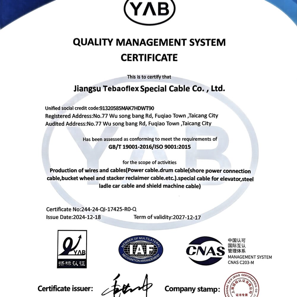
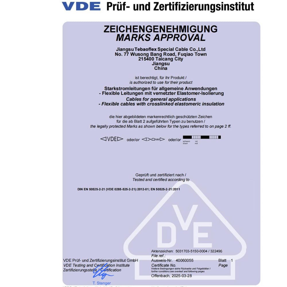
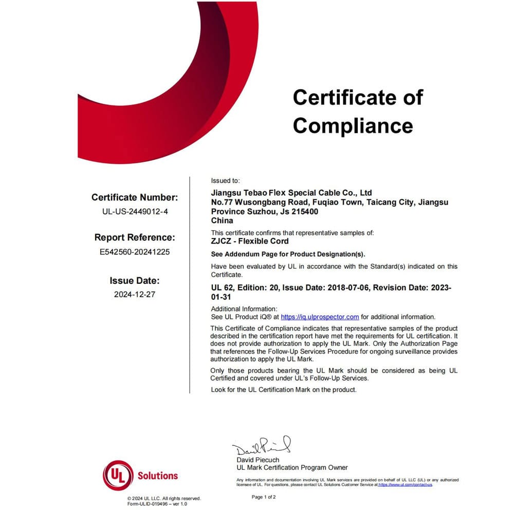
This BFOU marine power cable is specified around recognized shipboard and offshore cable requirements, including IEC 60092-353 for rated voltage 1kV shipboard power cables and NEK 606 offshore cable practice. Relevant fire, flame and halogen-free references include IEC/EN 60331, IEC/EN 60332-3-22, IEC/EN 60332-1-2, IEC/EN 61034-2 and IEC/EN 60754-1/2. Final compliance documents should be confirmed against the requested project specification.
Which BFOU Cable Sizes Are Listed?
Use these nominal dimensions as an initial selection guide. However, confirm the final configuration, current rating and project documentation with TEBAOFLEX before ordering.
Single-Core BFOU Cable Sizes
| Cores | Nominal cross section | Approx. overall diameter | Approx. cable weight |
|---|---|---|---|
| 1 core | 1.5 mm2 | 9.3 mm | 150 kg/km |
| 1 core | 2.5 mm2 | 9.8 mm | 170 kg/km |
| 1 core | 4 mm2 | 10.4 mm | 200 kg/km |
| 1 core | 6 mm2 | 10.9 mm | 230 kg/km |
| 1 core | 10 mm2 | 11.9 mm | 290 kg/km |
| 1 core | 16 mm2 | 13 mm | 380 kg/km |
| 1 core | 25 mm2 | 15.4 mm | 550 kg/km |
| 1 core | 35 mm2 | 16.6 mm | 670 kg/km |
| 1 core | 50 mm2 | 18.1 mm | 860 kg/km |
| 1 core | 70 mm2 | 20.1 mm | 1110 kg/km |
| 1 core | 95 mm2 | 22.4 mm | 1420 kg/km |
| 1 core | 120 mm2 | 24.4 mm | 1710 kg/km |
| 1 core | 150 mm2 | 26.5 mm | 2050 kg/km |
| 1 core | 185 mm2 | 28.8 mm | 2480 kg/km |
| 1 core | 240 mm2 | 31.6 mm | 3160 kg/km |
| 1 core | 300 mm2 | 35 mm | 3850 kg/km |
Two-Core BFOU Cable Sizes
| Cores | Nominal cross section | Approx. overall diameter | Approx. cable weight |
|---|---|---|---|
| 2 core | 1.5 mm2 | 14.2 mm | 320 kg/km |
| 2 core | 2.5 mm2 | 15.2 mm | 380 kg/km |
| 2 core | 4 mm2 | 16.4 mm | 450 kg/km |
| 2 core | 6 mm2 | 17.5 mm | 530 kg/km |
| 2 core | 10 mm2 | 19.5 mm | 720 kg/km |
| 2 core | 16 mm2 | 21.7 mm | 890 kg/km |
| 2 core | 25 mm2 | 25.5 mm | 1280 kg/km |
| 2 core | 35 mm2 | 28 mm | 1580 kg/km |
| 2 core | 50 mm2 | 31 mm | 2050 kg/km |
Three-Core BFOU Cable Sizes
| Cores | Nominal cross section | Approx. overall diameter | Approx. cable weight |
|---|---|---|---|
| 3 core | 1.5 mm2 | 14.9 mm | 360 kg/km |
| 3 core | 2.5 mm2 | 16 mm | 430 kg/km |
| 3 core | 4 mm2 | 17.3 mm | 520 kg/km |
| 3 core | 6 mm2 | 18.4 mm | 620 kg/km |
| 3 core | 10 mm2 | 20.7 mm | 820 kg/km |
| 3 core | 16 mm2 | 23 mm | 1070 kg/km |
| 3 core | 25 mm2 | 27.2 mm | 1850 kg/km |
| 3 core | 35 mm2 | 29.8 mm | 1960 kg/km |
| 3 core | 50 mm2 | 33.1 mm | 2580 kg/km |
| 3 core | 70 mm2 | 38.3 mm | 3450 kg/km |
| 3 core | 95 mm2 | 43.2 mm | 4480 kg/km |
| 3 core | 120 mm2 | 48 mm | 5650 kg/km |
| 3 core | 150 mm2 | 52.4 mm | 6800 kg/km |
| 3 core | 185 mm2 | 57.5 mm | 8400 kg/km |
| 3 core | 240 mm2 | 64 mm | 10810 kg/km |
Four-Core BFOU Cable Sizes
| Cores | Nominal cross section | Approx. overall diameter | Approx. cable weight |
|---|---|---|---|
| 4 core | 1.5 mm2 | 16.1 mm | 430 kg/km |
| 4 core | 2.5 mm2 | 17.3 mm | 510 kg/km |
| 4 core | 4 mm2 | 18.7 mm | 620 kg/km |
| 4 core | 6 mm2 | 20 mm | 740 kg/km |
| 4 core | 10 mm2 | 22.6 mm | 1000 kg/km |
| 4 core | 16 mm2 | 25.1 mm | 1320 kg/km |
| 4 core | 25 mm2 | 29.8 mm | 1960 kg/km |
| 4 core | 35 mm2 | 32.7 mm | 2450 kg/km |
What Is the BFOU Conductor Resistance?
The table provides maximum conductor resistance values at 20°C for the listed Class 2 and optional Class 5 conductor references. Confirm the conductor class on the approved data sheet because resistance, diameter and flexibility differ.
| Nominal cross section | Class 2 max resistance at 20C | Class 5 max resistance at 20C |
|---|---|---|
| 0.5 mm2 | 36.7 ohm/km | 40.1 ohm/km |
| 0.75 mm2 | 24.8 ohm/km | 26.7 ohm/km |
| 1 mm2 | 18.2 ohm/km | 20 ohm/km |
| 1.5 mm2 | 12.2 ohm/km | 13.7 ohm/km |
| 2.5 mm2 | 7.56 ohm/km | 8.21 ohm/km |
| 4 mm2 | 4.7 ohm/km | 5.09 ohm/km |
| 6 mm2 | 3.11 ohm/km | 3.39 ohm/km |
| 10 mm2 | 1.84 ohm/km | 1.95 ohm/km |
| 16 mm2 | 1.16 ohm/km | 1.24 ohm/km |
| 25 mm2 | 0.734 ohm/km | 0.795 ohm/km |
| 35 mm2 | 0.529 ohm/km | 0.565 ohm/km |
| 50 mm2 | 0.391 ohm/km | 0.393 ohm/km |
| 70 mm2 | 0.27 ohm/km | 0.277 ohm/km |
| 95 mm2 | 0.195 ohm/km | 0.210 ohm/km |
| 120 mm2 | 0.154 ohm/km | 0.164 ohm/km |
| 150 mm2 | 0.126 ohm/km | 0.132 ohm/km |
| 185 mm2 | 0.1 ohm/km | 0.108 ohm/km |
| 240 mm2 | 0.0762 ohm/km | 0.0817 ohm/km |
| 300 mm2 | 0.0607 ohm/km | 0.0654 ohm/km |
What Is the Current-Carrying Capacity of BFOU Cable?
The values below are reference current ratings, not universal project ampacities. Final conductor size depends on ambient temperature, grouping, tray arrangement, ventilation, route length, voltage drop, short-circuit duty and applicable project rules. Use the cable ampacity calculation guide for planning, then confirm the project calculation.
| Nominal cross section | Single core | 2 core | 3 and 4 core | 5 core |
|---|---|---|---|---|
| 1 mm2 | 18 A | 15 A | 13 A | 11 A |
| 1.5 mm2 | 23 A | 20 A | 16 A | 13 A |
| 2.5 mm2 | 30 A | 26 A | 21 A | 18 A |
| 4 mm2 | 40 A | 34 A | 28 A | 23 A |
| 6 mm2 | 52 A | 44 A | 36 A | 30 A |
| 10 mm2 | 72 A | 61 A | 50 A | 42 A |
| 16 mm2 | 96 A | 82 A | 67 A | 56 A |
| 25 mm2 | 127 A | 108 A | 89 A | 74 A |
| 35 mm2 | 157 A | 133 A | 110 A | 92 A |
| 50 mm2 | 196 A | 167 A | 137 A | 115 A |
| 70 mm2 | 242 A | 206 A | 169 A | 142 A |
| 95 mm2 | 293 A | 249 A | 205 A | 171 A |
| 120 mm2 | 339 A | 288 A | 237 A | 198 A |
| 150 mm2 | 389 A | 331 A | 273 A | 227 A |
| 185 mm2 | 444 A | 377 A | 311 A | 260 A |
| 240 mm2 | 522 A | 444 A | 366 A | 305 A |
| 300 mm2 | 601 A | 511 A | 420 A | 351 A |
What Offshore Environments Use BFOU Cable?
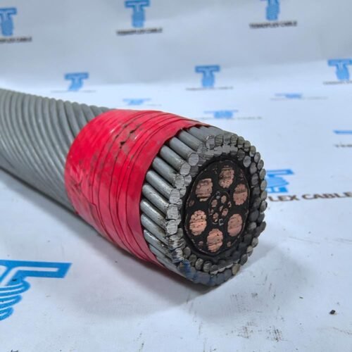
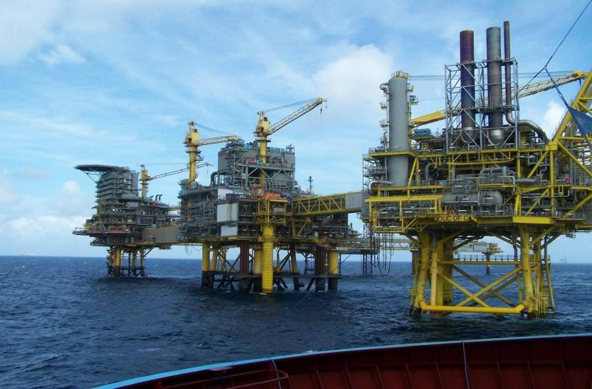
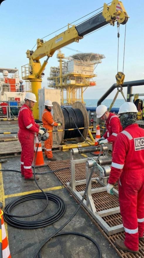
These images illustrate offshore and marine environments where a project may specify BFOU 0.6/1kV for fixed critical power routes. The installation shown does not by itself prove suitability; route, fire requirement, mechanical protection, gland system and certification scope must be confirmed.
How Do You Select the Correct BFOU Cable?
1. Define the critical circuit
State the circuit function, required operating time during fire, system voltage, load current, protective-device data and equipment served. Fire resistance must match the project safety philosophy and specified test method.
2. Calculate conductor size and core count
Provide load current, route length, allowable voltage drop, installation method, grouping, ambient temperature and short-circuit duty. Include neutral and protective-earth requirements.
3. Confirm the fire-performance specification
List the exact IEC or EN fire-resistance, flame-propagation, smoke and halogen requirements, including the required test duration and project document edition.
4. Describe the fixed installation route
Identify cable tray, conduit, open deck, enclosed space, vertical route, support spacing and gland entry. BFOU is intended for fixed installation, not continuous flexing or reeling.
5. Describe environmental exposure
State mud, oil, drilling fluids, salt atmosphere, water, sunlight, chemicals and temperature. Confirm the required test method for the selected SHF2 MUD sheath.
6. Specify documents and delivery
Provide class or third-party requirements, inspection plan, test reports, marking, drum length, packing, quantity, destination and required delivery date.
What Is the Difference Between BFOU and RFOU Cable?
BFOU includes a fire barrier and is reviewed where the circuit must maintain integrity during a defined fire test. RFOU is flame retardant but is not the same circuit-integrity construction. Both can be halogen-free and mud resistant, so the cable name, test requirement and approved construction must all be compared. See the RFOU versus BFOU comparison.
Installation Limits and Engineering Notes
- Use the cable only within the approved voltage, temperature, bend radius and environmental limits.
- Do not treat reference ampacity values as a substitute for the project cable-sizing calculation.
- Confirm braid earthing, gland compatibility, support spacing and mechanical protection.
- Do not use BFOU for continuous flexing, reeling or trailing service without a separate engineering assessment.
- Verify certification and test documents for the exact ordered construction.
Frequently Asked Questions
What does BFOU cable mean?
BFOU is an offshore and marine cable designation associated with a fire-resistant, halogen-free, braided and mud-resistant fixed-installation construction. The approved data sheet defines the exact structure and compliance scope.
Is BFOU cable fire resistant or only flame retardant?
The listed BFOU construction includes a mica-glass fire barrier for circuit integrity during a specified fire test. It also has flame-retardant characteristics, but the two terms describe different test objectives.
Can BFOU cable be used in drilling mud?
The listed SHF2 MUD sheath is intended for mud-resistant offshore service. Confirm the fluid, exposure, test method and documentation required for the ordered cable.
Can BFOU be used as a flexible or reeling cable?
No, not by designation alone. BFOU is intended for fixed installation. Continuous flexing, reeling and trailing applications require a cable specifically designed for that movement.
What bending radius applies?
The listed minimum bending radius is eight times the overall cable diameter. Installation conditions, glands and route geometry must also be checked.
What information is needed for a quotation?
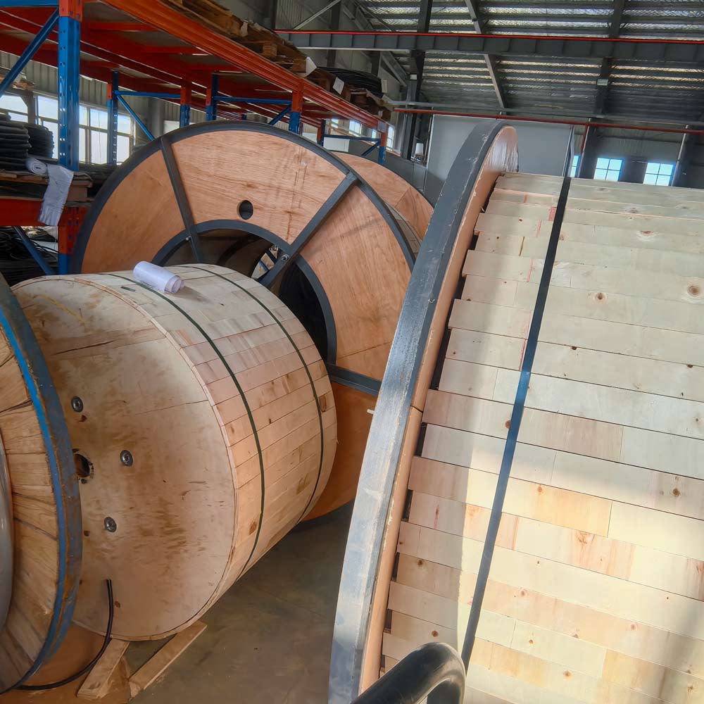
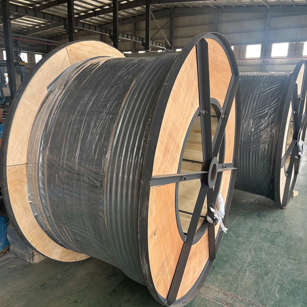
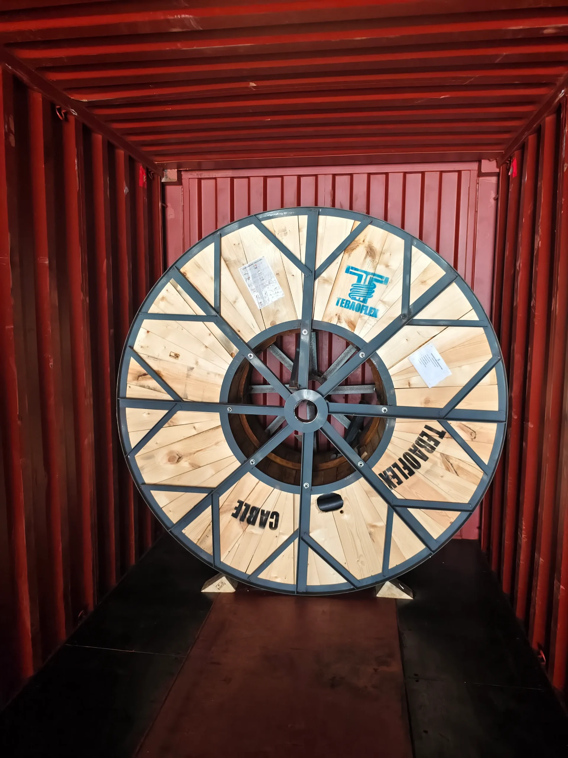
Send the circuit function, fire test, voltage, core count, conductor size, route, environmental exposure, standards, documents, drum length, quantity, destination and delivery date.
Request a BFOU Cable Specification and Quotation
Submit the cable schedule and fire-performance requirements so the conductor size, core arrangement, construction, dimensions, ampacity and project documents can be reviewed before quotation.