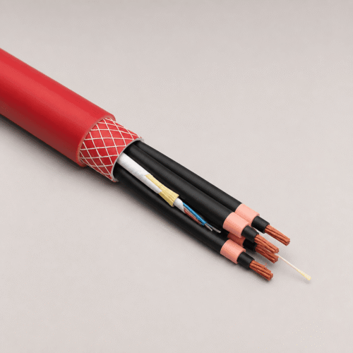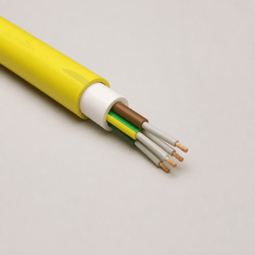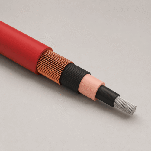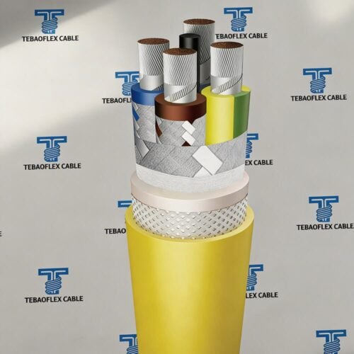


Product Overview: S1BZ5-F is a flexible Mode 4 DC EV fast-charging cable carrying a 1.5 kV DC application designation on a 600/1000 V rated construction referenced to IEC 62893-4-1 (Type 62893 IEC 126), uniting Class 5 copper DC+/DC- and PE conductors, CC/CP pilot pairs, and an outdoor-durable black TPU Type EVM-1 outer sheath.
1. Application & S1BZ5-F (DC) vs. H07BZ5-F (AC) Scope
S1BZ5-F is engineered specifically as the handled tethered lead between a stationary DC fast-charging dispenser and the vehicle inlet connector (uncooled assembly builds):
- Mode 4 Public & Commercial DC Chargers: Highway fast-charging plazas, fleet depot dispensers, heavy-truck charging hubs, and OEM connector cable assemblies.
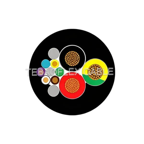
- Integrated Power + Pilot Signalling: Combines positive/negative DC power cores (
35–95 mm²), protective earth (PE), and0.75–1.5 mm²CC/CP control/proximity pairs inside a single ergonomic jacket. - Sub-Zero & Forecourt Handling: Remains flexible down to -40°C while resisting forecourt oils, UV, ozone, and tarmac abrasion.
DC vs. AC EV Charging Selection: Do not substitute S1BZ5-F and H07BZ5-F interchangeably. Specify S1BZ5-F for Mode 4 DC charging up to 1.5 kV DC; for 450/750 V AC charging assemblies (Modes 1–3), compare H07BZ5-F PUR AC EV Charging Cable or browse our Rubber & Flexible Cables range.
2. Cable Construction (IEC 62893-4-1 Hierarchy)
Exact DC+/DC-, PE, and CC/CP pin assignments must be verified against the charger schematic and vehicle connector drawing before manufacture:
0.75 mm² or 1.5 mm² EVI-2 insulated control pairs/quads supporting pilot, proximity, and temperature-monitoring circuits.3. Electrical, Thermal & Environmental Characteristics
Standards below serve as construction and test references—request conformity or third-party test reports matching your destination market and exact cross-section on the RFQ:
| Technical Parameter | Reference Standard / Value |
|---|---|
| Design Reference | IEC 62893-4-1, Type 62893 IEC 126; core identification per IEC 62893-1 |
| Rated Voltage & DC Application | 600/1000 V nominal rating; 1.5 kV DC charging application designation |
| Fully Flexible Ambient Temp. | -40°C to +60°C |
| Max. Conductor Temperature | 90°C continuous (up to 120°C temporary only where explicitly approved on project datasheet) |
| Tensile & Bending Rules | Max. 15 N/mm² copper tensile stress; minimum bend radius per DIN VDE 0298-3 |
| Flame, Oil, Ozone & Halogen | DIN EN 60332-1-2 flame; DIN EN 60811-404 oil; DIN EN 50396 §8.1.3 ozone; EN 50525-1 Annex B / IEC 62821-1 halogen-free |
4. Reference Core Configurations & Ordering SKU Table
Reference insulation/sheath thicknesses, approximate outside diameters, and cable weights (final connector gland tolerances are confirmed on the approved production drawing):
| Part SKU | Core Configuration (mm²) | Nominal EVI-2 Insulation (mm) | Approx. EVM-1 Sheath (mm) | Approx. Outer Diameter (mm) | Approx. Weight (kg/km) |
|---|---|---|---|---|---|
TF-S1B-3G16 | 3G16 + 3 × (2 × 0.75) | 0.8 | 1.5 | 20.6 | 680 |
TF-S1B-2X35-16 | 2 × 35 + 1G16 + 3 × (2 × 0.75) | 1.0 | 1.9 | 24.8 | 1,205 |
TF-S1B-2X35-Q | 2 × 35 + 1G16 + 1 × (4 × 0.75) + 2 × (2 × 0.75) | 1.0 | 1.9 | 25.8 | 1,350 |
TF-S1B-2X35-25 | 2 × 35 + 1G25 + 3 × (2 × 0.75) | 1.0 | 1.9 | 26.0 | 1,275 |
TF-S1B-2X50 | 2 × 50 + 1G25 + 3 × (2 × 0.75) | 1.1 | 2.2 | 27.9 | 1,600 |
TF-S1B-2X70-P | 2 × 70 + 1G35 + 3 × (2 × 0.75) | 1.2 | 2.5 | 32.7 | 2,150 |
TF-S1B-2X70-6C | 2 × 70 + 1G35 + 6 × 0.75 | 1.2 | 2.5 | 32.7 | 2,150 |
TF-S1B-2X95 | 2 × 95 + 1G50 + 3 × (2 × 0.75) | 1.2 | 2.7 | 41.0 | 2,400 |
TF-S1B-5G50 | 5G50 + 6 × 1.5 | 1.1 | 2.2 | 36.4 | 3,065 |
5. Frequently Asked Questions
Is S1BZ5-F suitable for Mode 4 DC EV fast charging?
Yes. S1BZ5-F is engineered for tethered Mode 4 DC EV charging dispenser leads—confirm continuous/peak current, connector model, and CC/CP pinout prior to production.
Why does S1BZ5-F list both 600/1000 V and 1.5 kV DC?
Under IEC 62893-4-1 (Type 62893 IEC 126), the cable carries a 600/1000 V nominal construction rating alongside a 1.5 kV DC EV charging application designation.
How does S1BZ5-F differ from H07BZ5-F?
S1BZ5-F is built for high-power DC charging with dedicated DC+/DC- and CC/CP signal structures, whereas H07BZ5-F is a 450/750 V AC charging cable.
Can S1BZ5-F operate in freezing outdoor forecourts?
Yes—it is rated down to -40°C in fully flexible operation (+60°C max ambient, 90°C continuous conductor) with UV, ozone, and DIN EN 60811-404 oil resistance.
Can sheath colour or custom marking be specified?
Black TPU Type EVM-1 is the standard compound; custom sheath colours, OEM branding print, and cut/bulk drum lengths can be reviewed against technical compliance and MOQ.
What details should I submit for an S1BZ5-F quotation?
Send DC voltage/current, connector type, DC+/DC-/PE cross-sections, CC/CP pair layout, lead or drum length, quantity, destination country, and required test documentation.
Request S1BZ5-F 1.5 kV DC Charging Cable Drawing & Quote
Share your charger DC current, connector specification, and required DC+/DC-/PE + CC/CP core build. TEBAOFLEX will confirm finished gland OD and issue a factory quotation.