Executive summary: A mining power inquiry for Mexico specified a 2,000 V Type G-GC round portable trailing cable built with 3 × 4/0 AWG phase conductors, 2 × 2 AWG symmetrical grounding conductors, and 1 × 8 AWG insulated ground-check pilot wire. Matching ICEA S-75-381 core geometry, pilot-relay compatibility, jacket compound, and reel-layer ampacity derating prevents field mis-termination.
How Is a 3 × 4/0 + 2 × 2 + 1 × 8 AWG Type G-GC Cable Structured Under ICEA S-75-381?
Under ICEA S-75-381 / NEMA WC 58, a 2,000 V Type G-GC portable power cable combines three insulated phase conductors with two split equipment-grounding conductors and one insulated ground-check (GC) pilot conductor laid in the outer interstices. In the 4/0 AWG size requested for Mexico, the three phase cores total roughly 321.6 mm² of copper while the two 2 AWG grounds provide 67.2 mm² of protective earth capacity.
Splitting the protective earth into two symmetrical 2 AWG green-insulated conductors keeps the cable cross-section round, balances mechanical bending stress, and exceeds the 50% single-phase cross-section benchmark required for portable mining equipment grounding. Placing an 8 AWG (8.37 mm²) yellow-insulated ground-check conductor in the third interstice adds tensile survival margin compared with thinner 10 AWG pilot wires used on smaller sizes, reducing nuisance trip shutdowns caused by internal pilot-core necking under trailing tension. Engineers converting North American mining gauges to metric cross-sections can cross-check values in our AWG-to-mm² conductor sizing and current rating guide and our flexible cable protective earth conductor sizing guide.
| Core Element | Mexico Project Callout | Metric Equivalent | ICEA S-75-381 / Sample Construction Details |
|---|---|---|---|
| Phase conductors (3 cores) | 3 × 4/0 AWG | 3 × 107.2 mm² | Rope-lay flexible tinned copper (ASTM B33 / B172); 90 °C EPR insulation (black, white, red) |
| Equipment grounds (2 cores) | 2 × 2 AWG | 2 × 33.6 mm² (67.2 mm² total) | Stranded tinned copper in two outer interstices; green covering; combined area = 62.7% of one phase |
| Ground-check pilot (1 core) | 1 × 8 AWG | 1 × 8.37 mm² | High-strength stranded tinned copper in third interstice; yellow EPR/PP insulation for pilot loop |
| Outer protective jacket | Heavy-duty black elastomer | Order-drawing governed OD | Sample printed TCU/EPR/CPE 90°C SUN OIL RES WET OR DRY; reinforced TSE optional by spec |
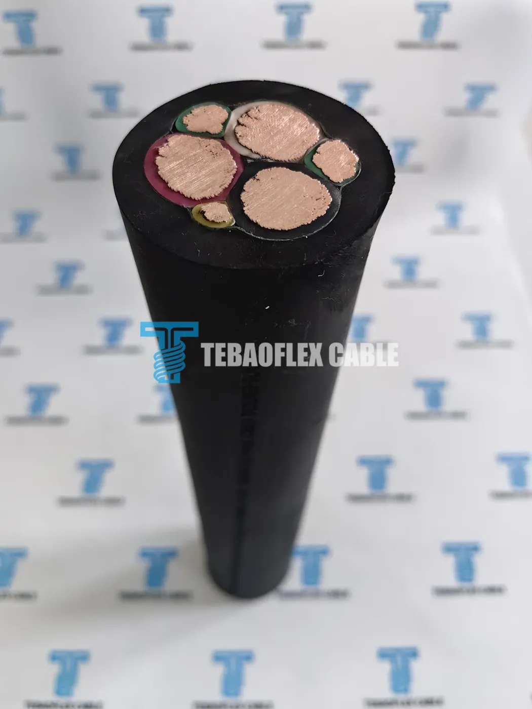
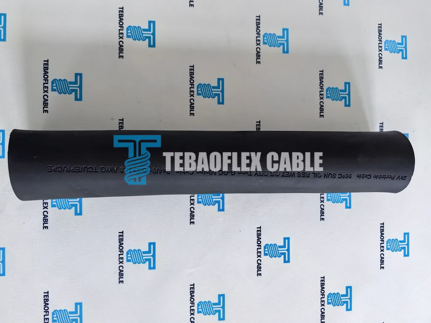
2kV Portable Cable 90°C SUN OIL RES WET OR DRY Type G-GC Mining Cable 3x4/0+2x2+1x8 AWG TCU/EPR/CPE.Why Must the Ground-Check Pilot Loop and Couplers Be Verified Together?
In mobile mining distribution, the two 2 AWG grounding conductors carry fault current and bond the machine frame, while the insulated 8 AWG ground-check core forms a low-voltage continuity loop back to the substation ground-check relay. If the cable is severed or a coupler pulls apart, the pilot pin opens first and trips the upstream breaker before power pins arc.
Ordering “4/0 Type G-GC” without specifying coupler pin geometry and relay type creates handover delays at the mine shop. Diode-terminated, impedance-sensing, and tone-loop ground monitors each impose specific loop-resistance and insulation thresholds on the GC circuit. The U.S. Mine Safety and Health Administration outlines how trailing-cable pilot loops verify ground continuity in its MSHA technical report on mine electrical grounding (cited here for engineering principle rather than regulatory jurisdiction in Mexico). Buyers can also step through relay and lug checks in our Type G-GC 2 kV ground-check cable selection guide.
How Do Jacket Compound, Reel Derating, and Shielding Boundaries Affect Final Selection?
Two engineering decisions frequently separate a generic catalog quote from a reliable mine cable specification: selecting between single-layer CPE and reinforced double-layer TSE jacketing, and calculating current derating when trailing cable operates partially wound on a mobile equipment reel.
Notice the distinction in the project records: the photographed sample carries a heavy-duty chlorinated polyethylene (CPE) jacket, whereas our standard Type G-GC 2 kV portable mining power cable product page highlights an integral cord-reinforced two-layer thermoset elastomer (TSE, such as PCP or CSP) for severe rock-drag and shuttle-car reeling. Both constructions are valid manufacturing builds, so purchase orders should explicitly lock the required elastomer compound, tear resistance, and oil/sunlight test standard.
Thermal limit warning: reel layer derating and the 2 kV shielding boundary
Under ICEA S-75-381 at 90 °C conductor temperature and 40 °C ambient air, a three-conductor 4/0 AWG portable cable has a free-air base ampacity near 287 A, but coiled layers trap heat rapidly. Industry practice applies approximate reel derating factors of 0.85 for 1 layer, 0.65 for 2 layers, and 0.45 for 3 layers remaining on the drum. In addition, Type G-GC has no metallic phase shields; if supply voltage exceeds 2,000 V or mine safety rules mandate per-phase fault shielding, specify Type SHD-GC shielded mining trailing cable or stationary Type MP-GC mine power feeder cable instead (see our SHD-GC mining cable selection guide).
| Verification Item | Recorded in Mexico Project Brief & Sample | Confirm on Signed Purchase Specification |
|---|---|---|
| Voltage & insulation | 2,000 V AC; 90 °C wet/dry cross-linked EPR phase insulation | System neutral grounding (resistance-grounded vs. solid) and factory AC spark/withstand test |
| Jacket compound | Black CPE marked on sample; reinforced TSE available | Lock single-extruded heavy CPE vs. fiber-reinforced dual-layer PCP/CSP/TPU per haul road abrasion |
| Ampacity & duty | 4/0 AWG power cores for heavy mobile mining machinery | Continuous load current, starting inrush, ambient mine temperature, and max layers left on reel |
| Couplers & pilot | 2 × 2 AWG ground + 1 × 8 AWG yellow GC core | Coupler shell entry range (OD tolerance), ground lug size, and pilot relay termination scheme |
| Flame & markings | Embossed/printed voltage, temperature, core schedule, and compound | Required flame-test listing (such as MSHA or FT4 equivalent) and custom meter/mine ID print |
What Do the Mining Context Footage and Export Packing Photographs Document?
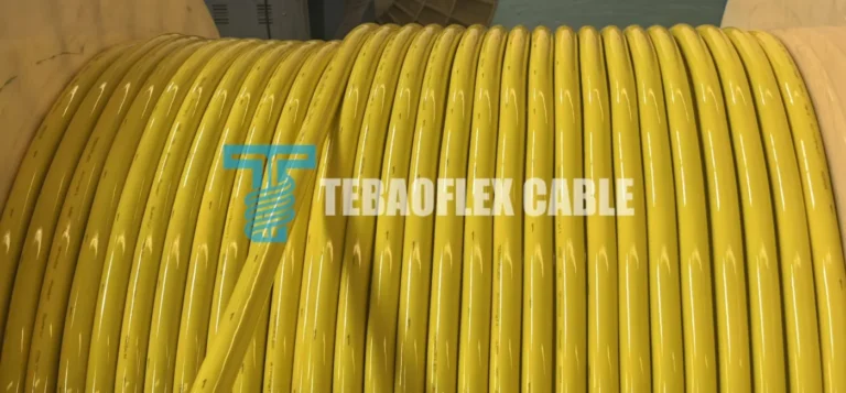
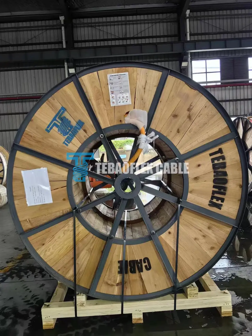
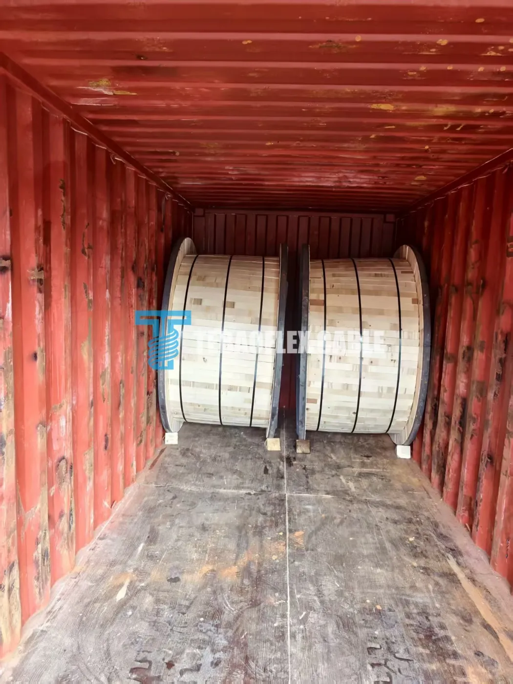
The project file pairs a short video of mobile mining equipment operating over rough ground with factory drum and container-loading photographs. These records illustrate the mechanical abuse that motivates heavy portable cable specifications and show export shipping preparation from our workshop.
Field operating stressors and RFQ preparation checklist
Presented for application context (rather than as footage filmed at the Mexican mine), the clip highlights crushed-rock abrasion, mud exposure, and abrupt cable flexing behind mobile machinery. To receive an engineered quotation across our mining cable solutions, include these project details:
- Complete core callout: State phase, ground, and pilot gauges explicitly (for example,
3 × 4/0 + 2 × 2 + 1 × 8 AWG). - Machine deployment mode: Specify free floor trailing, festoon carrier, or tensioned monospiral/cylindrical cable reel.
- Electrical load profile: Supply voltage, continuous amps, motor starting current, and one-way feeder run length.
- Jacket & environment: Choose standard heavy-duty CPE, reinforced two-layer TSE rubber, or high-tear TPU for sharp ore rock.
- Coupler & gland window: Minimum and maximum cable outside diameter accepted by existing mine plugs and strain reliefs.
- Reel cut lengths: Exact meters or feet per wooden drum, maximum drum gross weight for mine handling, and destination port.
Frequently Asked Questions
Does every 4/0 AWG Type G-GC cable use an 8 AWG ground-check conductor?
Under ICEA S-75-381 tables, 4/0 AWG Type G-GC commonly pairs two 2 AWG grounding conductors with an 8 AWG ground-check core (smaller phase sizes from 8 AWG through 2/0 AWG often use a 10 AWG or 8 AWG pilot depending on manufacturer build). Always write out all three conductor groups on purchase documents so coupler pins and crimp sleeves match on arrival.
When should a mine specify Type SHD-GC instead of 2 kV Type G-GC?
Type G-GC is unshielded and limited to 2,000 V maximum. Specify Type SHD-GC whenever system voltage exceeds 2 kV (such as 5 kV, 8 kV, 15 kV, or 25 kV shovels and draglines), when VFD-fed traction drives generate high-frequency common-mode noise, or when site electrical codes require grounded copper braid shields around each individual phase conductor.
Can free-air catalog ampacity be used directly when Type G-GC runs on a cable reel?
No. Catalog ampacity tables assume single-cable heat dissipation in 40 °C free air. Even two or three wraps left on a shuttle-car or drill reel restrict radial cooling and can push EPR insulation above its 90 °C limit. Apply reel-layer and ambient temperature derating factors before finalizing phase conductor gauge.
What do the sample and container photographs confirm for this Mexico inquiry?
They document the 3 × 4/0 + 2 × 2 + 1 × 8 AWG sample cross-section, the printed TCU/EPR/CPE jacket marking, and factory export drum loading practice. Signed order drawings, batch routine test reports, bill-of-lading quantities, and mine commissioning sign-off remain separate contract records.
Sourcing 2 kV Type G-GC or shielded SHD-GC trailing cable for mobile mining equipment?
Share your complete AWG core schedule, equipment deployment method (trailing or reeling), jacket preference (CPE, reinforced TSE, or TPU), and required drum lengths for a pre-quotation engineering review.
Request Mining Cable Drawing & QuoteSource & verification note: Based on the Mexico 2 kV Type G-GC project inquiry file, physical sample photographs, application-context video, and factory export-drum records. Dimensional and electrical benchmarks reference ICEA S-75-381 / NEMA WC 58 and MSHA ground-continuity engineering principles. Final jacket compound, outside diameter tolerances, routine test certificates, and site acceptance remain governed by signed purchase documentation. Reviewed by the TEBAOFLEX Engineering Team, October 2026.