When a downhole gauge, sensor, valve or other completion component must communicate with the surface for years in a hostile well environment, an ordinary industrial cable is rarely the right starting point. A TEC cable—short for tubing encapsulated cable—places the electrical conductor or conductors inside a continuous metal tube, optionally with an external polymer encapsulation. That architecture is used to protect a signal, power or combined signal-and-power path from the pressure, temperature, chemical and handling demands associated with downhole deployment.
For an engineer or buyer, “TEC” is not a complete specification. The useful question is: what must the completed cable survive, transmit and connect to throughout its intended service? This guide explains the TEC cable construction concept, where it is used, what to compare, frequent selection errors and the information that makes an RFQ actionable.

What is a TEC cable?
A tubing encapsulated cable is a compact, high-integrity cable system in which an insulated electrical conductor, multiple conductors, fibre or a combination of elements is enclosed within welded metal tubing. The metal tube is not just a conventional armour layer placed around a finished cable: it is a continuous protective barrier around the internal transmission element. Depending on the project, an outer polymer encapsulation may then be added to improve handling, abrasion behaviour or compatibility with the intended installation system.
TEC cable is commonly considered for permanent downhole monitoring and control tasks, including pressure and temperature gauges, completion instrumentation, intelligent-well components and other applications requiring a reliable path between subsurface equipment and surface systems. The exact electrical function determines whether the design prioritises conductor resistance, insulation performance, signal integrity, core count or a combination of these factors.
TEC cable is not a generic tray or flexible power cable
Its metal-tube construction, compact geometry and downhole operating context make TEC a different selection exercise from flexible rubber power cable, cable-tray cable or standard control cable. Do not assume that an oil-resistant jacket alone creates a TEC solution, and do not substitute a nominally similar cable when the completion drawing calls for tubing encapsulated construction. The cable, end fittings, splices, penetrators and installation method must work as one system.
Typical TEC cable applications
TEC is used where an electrical or optical path needs protection during installation and service in a well environment. Typical applications include:
- permanent downhole pressure and temperature monitoring;
- downhole gauge and sensor connections;
- control or communication paths for completion equipment;
- monitoring lines associated with artificial-lift or production-optimization systems; and
- custom multi-line assemblies where electrical conductors, fibres or capillary lines are combined around the production tubing.
The application still needs to be defined precisely. A monitoring line, a low-power sensor circuit and a power-bearing control circuit can have very different conductor, insulation and termination requirements even when each is described as a “downhole cable.”
TEC cable construction: the layers that need to be specified
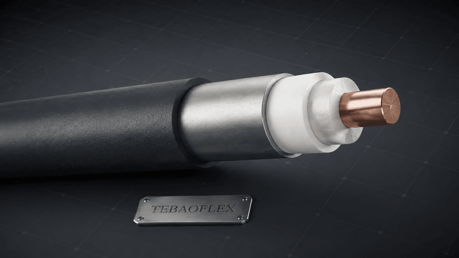
There is no single universal TEC construction. A typical arrangement may include a central conductor, one or more insulation layers, filler or centralising material, welded corrosion-resistant tubing and an optional external encapsulation. Each material choice must be tied to the actual operating environment and the customer’s approved specification.
| Construction element | Why it matters | What the buyer should define |
|---|---|---|
| Conductor and core count | Controls the electrical function, resistance and available circuits. | Signal, power or combined duty; conductor material and size; single or multi-conductor arrangement. |
| Insulation system | Must withstand the electrical and thermal environment inside the tubing. | Operating and transient temperature, voltage, dielectric requirements and any chemical-exposure information. |
| Filler or centraliser | Helps maintain the internal geometry and supports the insulated element within the tube. | Required cable geometry, signal considerations and applicable installation conditions. |
| Metal tubing | Provides the continuous protective tube and is a critical material-selection item. | Tube material, outside diameter, wall requirements, pressure profile, fluids, corrosive species and installation loads. |
| External encapsulation | May add protection for handling, abrasion and integration with the completion assembly. | Need for polymer type, profile, compatibility, clamp interface and handling protection. |
| Terminations and interfaces | System reliability depends on the connection as well as the cable body. | Connector, penetrator, splice, seal, reel and installation-interface drawings. |
How to select a TEC cable for the actual well environment
A reliable selection process starts with the environment, not a catalogue photo. First establish whether the cable will provide signal, power, data, fibre or a combined function. Then map the installation route and service exposure: planned depth, pressure profile, maximum and transient temperature, well fluids, gases, solids, completion hardware, cable clamps, deployment method and the intended service duration.
Material compatibility and sour-service information
Where the service contains hydrogen sulphide (H2S), the metallic tubing and other exposed metal components require a documented material-selection review. ISO 15156-1:2020 sets out general principles for selecting cracking-resistant materials in H2S-containing oil and gas production environments. It does not automatically certify a cable design: the equipment user must define the service conditions and confirm whether the standard applies to the complete project.
Electrical and signal requirements
Specify nominal voltage, circuit type, current where applicable, conductor size, number of cores and allowable electrical characteristics. For instrumentation and data circuits, include the sensor or tool interface, any shielding or grounding requirement, expected signal type and the maximum run length. For power-bearing circuits, define the load and duty cycle rather than requesting a cable only by outside diameter.
Mechanical handling and completion integration
Compact tubing encapsulated cable still has handling limits. Reel size, minimum bending guidance, pull or deployment forces, clamp spacing, crush exposure, edge contact, running speed and the method used to attach the cable to tubing can all affect the required design. These values must come from the installation procedure and completion engineer; they should not be guessed from a superficially similar TEC cable.
Common TEC cable selection mistakes
- Ordering by acronym only. “TEC cable” does not identify the conductor, tube material, outer encapsulation, interface or qualification plan.
- Leaving the well environment blank. Temperature, pressure, fluids and gas composition may be decisive for the cable system.
- Specifying the cable but not the interfaces. A correct cable body cannot compensate for an incompatible penetrator, splice or termination.
- Confusing material designation with full project compliance. A material name or a standard reference must be verified against the actual service conditions and project acceptance criteria.
- Ignoring installation loads. Handling, clamping and deployment can introduce mechanical damage before the cable reaches service.
What to include in a TEC cable RFQ
A well-prepared request for quotation reduces technical clarification cycles and helps the supplier quote the intended solution rather than a generic substitute. Use the following checklist with the relevant drawings and client specification.
| RFQ item | Information to provide |
|---|---|
| Application | Equipment or completion function, well type and whether the cable is for monitoring, control, power, data or a combined duty. |
| Electrical design | Voltage, current where applicable, conductor size, core count, shielding/grounding requirement, signal type and cable length. |
| Environment | Maximum and transient temperatures, pressure profile, fluids, gas composition, H2S/CO2 information, solids and chemical exposure. |
| Mechanical installation | Reel constraints, deployment method, route, clamp details, bending guidance, pull/load limits and termination locations. |
| Materials and documents | Required tube and encapsulation materials, applicable project standards, test/inspection documents, drawings and acceptance criteria. |
| Commercial details | Required quantity, delivery location, target date, packing or reel requirements and any approved-vendor process. |
TEC cable FAQ
Is TEC cable the same as armoured cable?
No. Armour generally protects an outer cable construction, while TEC uses continuous metal tubing around its internal electrical or optical element. The application and interface design are also different.
Can a TEC cable carry both power and signals?
It can be designed for different electrical duties, but the required arrangement must be defined by the equipment and project specification. Do not assume that every TEC construction supports the same power or signal function.
Which tube material should I choose?
Tube material must be selected from the pressure, temperature, well-fluid and gas data, together with the project’s material requirements. A material name alone is not a substitute for an environment assessment.
Does a TEC cable need an outer polymer encapsulation?
Not in every design. Where used, encapsulation can support handling, abrasion protection or system integration. Whether it is required depends on the completion design and installation method.
What test documentation should be requested?
Request the documents and acceptance criteria stated by the project, such as material certificates, dimensional records, electrical tests, pressure-related tests or inspection reports where applicable. The scope should be agreed before production.
From technical requirement to a practical supply plan
The right TEC cable is specified through an engineering conversation: define the duty, establish the environmental envelope, select the internal and tube materials, confirm the interfaces and agree the documentation before production. TEBAOFLEX CABLE supports B2B customers with customised special-cable solutions and can review project information alongside the required cable construction. Buyers can also review our Custom Cable Services and laboratory and test-report support.
Need help selecting a TEC cable for your equipment or completion? Send TEBAOFLEX your requirements: application/equipment, voltage, conductor size, core count, cable movement, installation environment, required standards and quantity. Our engineering team can review the information and recommend a suitable cable solution.