Application & Operating Conditions
AS/NZS 1802 Type 245 is a semiconductive screened flexible rubber mining cable (1.1 kV to 6.6 kV, 16–150 mm²) engineered primarily for underground longwall shearers, continuous miners, and peripheral longwall face machinery requiring three central extensible pilots for simultaneous earth-continuity protection, remote stop/start control, and machine diagnostics.
Longwall Shearer Power & Telemetry
Three EPR-insulated central extensible pilots positioned along the neutral bending axis support earth-continuity relays plus two dedicated control or condition-monitoring channels along the armored face conveyor.
Continuous Miners & Face Peripherals
Fine 0.30 mm tinned copper stranding (703/0.30 on 50 mm² up to 2146/0.30 on 150 mm²) withstands continuous flexing on shearer haulage traverses, stage loaders, and crusher drives.
Cradle-Stabilized Wet Face Duty
A semiconductive PCP cradle separator and overall core filling lock core geometry beneath an open-weave reinforced HD-85-PCP sheath (with optional CPE/CSP sheathing for aggressive mine fluids).
Tight Bretby Cable-Chain Application? For 1.1 kV and 3.3 kV longwall shearer cable handler chains experiencing extreme tight-radius reverse bending (50–150 mm²), compare our specialized AS/NZS 1802 Type 245UF (Ultra-Flexible) shearer cable.
Cable Construction (AS/NZS 1802 Type 245)
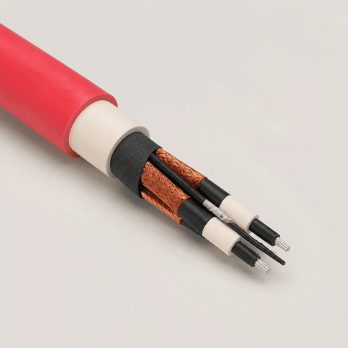
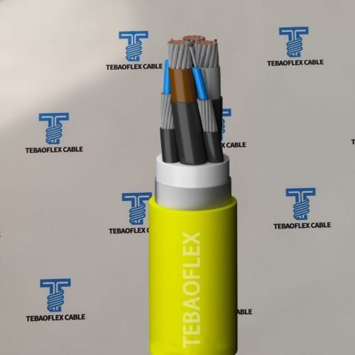
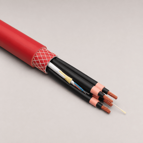
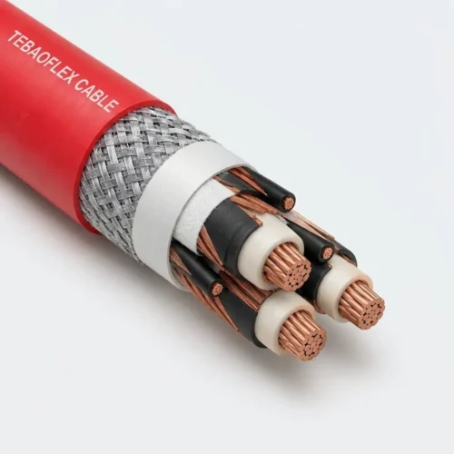
Type 245 centers three extensible EPR-covered pilot cores inside a cushioned semiconductive PCP cradle, surrounded by three semiconductive-screened EPR phase cores, three interstitial earth conductors, open-weave reinforcement, and a heavy-duty PCP sheath.
| Layer / Component | Material & AS/NZS 1802 Specification |
|---|---|
| 1. Phase Conductors | Flexible finely stranded tinned annealed copper, three phase cores (0.30–0.40 mm wires; up to 2,146 strands on 150 mm²) |
| 2. Conductor Screen | Extruded semi-conductive compound for cables rated 3.3 kV (Type 245.3) and 6.6 kV (Type 245.6) |
| 3. Insulation & Screen | R-EP-90 EPR thermosetting insulation enclosed in an extruded semi-conductive elastomer insulation screen |
| 4. Three Central Pilots | Three central extensible pilots laid at the cable center inside a semiconductive PCP cradle separator (each 28/0.25 mm tinned Cu with 0.8 mm EPR cover) |
| 5. Interstitial Earths & Fill | Three semiconductive-PCP-covered flexible tinned copper earth cores (69/0.25 to 375/0.30) + semiconductive PCP overall core filling & covering |
| 6. Reinforcement & Sheath | Open-weave reinforcing yarns embedded beneath a black heavy-duty HD-85-PCP outer sheath (CPE/CSP sheath available on request) |
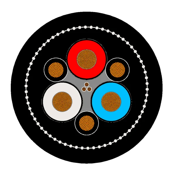
Type 245 Cross-Section Geometry: Note the distinctive trefoil bundle of three central extensible pilots cushioned inside the grey semiconductive PCP cradle between the three phase cores.
Technical Characteristics
Manufactured to AS/NZS 1802 across 1.1 kV, 3.3 kV, and 6.6 kV, Type 245 longwall shearer cables provide +90 °C continuous thermal rating, −25 °C cold bend capability, and C1 vertical flame retardancy.
| Parameter | AS/NZS 1802 Rated Value |
|---|---|
| Manufacturing Standard | AS/NZS 1802 (Electric cables — Reeling and trailing — For underground coal mining applications) |
| Voltage Grades & Sub-Types | Type 245.1 (1.1/1.1 kV) | Type 245.3 (3.3/3.3 kV) | Type 245.6 (6.6/6.6 kV) |
| Phase Cross-Section Range | 16–150 mm² (1.1 kV) | 25–150 mm² (3.3 kV) | 50–150 mm² (6.6 kV) |
| Central Pilot Configuration | 3 × extensible central pilots (28/0.25 mm tinned copper, 0.8 mm EPR insulation) |
| Max. Continuous Conductor Temp. | +90 °C |
| Minimum Installation Temperature | −25 °C |
| Primary Service Conditions | Longwall shearer, continuous miner, and peripheral longwall face cable service |
| Sheath Colour & Flame Rating | Black HD-85-PCP standard (custom colours / CPE / CSP on request) | C1 flame performance |
Specification & Stranding Data (20 Standard Sizes)
Dimensional, wire stranding, insulation/sheath wall, and mass specifications for AS/NZS 1802 Type 245.1 (1.1 kV), Type 245.3 (3.3 kV), and Type 245.6 (6.6 kV) longwall shearer cables.
| Sub-Type | Voltage | Area Range | Phase Strand | EPR Insul. | OD Range | Mass (kg/100m) |
|---|---|---|---|---|---|---|
| Type 245.1 | 1.1/1.1 kV | 16–150 mm² (8) | 133/0.40 – 2146/0.30 | 1.6–2.3 mm | 42.6–70.5 mm | 235–915 |
| Type 245.3 | 3.3/3.3 kV | 25–150 mm² (7) | 259/0.36 – 2146/0.30 | 3.0 mm | 51.1–75.2 mm | 338–1028 |
| Type 245.6 | 6.6/6.6 kV | 50–150 mm² (5) | 703/0.30 – 2146/0.30 | 5.0 mm | 67.2–85.8 mm | 635–1210 |
Type 245.1 — Rated Voltage: 1.1/1.1 kV (16 mm² to 150 mm² | 8 Sizes)
| Area (mm²) | Phase Strand (No./mm) | Insul. (mm) | Earth Strand (No./mm) | Screen / Cover (mm) | Pilot Strand (3×) | Pilot Cover (mm) | Sheath (mm) | Cable Dia. (mm) | Mass (kg/100m) |
|---|---|---|---|---|---|---|---|---|---|
| 3 × 16 | 133 / 0.40 | 2.0 | 69 / 0.25 | 1.8 | 28 / 0.25 | 0.8 | 4.1 | 42.6 | 235 |
| 3 × 25 | 259 / 0.36 | 1.6 | 91 / 0.25 | 1.8 | 28 / 0.25 | 0.8 | 4.2 | 43.4 | 269 |
| 3 × 35 | 287 / 0.40 | 1.6 | 140 / 0.25 | 1.4 | 28 / 0.25 | 0.8 | 4.4 | 45.6 | 315 |
| 3 × 50 | 703 / 0.30 | 1.7 | 120 / 0.30 | 1.0 | 28 / 0.25 | 0.8 | 4.8 | 48.4 | 390 |
| 3 × 70 | 988 / 0.30 | 1.8 | 180 / 0.30 | 1.0 | 28 / 0.25 | 0.8 | 5.1 | 53.9 | 501 |
| 3 × 95 | 1332 / 0.30 | 2.0 | 150 / 0.30 | 1.0 | 28 / 0.25 | 0.8 | 5.6 | 60.4 | 630 |
| 3 × 120 | 1702 / 0.30 | 2.1 | 195 / 0.30 | 1.2 | 28 / 0.25 | 0.8 | 6.0 | 65.5 | 765 |
| 3 × 150 | 2146 / 0.30 | 2.3 | 235 / 0.30 | 1.2 | 28 / 0.25 | 0.8 | 6.3 | 70.5 | 915 |
Type 245.3 — Rated Voltage: 3.3/3.3 kV (25 mm² to 150 mm² | 7 Sizes)
| Area (mm²) | Phase Strand (No./mm) | Insul. (mm) | Earth Strand (No./mm) | Screen / Cover (mm) | Pilot Strand (3×) | Pilot Cover (mm) | Sheath (mm) | Cable Dia. (mm) | Mass (kg/100m) |
|---|---|---|---|---|---|---|---|---|---|
| 3 × 25 | 259 / 0.36 | 3.0 | 91 / 0.25 | 1.5 | 28 / 0.25 | 0.8 | 5.2 | 51.1 | 338 |
| 3 × 35 | 287 / 0.40 | 3.0 | 140 / 0.25 | 1.0 | 28 / 0.25 | 0.8 | 5.4 | 54.5 | 398 |
| 3 × 50 | 703 / 0.30 | 3.0 | 120 / 0.30 | 1.0 | 28 / 0.25 | 0.8 | 5.7 | 56.8 | 490 |
| 3 × 70 | 988 / 0.30 | 3.0 | 180 / 0.30 | 1.2 | 28 / 0.25 | 0.8 | 6.0 | 61.2 | 592 |
| 3 × 95 | 1332 / 0.30 | 3.0 | 235 / 0.30 | 1.2 | 28 / 0.25 | 0.8 | 6.4 | 66.6 | 739 |
| 3 × 120 | 1702 / 0.30 | 3.0 | 300 / 0.30 | 1.2 | 28 / 0.25 | 0.8 | 6.7 | 71.0 | 870 |
| 3 × 150 | 2146 / 0.30 | 3.0 | 375 / 0.30 | 1.2 | 28 / 0.25 | 0.8 | 7.0 | 75.2 | 1028 |
Type 245.6 — Rated Voltage: 6.6/6.6 kV (50 mm² to 150 mm² | 5 Sizes)
| Area (mm²) | Phase Strand (No./mm) | Insul. (mm) | Earth Strand (No./mm) | Screen / Cover (mm) | Pilot Strand (3×) | Pilot Cover (mm) | Sheath (mm) | Cable Dia. (mm) | Mass (kg/100m) |
|---|---|---|---|---|---|---|---|---|---|
| 3 × 50 | 703 / 0.30 | 5.0 | 120 / 0.30 | 1.4 | 28 / 0.25 | 0.8 | 6.7 | 67.2 | 635 |
| 3 × 70 | 988 / 0.30 | 5.0 | 180 / 0.30 | 1.4 | 28 / 0.25 | 0.8 | 7.0 | 71.7 | 755 |
| 3 × 95 | 1332 / 0.30 | 5.0 | 235 / 0.30 | 1.4 | 28 / 0.25 | 0.8 | 7.4 | 77.1 | 905 |
| 3 × 120 | 1702 / 0.30 | 5.0 | 300 / 0.30 | 1.4 | 28 / 0.25 | 0.8 | 7.7 | 81.3 | 1050 |
| 3 × 150 | 2146 / 0.30 | 5.0 | 375 / 0.30 | 1.4 | 28 / 0.25 | 0.8 | 8.0 | 85.8 | 1210 |
Selection: Type 245 vs. Type 245UF vs. Type 241
Selecting between AS/NZS 1802 semiconductive screened cables depends on pilot-core count (3 central pilots vs. 1 central pilot), system voltage (up to 6.6 kV vs. 3.3 kV), and shearer cable-chain bend radius.
| Cable Model | Key Architecture & Best-Fit Longwall Duty |
|---|---|
| Type 245 (This Product) | 3 central extensible pilots, 16–150 mm², rated across 1.1 kV, 3.3 kV, and 6.6 kV. Ideal for high-voltage 6.6 kV shearers, continuous miners, and peripheral longwall drives needing multi-channel control/monitoring. |
| Type 245UF (Ultra-Flexible) | Type 245UF covers 50–150 mm² at 1.1 kV & 3.3 kV with ultra-flexible lay geometry and ≤3 Ω/100m central pilots specifically optimized for tight articulated Bretby shearer cable handler chains. |
| Type 241 / Type 241SF | Where only a single central extensible pilot is required (up to 11/11 kV and 300 mm²), specify Type 241 or narrow-loop monorail Type 241SF. |
Frequently Asked Questions (FAQ)
Technical answers covering Type 245 three-pilot geometry, 6.6 kV longwall shearer supply, and outer sheath compounds.
Why are the three pilots placed in the center of Type 245 rather than in the outer interstices?
On a reciprocating longwall shearer, the three outer interstices are occupied by large semiconductive-covered earth conductors in continuous fault-sensing contact with the phase screens. Grouping the three extensible control/monitoring pilots along the neutral center axis inside a semiconductive PCP cradle shields them from external crush loads and minimizes tensile strain during cyclic bending.
Does Type 245 support 6.6 kV high-output longwall shearers?
Yes. Type 245.6 (6.6/6.6 kV) is manufactured from 50 mm² to 150 mm² with extruded conductor screens, 5.0 mm R-EP-90 EPR insulation, semiconductive elastomer screens, and 6.7–8.0 mm reinforced HD-85-PCP sheathing for high-voltage longwall faces.
Can TEBAOFLEX manufacture Type 245 with high-visibility coloured or CPE/CSP sheaths?
Yes. Black HD-85-PCP is supplied as standard, and we custom-extrude CPE, CSP, or mine-specified visibility stripes/colours cut to exact longwall face lengths on export drums.
Request a Factory Quote for AS/NZS 1802 Type 245 Shearer Cables
Share your longwall face voltage (1.1 kV, 3.3 kV, or 6.6 kV), cross-section (16–150 mm²), and required cut length with TEBAOFLEX engineering sales.
Explore All Mining & Tunneling Cables