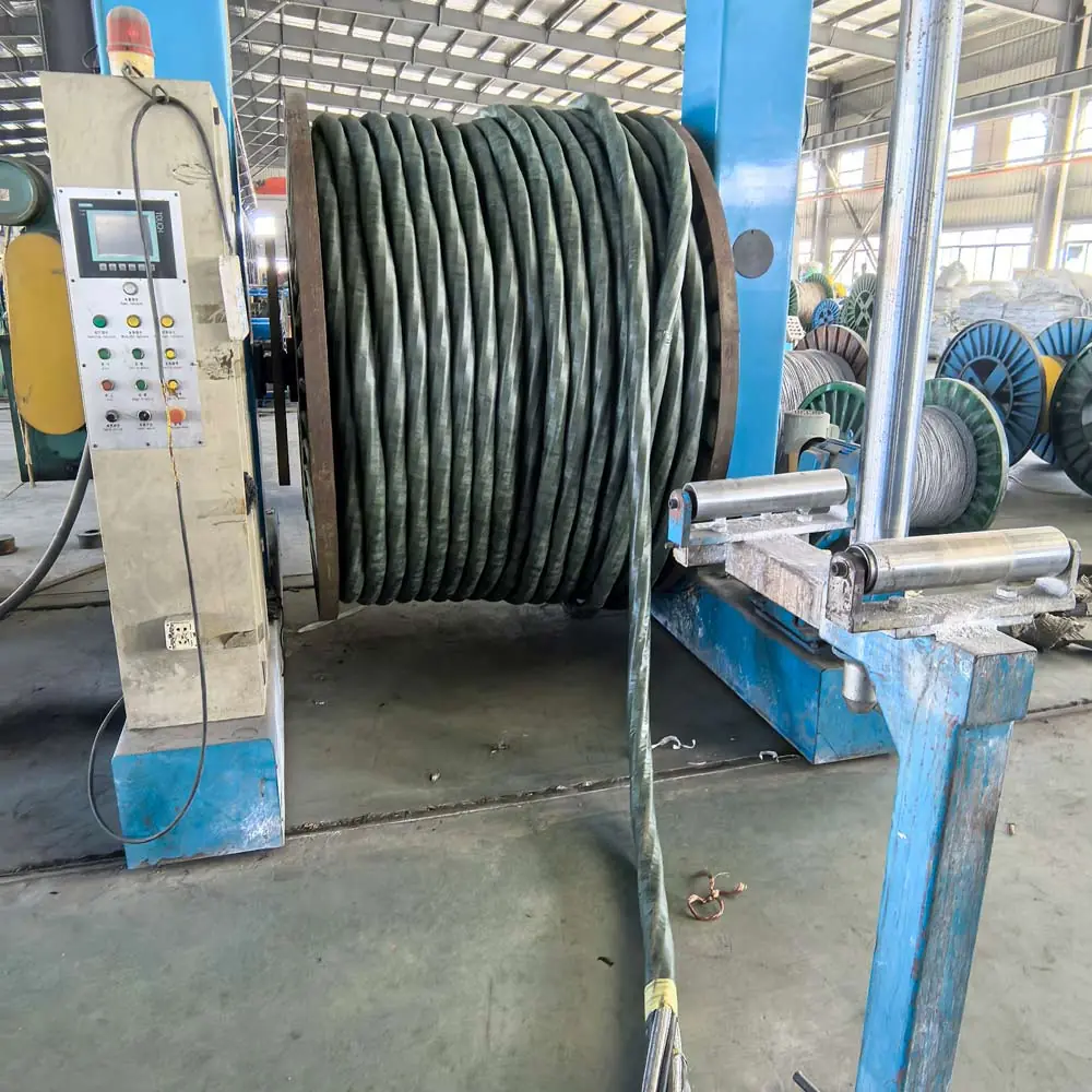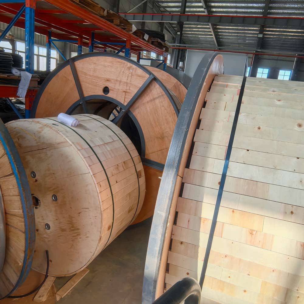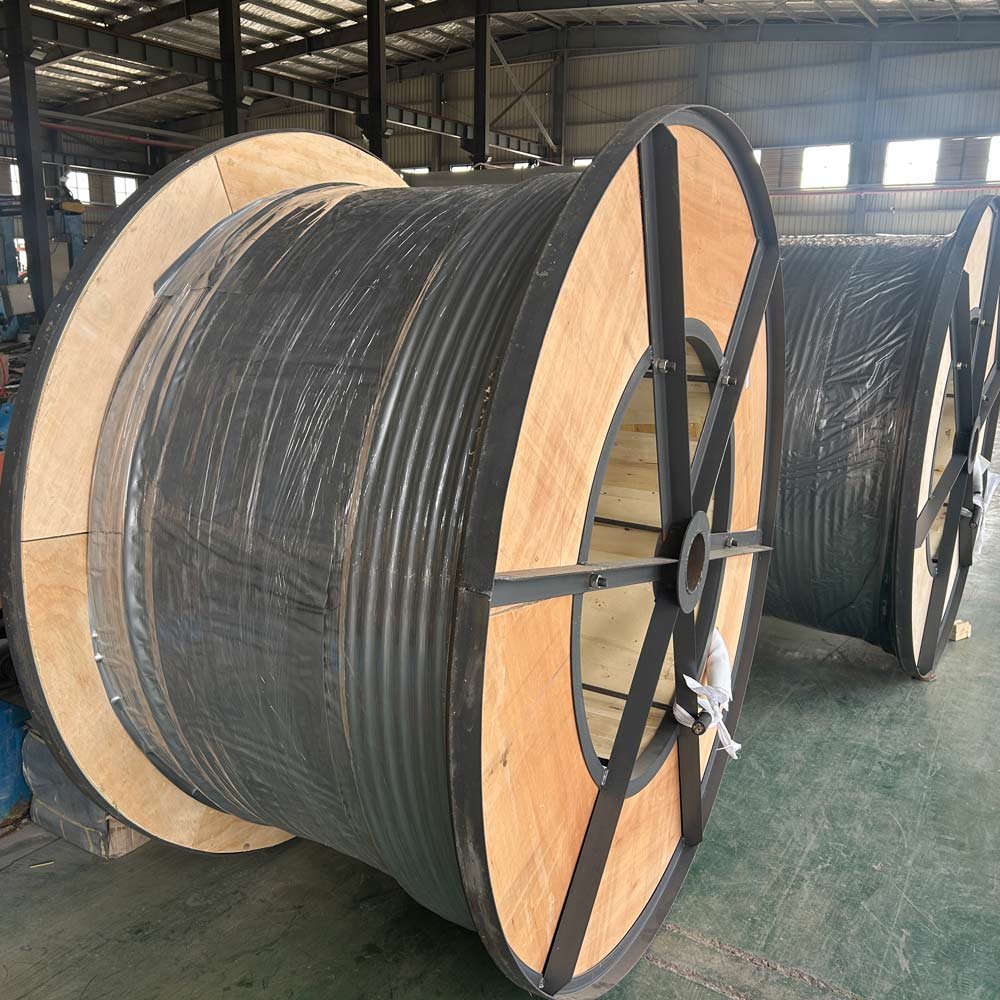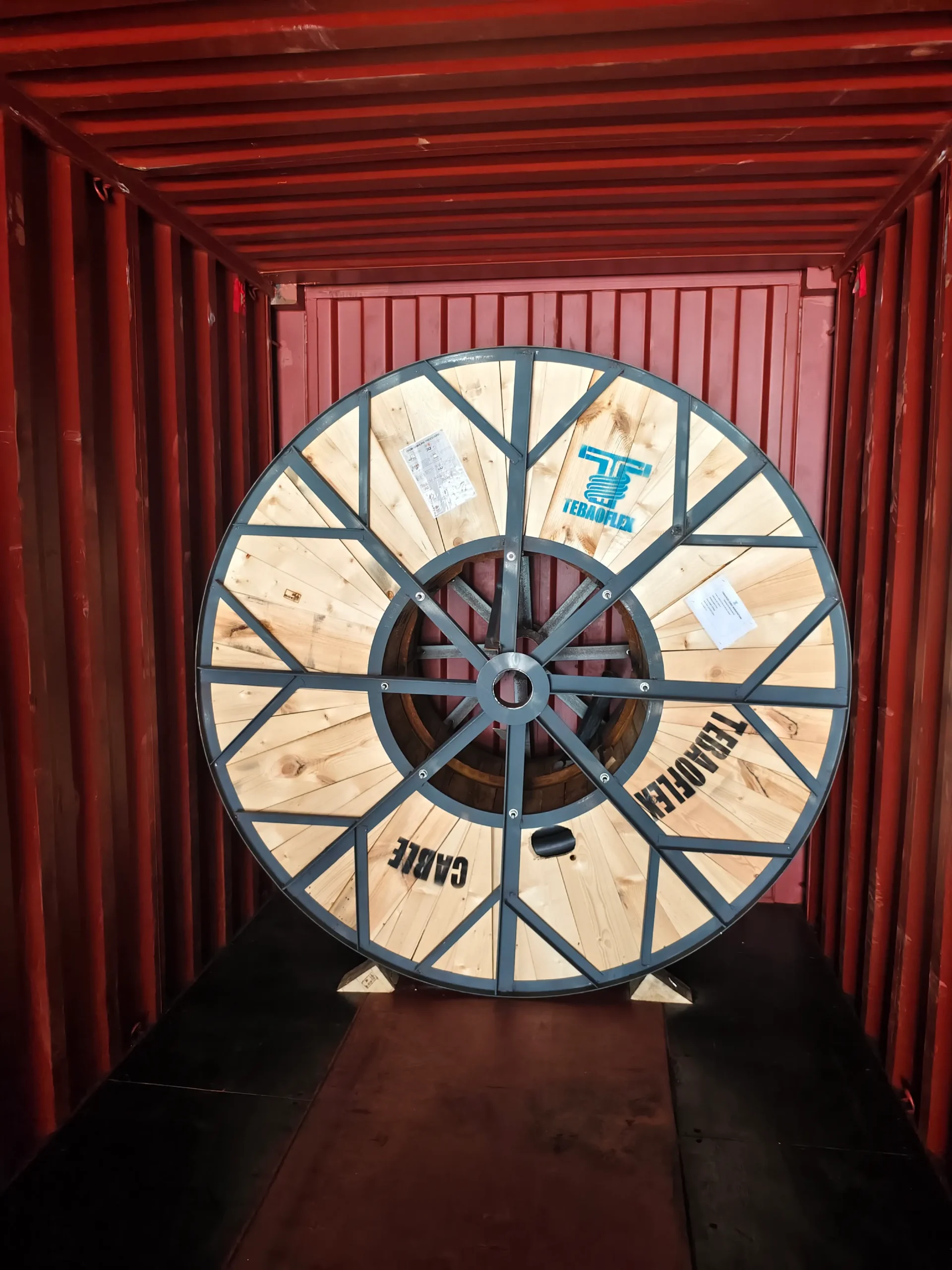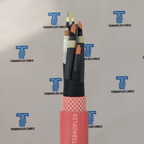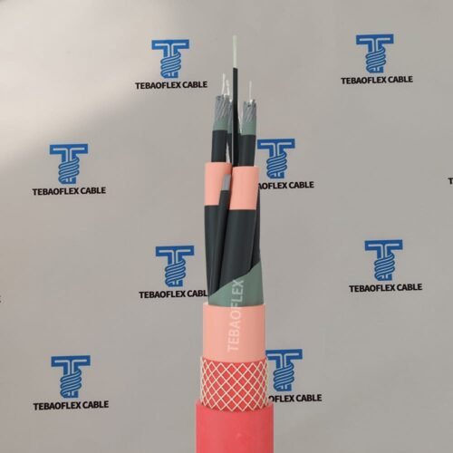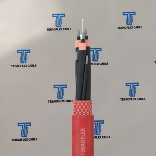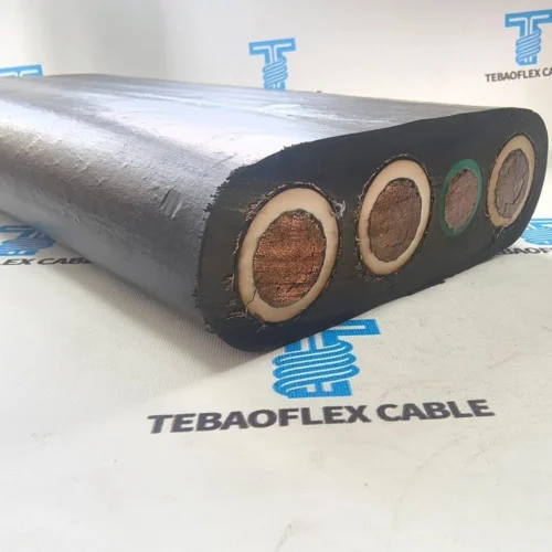
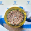
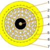
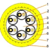

(N)SHTÖU-O/J 0.6/1 kV reeling cable is a heavy-duty rubber cable range for gantry reels, trolley festoon systems, mining equipment and mobile machinery exposed to repeated bending, torsion and tensile load. The J range covers power, control, combined-control and fibre-optic configurations, while the O range includes bus cable designs.
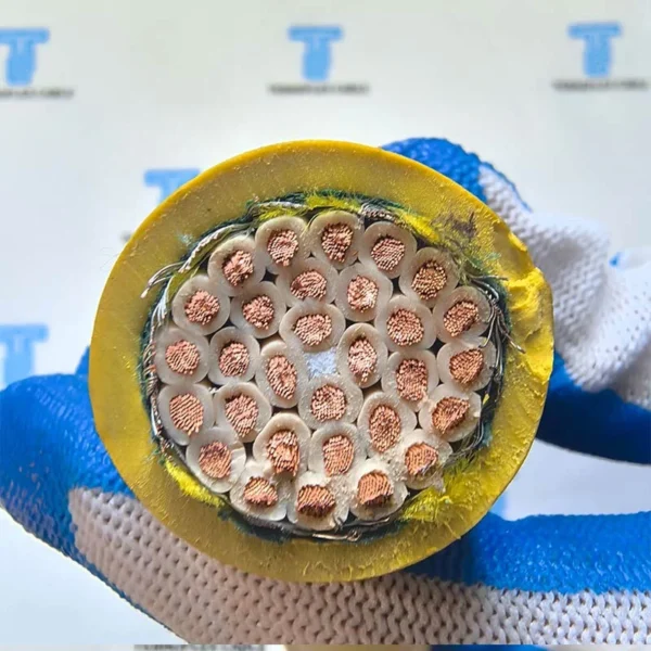
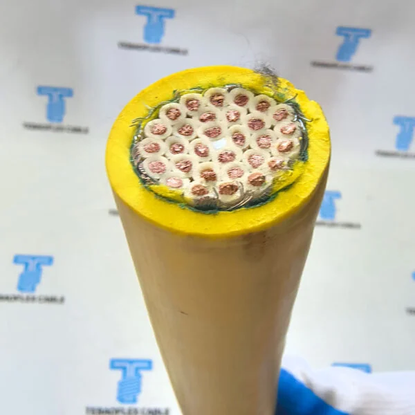
Very finely stranded tinned copper conductors, EPR-based core insulation, PCP-based inner and outer sheaths and a reinforced polyester anti-torsion braid create a flexible cable system for high and very high mechanical stress. TEBAOFLEX can review the conductor arrangement, bus or fibre elements, travel speed, bending path and cable length as one engineered configuration.
(N)SHTÖU-O/J Cable at a Glance
| Selection point | Specification |
|---|---|
| Cable type | (N)SHTÖU-O/J heavy-duty low-voltage reeling cable |
| Rated voltage | 0.6/1 kV (600/1000 V) |
| J configurations | Power, control, combined-control and fibre-optic control cables |
| O configurations | Bus cable configurations |
| Conductor | Very finely stranded electrolytic tinned copper, Class FS |
| Core insulation | EPR-based special rubber compound, minimum 3GI3 |
| Sheath system | Yellow PCP-based inner and outer sheaths with reinforced anti-torsion braid |
| Main applications | Gantry reels, trolley festoons, mining machines and heavy mobile handling equipment |
What Is the Difference Between (N)SHTÖU-J and (N)SHTÖU-O?
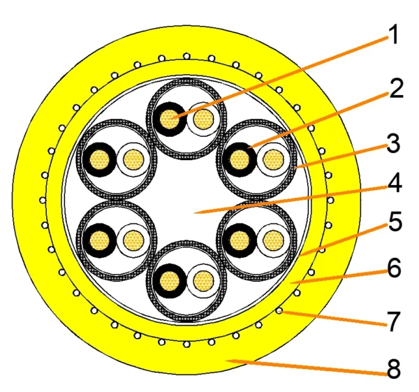
Within this product range, (N)SHTÖU-J identifies the power and control cable configurations, including combined control and fibre-optic versions. (N)SHTÖU-O identifies the listed bus cable configurations. This distinction matters because power cores, screened pairs, bus elements and optical fibres require different internal layouts even when they share the same heavy-duty reeling sheath system.
Searches may omit the umlaut and appear as NSHTOEU-J cable, NSHTOEU-O cable or NSHTOEU reeling cable. These spellings refer to the same product designation family, but the ordered configuration must always state the complete core and cross-section arrangement.
Cable Construction
| Construction element | Specification | Function |
|---|---|---|
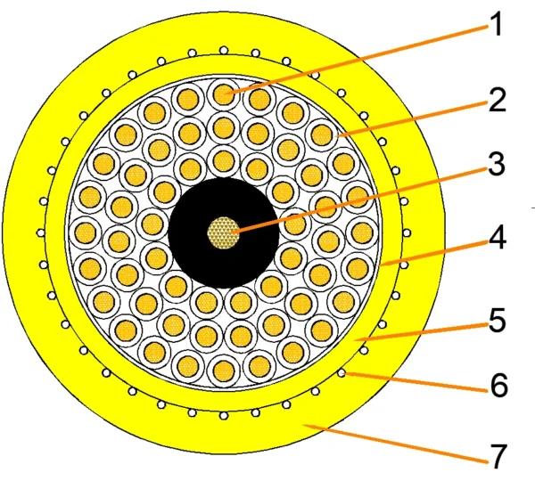
| Conductor | Electrolytic tinned copper, very finely stranded, Class FS | Supports repeated movement and flexible routing. |
| Insulation | EPR-based special rubber compound, minimum 3GI3 | Electrical insulation for power and control cores. |
| Core identification | Light-coloured insulation with black printed numbers; green-yellow earth conductor where specified | Clear circuit identification during termination and maintenance. |
| Individual screen | Tinned copper wire braid for screened cores or twisted screened pairs | At least 60% coverage for screened cores and at least 80% for twisted screened pairs. |
| Core arrangement | Laid up in a maximum of three layers | Balances flexibility, cable diameter and internal stability. |
| Inner sheath | Yellow high-grade PCP-based special rubber compound | Supports the laid-up core assembly. |
| Anti-torsion reinforcement | Reinforced polyester-thread braid in a vulcanised bond between the sheaths | Helps control twisting and mechanical stress during travel. |
| Outer sheath | Yellow abrasion- and tear-resistant PCP-based special rubber compound | Provides the external mechanical and environmental protection. |
Electrical, Thermal and Mechanical Data
| Parameter | Value |
|---|---|
| Rated voltage | 0.6/1 kV |
| Maximum permissible operating voltage, AC | 0.7/1.2 kV |
| Maximum permissible operating voltage, DC | 0.9/1.8 kV |
| AC test voltage | 3.5 kV for 5 minutes |
| Maximum conductor temperature | 90°C |
| Maximum short-circuit conductor temperature | 250°C |
| Fixed-installation ambient temperature | -50°C to +80°C |
| Fully flexible operating ambient temperature | -35°C to +80°C |
| Maximum tensile load on conductor | 30 N/mm² |
| Torsional stress | ±50°/m |
| Minimum bending radius | According to DIN VDE 0298 Part 3 for the selected installation |
| Minimum distance with S-type directional changes | 20 × cable diameter (D) |
| Gantry reeling speed | No stated restriction; consult TEBAOFLEX for speeds above 240 m/min |
| Trolley festoon speed | Up to 240 m/min |
| Additional dynamic tests | Reversed bending, roller bending and torsional stress tests |
Environmental and Transmission Options
The referenced construction is intended for indoor and outdoor operation and is specified for resistance to ozone, UV exposure and moisture. Water resistance is evaluated through long-term testing. Oil resistance is specified according to DIN EN 60811-404 and DIN VDE 0473-811-404, Paragraph 10. Final suitability depends on the ordered compound, installation and exposure conditions.
Where required, the reeling cable can integrate AS-Interface, PROFIBUS, CAN bus or Industrial Ethernet elements. Fibre-optic elements can also be included for data transmission. State the protocol, impedance or optical-fibre specification with the power and control requirements.
3-Core Power Cable Sizes
| Configuration | OD range (mm) | Free-moving bend radius (mm) | Approx. weight (kg/km) | Max. tensile force (N) | Resistance at 20°C (Ω/km) | Current capacity (A) |
|---|---|---|---|---|---|---|
| 3 × 35 + 3 × 16/3 | 28.7–31.7 | 159 | 1,990 | 3,150 | 0.57 | 162 |
| 3 × 50 + 3 × 25/3 | 34.4–37.4 | 187 | 2,810 | 4,500 | 0.39 | 202 |
| 3 × 70 + 3 × 35/3 | 39.7–42.7 | 214 | 3,860 | 6,300 | 0.28 | 250 |
| 3 × 95 + 3 × 50/3 | 44.3–47.3 | 237 | 4,950 | 8,550 | 0.21 | 301 |
| 3 × 120 + 3 × 70/3 | 51.0–55.0 | 275 | 6,440 | 10,800 | 0.16 | 352 |
| 3 × 150 + 3 × 70/3 | 53.9–57.9 | 290 | 7,500 | 13,500 | 0.13 | 404 |
| 3 × 185 + 3 × 95/3 | 58.9–62.9 | 315 | 8,990 | 16,650 | 0.11 | 461 |
| 3 × 240 + 3 × 120/3 | 67.4–71.4 | 357 | 11,940 | 21,600 | 0.08 | 540 |
| 3 × 300 + 3 × 150/3 | 75.6–79.6 | 398 | 14,740 | 27,000 | 0.07 | 620 |
4-Core and 5-Core Power Cable Sizes
| Configuration | OD range (mm) | Free-moving bend radius (mm) | Approx. weight (kg/km) | Max. tensile force (N) | Resistance at 20°C (Ω/km) | Current capacity (A) |
|---|---|---|---|---|---|---|
| 4 × 4 | 16.0–18.0 | 90 | 450 | 480 | 5.09 | 41 |
| 4 × 6 | 17.4–19.4 | 97 | 600 | 720 | 3.39 | 53 |
| 4 × 10 | 21.6–23.6 | 118 | 900 | 1,200 | 1.95 | 74 |
| 4 × 16 | 23.7–26.7 | 134 | 1,240 | 1,920 | 1.24 | 99 |
| 4 × 25 | 28.5–31.5 | 158 | 1,850 | 3,000 | 0.80 | 131 |
| 5 × 4 | 17.4–19.4 | 97 | 550 | 600 | 5.09 | 41 |
| 5 × 6 | 19.0–21.0 | 105 | 690 | 900 | 3.39 | 53 |
| 5 × 10 | 23.4–25.4 | 127 | 1,070 | 1,500 | 1.95 | 74 |
| 5 × 16 | 26.1–29.1 | 146 | 1,500 | 2,400 | 1.24 | 99 |
| 5 × 25 | 33.7–36.7 | 184 | 2,340 | 3,750 | 0.80 | 131 |
Control, Bus and Composite Configurations
| Cable family | Available configurations | Reference electrical data | Reference OD range |
|---|---|---|---|
| 1.5 mm² control cable | 3, 4, 5, 7, 12, 18, 24, 30, 36, 44 or 56 cores | 13.7 Ω/km; 23 A | 11.7–38.9 mm across listed sizes |
| 2.5 mm² control cable | 3, 4, 5, 7, 12, 18, 24, 30, 36, 44 or 56 cores | 8.21 Ω/km; 30 A | 12.7–43.1 mm across listed sizes |
| Bus cable | 6 × (2 × 0.5)C; 3, 6 or 9 × (2 × 1)C; 12 × (2 × 1)C; 12 × 1(C) | 40.1 Ω/km for 0.5 mm²; 20.0 Ω/km for 1 mm² | 22.0–42.3 mm across listed sizes |
| Combined control cable | 12 × 2.5 + 12 × 1(C); 19 × 2.5 + 5 × 1(C); 19 × 2.5 + 5 × 1.5(C); 25 × 2.5 + 5 × 1(C) | 8.21 Ω/km on the 2.5 mm² power/control conductors | 26.2–34.0 mm across listed sizes |
| Fibre-optic control cable | Power/control cores with G62.5, G50 or E9 optical-fibre elements | Electrical data follows the selected 1.5 or 2.5 mm² conductor group | 26.5–33.3 mm across listed sizes |
Current-carrying values are nominal references for rubber cables laid on a surface at 30°C ambient temperature using DIN VDE 0298-4, Table 15. Installation-specific current capacity must be checked for the actual routing, grouping, reel condition and ambient temperature.
Typical Applications
- Gantry crane and cable-drum reeling systems.
- Trolley festoon systems operating at high travel speed.
- Open-cast and underground mining equipment.
- Stacker-reclaimers, mobile conveyors and material-handling machinery.
- Moving equipment requiring power, control, bus communication or fibre-optic transmission in one cable family.
How to Specify an NSHTOEU Reeling Cable
| RFQ input | Why it matters |
|---|---|
| J or O configuration | Defines whether the cable is a power/control/fibre design or a bus configuration. |
| Core count and cross-section | Sets current capacity, resistance, diameter, weight and tensile limit. |
| Reel or festoon arrangement | Determines bending path, S-bends, travel length and dynamic duty. |
| Travel speed and acceleration | Needed to review mechanical loading and high-speed operation. |
| Tensile and torsional demand | Confirms whether the selected reinforcement and installation remain within limits. |
| Ambient and exposure | Defines temperature, UV, ozone, water, oil and outdoor requirements. |
| Data protocol or fibre type | Required for AS-Interface, PROFIBUS, CAN bus, Industrial Ethernet or optical elements. |
| Cable length and termination | Supports voltage-drop review, drum capacity, connectors and delivery planning. |
Installation Limits
- Do not select a reeling cable from voltage and cross-section alone; dynamic path, reel geometry, speed, tension and torsion must be reviewed together.
- Maintain the specified bending radius and at least 20 × D separation for S-type directional changes.
- For gantry speeds above 240 m/min, provide the complete motion profile for engineering review.
- Current capacity must be corrected for installation method, ambient temperature, grouping and operation on a drum.
- Protect the cable from crushing, uncontrolled sidewall pressure, sharp guide edges and unsuitable reel tension.
Related Reeling Cable Options
- (N)SHT11Y PUR vertical reeling cable for port cranes
- GPM-RF heavy-duty PUR reeling cable
- Heavy-duty PCP reeling cable for motorised reels
Frequently Asked Questions
What is an NSHTOEU-J cable?
It is the search spelling commonly used for an (N)SHTÖU-J 0.6/1 kV heavy-duty rubber reeling cable. The J range includes power, control, combined-control and fibre-optic configurations for moving machinery.
Where is (N)SHTÖU-O/J cable used?
Typical uses include gantry reels, trolley festoons, mining equipment, stacker-reclaimers and other mobile machinery exposed to repeated bending, torsion and pulling loads.
What is the maximum operating speed?
The listed trolley festoon speed is up to 240 m/min. Gantry reeling has no stated restriction, but installations above 240 m/min require project-specific consultation.
Can this reeling cable carry bus or fibre-optic signals?
Yes. The range can include AS-Interface, PROFIBUS, CAN bus, Industrial Ethernet or fibre-optic elements when the protocol and internal arrangement are specified.
Is the cable suitable for outdoor and wet environments?
The referenced construction is specified for indoor and outdoor use with ozone, UV and moisture resistance, including long-term water-resistance testing. The exact exposure and ordered compound must still be confirmed.
What information is required for a quotation?
Provide the full configuration, cross-section, reel or festoon layout, travel length, speed, acceleration, bending path, tensile demand, ambient conditions, communication elements, cable length and quantity.
Send Your Reeling Cable Requirements
Send the required power, control, bus or fibre-optic configuration together with the motion and installation data. TEBAOFLEX will review the conductor arrangement, dimensions and dynamic duty before quotation.