

2PNCT-H-U 600V RTG Reeling Cable
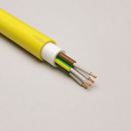
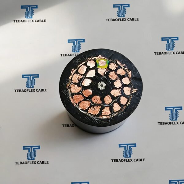
The 2PNCT-H-U 600V RTG reeling cable in the listed 30 × 3.5 mm² configuration is intended for moving electrical connections in RTG crane baloney arrangements, motor-driven reeling drums, cable-chain systems and lift systems. It combines flexible tinned annealed copper conductors, EPR insulation, a central U-type stainless-steel reinforcement and a black polychloroprene rubber sheath.
Unlike a fixed-installation cable, a reeling cable must be selected around the actual drum, route, travel distance, movement speed, tensile load and surrounding conditions. Therefore, the values on this page are a supplied construction reference; the final design should be reviewed against the specific reeling system.
Product Overview & Key Advantages
The 2PNCT-H-U 600V 30 × 3.5 mm² reeling cable is designed for moving electrical connections in RTG crane baloney arrangements, motor-driven cable reels, cable-chain systems and lift systems. Its 30-core configuration provides a compact route where multiple power and control connections need to travel together through a managed reeling system. For RTG and industrial equipment, this helps project teams evaluate one supplied cable construction against the movement, routing and connection requirements of the installation.
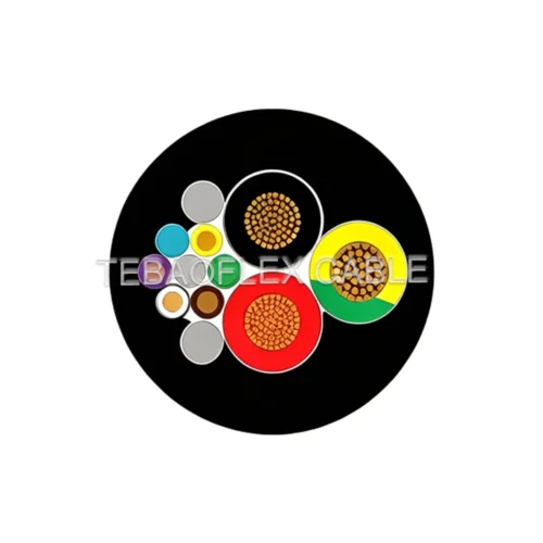
The supplied construction combines flexible tinned annealed copper conductors, EPR insulation, tape layers, a U-type rubber-insulated stainless-steel centre reinforcement and a black polychloroprene rubber outer sheath. The centre reinforcement is identified in the supplied construction for reeling duty. It should be assessed with the actual pulling force, drum arrangement and route geometry rather than treated as a universal solution for every moving installation.
For the listed 30 × 3.5 mm² configuration, the supplied reference gives a standard overall diameter of 39.9 mm, a maximum overall diameter of 41.9 mm and a maximum permissible tensile force of 2.9 kN. The specified minimum bending radius is 7.5 times the overall cable diameter. Together, these values help engineering teams compare the cable with drum dimensions, routing clearances and movement requirements before final selection.
Current capacity should be considered with the ambient temperature, core count, cable grouping and reeling conditions. Therefore, conductor size alone is not sufficient for final selection. Providing the drum diameter, travel distance, reeling speed, cable length, maximum pulling force and installation environment allows TEBAOFLEX to review whether the supplied construction is suitable for the project. For additional planning guidance, see our RTG reeling cable selection guide.
Selection Advantages
- Multi-core integration: the listed 30-core arrangement supports combined moving power and control connections in one cable route.
- Reeling-oriented construction: EPR insulation, a polychloroprene rubber sheath and U-type stainless-steel centre reinforcement are identified in the supplied construction.
- Selection-ready data: the page lists 600 V rating, 3 kV / 1 minute test voltage, 7.5 × D minimum bending radius, 2.9 kN maximum permissible tensile force and 4,900 N/m maximum lateral pressure.
- Project-specific review: drum dimensions, tension, movement speed and installation conditions remain essential inputs before final confirmation.
Construction and Materials
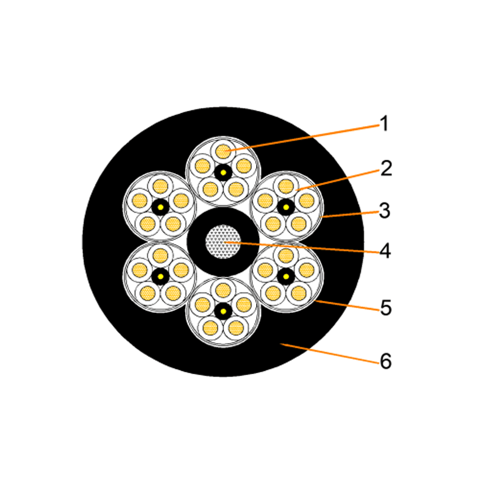
| Component | Supplied construction |
|---|---|
| Conductor | Flexible tinned annealed copper |
| Insulation | EPR (ethylene-propylene rubber) compound |
| Centre reinforcement | U-type stainless-steel wires with rubber insulation |
| Assembly layers | Tape layers around the cable assembly |
| Outer sheath | Black polychloroprene rubber compound |
| Standard reference | JIS C 3327, as listed in the supplied specification |
30 × 3.5 mm² Technical Data
| Parameter | Listed value |
|---|---|
| Rated voltage | AC 600 V |
| Test voltage | 3,000 V for 1 minute |
| Temperature range | -15 °C to +80 °C |
| Minimum bending radius | 7.5 × overall cable diameter |
| Maximum lateral pressure | 4,900 N/m |
| Nominal conductor diameter | 2.5 mm |
| Standard overall diameter | 39.9 mm |
| Maximum overall diameter | 41.9 mm |
| Approximate net weight | 2,480 kg/km |
| Maximum conductor resistance | 6.22 Ω/km |
| Maximum permissible tensile force | 2.9 kN |
The 2PNCT-H-U family can be supplied in configurations up to 49 cores, subject to the selected construction. The 30 × 3.5 mm² data above applies to this listed configuration and should not be used as a substitute for a project-specific cable calculation.
Available 2PNCT-H-U 3.5 mm² Configurations
| Cores × cross-section | Std. OD | Max. OD | Approx. weight | Max. tensile force |
|---|---|---|---|---|
| 12 × 3.5 mm² | 25.9 mm | 27.2 mm | 1,000 kg/km | 1.1 kN |
| 16 × 3.5 mm² | 29.0 mm | 30.5 mm | 1,310 kg/km | 1.5 kN |
| 20 × 3.5 mm² | 32.4 mm | 34.0 mm | 1,620 kg/km | 1.9 kN |
| 24 × 3.5 mm² | 35.8 mm | 37.6 mm | 1,970 kg/km | 2.3 kN |
| 30 × 3.5 mm² | 39.9 mm | 41.9 mm | 2,480 kg/km | 2.9 kN |
| 36 × 3.5 mm² | 44.1 mm | 46.4 mm | 3,050 kg/km | 3.5 kN |
| 42 × 3.5 mm² | 49.3 mm | 51.8 mm | 3,880 kg/km | 4.1 kN |
| 49 × 3.5 mm² | 54.2 mm | 56.9 mm | 4,560 kg/km | 4.8 kN |
Current-Carrying Selection Notes
Do not select a reeling cable by conductor size alone. The supplied reference states that permissible current must be corrected for ambient temperature, multiple-cable installation, reeling duty and core count. The following ambient-temperature factors are a selection aid only; the base current and final correction for the actual reeling route must be confirmed for the project.
| Ambient temperature | Correction factor |
|---|---|
| 30 °C | 1.00 |
| 35 °C | 0.95 |
| 40 °C | 0.89 |
| 45 °C | 0.84 |
| 50 °C | 0.77 |
| 55 °C | 0.71 |
| 60 °C | 0.63 |
| 65 °C | 0.55 |
| 70 °C | 0.45 |
| 75 °C | 0.31 |
Applications and Project Inputs
Typical supplied applications include RTG crane baloney arrangements, motor-driven cable reels, cable-chain systems, lift systems and industrial moving equipment. For an accurate construction review, provide the operating voltage, core count, conductor size, cable length, travel distance, reeling speed, drum dimensions, maximum pulling force and ambient conditions. These inputs help distinguish a suitable reeling construction from a cable intended only for fixed or low-movement installation.
Related constructions can be explored in our Port, Crane & Festoon Cables and Rubber & Flexible Cables categories.
Frequently Asked Questions
What is the primary function of a baloney cable in RTG crane operations?
In many port and crane projects, “baloney cable” is an informal name for a flexible reeling cable that carries moving electrical connections between the cable reel and RTG equipment. The exact construction should be selected for the project’s voltage, core count, movement and mechanical conditions.
Does 2PNCT-H-U cable include an anti-torsion textile braid?
The supplied 2PNCT-H-U specification identifies a U-type rubber-insulated stainless-steel centre reinforcement. It does not identify an anti-torsion textile braid between inner and outer sheaths. Any additional anti-torsion construction should be confirmed in the final project specification.
Which data is required to select the 30 × 3.5 mm² cable?
Confirm voltage, cable length, drum diameter, travel distance, reeling speed, maximum pulling force, ambient conditions and the required core functions before final construction review.
Can the listed current value be used directly for every installation?
No. Ambient temperature, core count, grouping and reeling duty require correction before final current selection. Confirm the base current and the applicable correction factors for the actual installation.