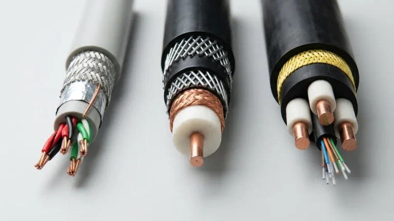
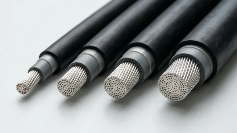
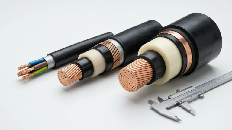
Quick answer: A cable marked 4/0 AWG, 107 mm² or 250 kcmil is not ready for purchase until its connection has been checked. The engineer needs the actual conductor construction and diameter for the lug or terminal, the finished cable diameter for the gland and seal, and the equipment maker’s requirements for temperature, space, support and installation. A matching size label alone does not establish a compatible termination.
This guide is for electrical engineers, switchgear builders and technical buyers who have already chosen a candidate flexible power cable and now need to specify its interfaces. It explains what information to request and how to avoid an RFQ that leaves the connector to guesswork. Final connector selection, installation and approval remain with the responsible equipment designer and the applicable code or authority.
Cable Size and Connection Size Are Different Questions
The conductor size is an electrical design input. It helps the designer check continuous ampacity, voltage drop and short-circuit withstand. The connection adds a different set of constraints: the connector must accept the conductor that will actually be supplied, while the cable entry and support must fit the complete insulated and jacketed cable. Neither decision can be made safely from the other dimension.
For metric cables, IEC 60228:2023 describes nominal cross-sectional areas and requirements that include flexible copper conductors. For some North American extra-flexible constructions, ASTM B172-17(2024) covers rope-lay-stranded copper conductors made from bunch-stranded members. These references help describe the conductor; neither is a substitute for the exact cable drawing and the connector manufacturer’s marked application range.
| Information to confirm | Where to obtain it | Connection decision it supports |
|---|---|---|
| Nominal conductor size and material | Approved cable schedule and product data sheet | Electrical design and initial connector size range |
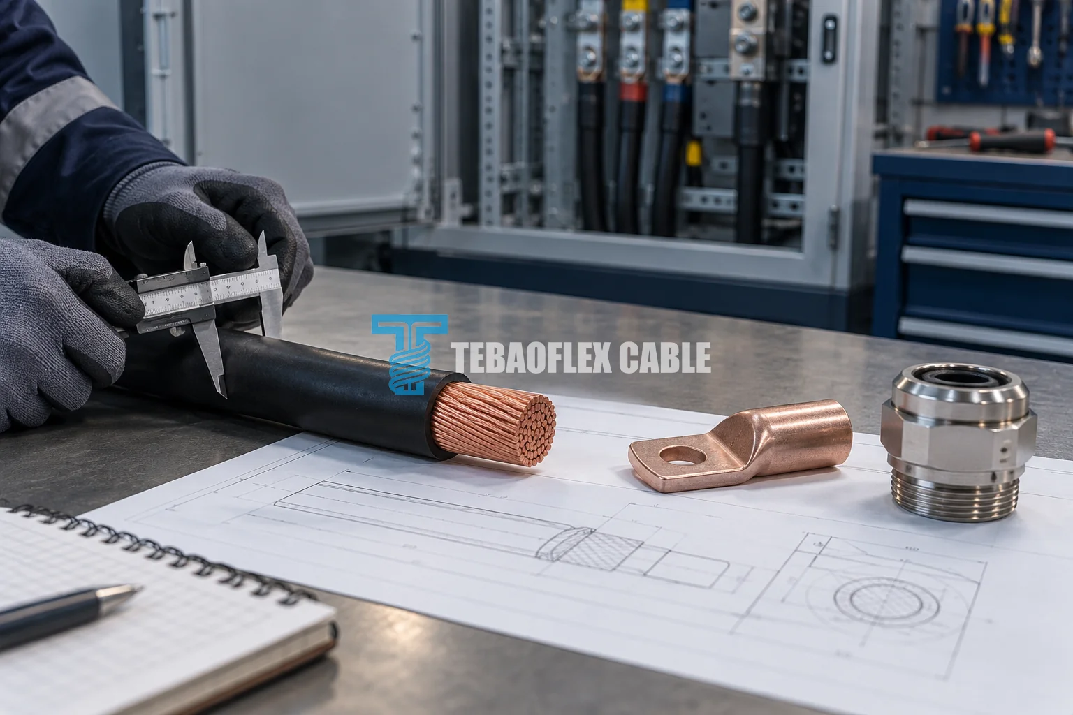
| Stranding designation and actual bare-conductor diameter | Build-specific cable drawing or measured approved sample | Lug or terminal compatibility; conductor preparation |
| Finished cable outside diameter and tolerance | Approved cable drawing | Gland, seal, clamp and enclosure entry fit |
| Connector marking and installation instructions | Selected connector manufacturer | Permitted conductor class, tooling, strip length and tightening method |
| Equipment terminal and thermal limits | Switchgear or machine manufacturer | Connection temperature, stud or pad arrangement, access and spacing |
| Protective-earth or metallic-screen design | System drawing and cable construction drawing | Separate earth and screen termination paths, where applicable |
| Movement and support at cable entry | Equipment layout and route survey | Strain relief, bend path and protection of the connection |
1. Identify the Conductor You Are Actually Terminating
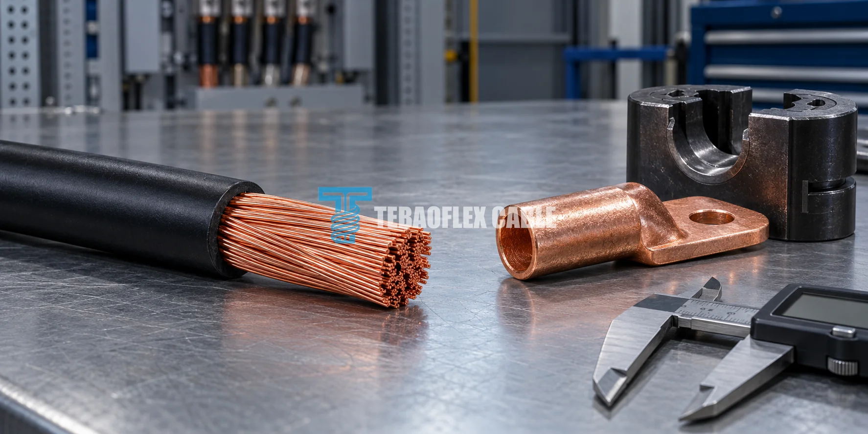
Start with the cable’s model, nominal AWG, kcmil or mm² size, conductor material and stranding designation. The site’s AWG-to-mm² chart and kcmil conversion chart can help interpret the schedule, but a geometric conversion is not a connector approval. Two conductors with similar nominal copper area can have different strand arrangements and bare diameters. Request the diameter and construction of the production cable, not just the size written on a drawing.
Avoid transferring a lug recommendation from one product family to another. A fixed-installation conductor, a flexible IEC Class 5 or Class 6 conductor and a rope-lay DLO construction may be presented under familiar size labels while requiring different connector approvals. If an existing installation is being replaced, photograph the old conductor and its marking, but treat the old lug as a reference to verify rather than proof that a new cable will fit.
2. Check the Connector’s Marking, Not Only Its Size Range
Ask the connector supplier to identify the exact lug, terminal or splice model and the conductor constructions it is evaluated for. The published scope of UL 486A-486B:2025 addresses wire connectors and distinguishes conductor classes, size ranges and additional markings. Its scope does not mean every connector carrying a general AWG range automatically accepts every fine-stranded conductor in that range. The selected connector’s own marking and instructions control the application.
Confirm whether the specified conductor finish and strand construction are permitted, and obtain the required strip length, die or tool identification, crimp sequence and inspection method from that connector’s instructions. If the equipment terminal uses a set screw rather than a separate compression lug, verify that terminal’s accepted conductor class and any manufacturer-approved ferrule or adapter. Do not add a ferrule simply to make an otherwise unsuitable terminal appear to fit.
For a switchgear or generator connection, check the palm, stud pattern, terminal compartment clearance and bend space as part of the same review. A connection can be electrically sized yet impossible to install without forcing the cable into an unacceptable route. The equipment manufacturer and applicable installation rules must resolve the final arrangement.
3. Size the Gland and Strain Relief from the Finished Cable
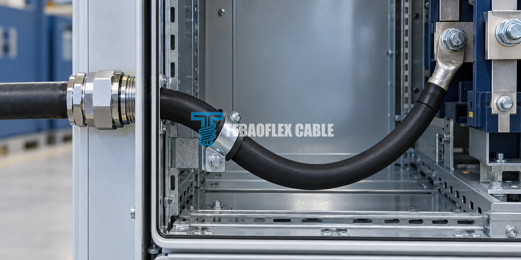
A lug connects to the prepared conductor; a gland or entry seal usually grips or seals the jacketed cable. Use the finished cable outside diameter and its tolerance for the entry review. Also confirm sheath material, sealing requirement, environmental exposure and the type of gland or support specified by the equipment designer. A nominal conductor area is not a gland-size calculation.
Support is especially important where the cable approaches a machine subject to vibration or movement. Determine where the cable is fixed, where it may flex, and whether any load could be transferred to the electrical terminal. A cable described as flexible is not automatically approved for repeated reeling or drag-chain duty; our reeling-cable selection guide covers the separate motion-system review.
4. Keep Thermal, Fault and Earth-Path Checks Separate
A cable’s insulation temperature is not automatically the allowable temperature of the complete connection. Record the limits of the chosen connector, terminal and connected equipment, then apply the installation rules governing the project. The same principle applies to fault duty: cable conductor area alone does not establish the ability of the entire connection to withstand a fault or remain mechanically secure. Use the protection study, device data and approved assembly design rather than a generic current chart.
In a multicore or screened cable, identify the phase conductors, protective-earth conductor, metallic screen and any pilot or ground-check element separately. Their functions and approved termination methods are not interchangeable. A metallic screen should not be silently counted as the protective-earth path, and a small pilot conductor should not be treated as a power or fault-current conductor. The approved electrical design must state how each relevant element is connected.
A Real Product Example: 4/0 AWG DLO Cable
The published TEBAOFLEX 2 kV DLO product data lists its 4/0 AWG construction as 551/24 stranding, with a nominal 14.8 mm bare-conductor diameter and 21.3 mm finished cable diameter. The two measurements serve different interfaces: the connector manufacturer must approve the conductor construction and size, while the gland or clamp must suit the finished cable. These values describe this published DLO construction only; they are not universal dimensions for all 4/0 AWG cables.
Suppose a purchaser sends only “4/0 AWG DLO, 2 kV, 100 m.” The supplier can identify a candidate cable but cannot approve the complete installation. The missing items include the exact terminal or lug, its conductor-class approval and tooling, the cable-entry size, available enclosure space, route support, installation conditions and applicable documentation. The correct response is to close those gaps with the equipment team before committing the connection detail—not to infer that an arbitrary 4/0 lug will fit.
What to Put in a Cable-and-Termination RFQ
A useful RFQ separates confirmed requirements from items still awaiting engineering approval. Send the cable model or an approved equivalent specification, voltage and electrical duty, conductor material and size, required markings, cable length and quantity. Attach the equipment drawing or terminal data, connector or lug model if already selected, gland and entry information, expected movement and environmental conditions, and the required inspection or test documents. If the terminal hardware is not chosen, say so explicitly and request a compatibility review rather than listing an assumed part number.
TEBAOFLEX can supply the build-specific cable information needed for this review and discuss an appropriate flexible power-cable family. The connector and equipment suppliers should confirm their own interface ratings and instructions; the project engineer should approve the complete circuit and installation. For a build-specific quotation, send your cable schedule and termination requirements.
Frequently Asked Questions
Can I choose a lug from AWG or mm² alone?
No. Use the nominal size to narrow the options, then confirm the actual conductor construction and diameter against the selected connector’s marking and instructions. Also check the equipment terminal and installation conditions.
Is the conductor diameter the same as the cable outside diameter?
No. The conductor diameter describes the metal that enters a connector. The finished outside diameter includes the cable’s insulation, jacket and any other layers; it is relevant to a gland, seal, clamp and routing space.
Does a 90°C cable allow every connection to operate at 90°C?
No. The connector, equipment terminal and applicable installation rules may impose different limits. Confirm the rating of the complete connection rather than transferring the cable insulation rating to every component.
Can a metallic screen replace a protective-earth conductor?
Do not assume so. The approved system design must identify each fault-current and bonding path, its capacity and its termination. The screen’s presence by itself is not an equipment-grounding approval.
Source and scope note: IEC 60228:2023 describes insulated-cable conductor requirements; ASTM B172-17(2024) covers specified rope-lay copper conductors; UL 486A-486B:2025 describes the scope and marking framework for wire connectors. Product dimensions in the example come from the linked TEBAOFLEX DLO page. This article is a purchasing and interface-check guide, not a connector listing, electrical design approval or installation instruction. Reviewed 30 October 2026.