Application & Operating Conditions
Type SHD-PCG (Shielded, Permissible, Control, Ground) 2 kV and 5 kV portable mining cables are designed for underground and surface mobile equipment requiring both three-phase shielded trailing power and two dedicated internal control/interlock conductors within a single round jacket. Conforming to ICEA S-75-381 / NEMA WC 58, Type SHD-PCG powers continuous miners, longwall stage loaders, remote-interlocked conveyor drives, roof bolters, and submersible mine pumps without running separate fragile control cords.
Permissible Continuous Miners & Bolters
Provides two insulated pilot/control cores alongside three shielded power phases to carry remote contactor pull-in, emergency stop interlock, and ground-continuity signals.
Interlocked Stage Loaders & Conveyors
Eliminates external control cable snagging by embedding the two control conductors inside two outer interstices of the torsion-filled mold-cured CPE assembly.
Shallow-Water Mine Pump Service
90°C moisture-resistant EPR insulation and vulcanized thermoset CPE outer sheathing withstand standing sump water, coal slurry, hydraulic oil, and rock impact.
SHD-PCG vs. SHD-GC Selection Rule: Specify Type SHD-GC when your load center uses a single Ground-Check wire (2 grounds + 1 GC); specify Type SHD-PCG when your machine control circuit requires two insulated pilot/control wires (2 control cores + grounding).
Cable Construction (ICEA S-75-381 Type SHD-PCG 2kV & 5kV)
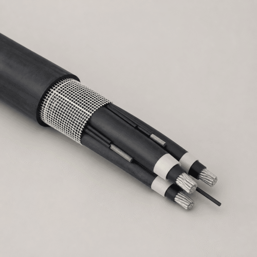
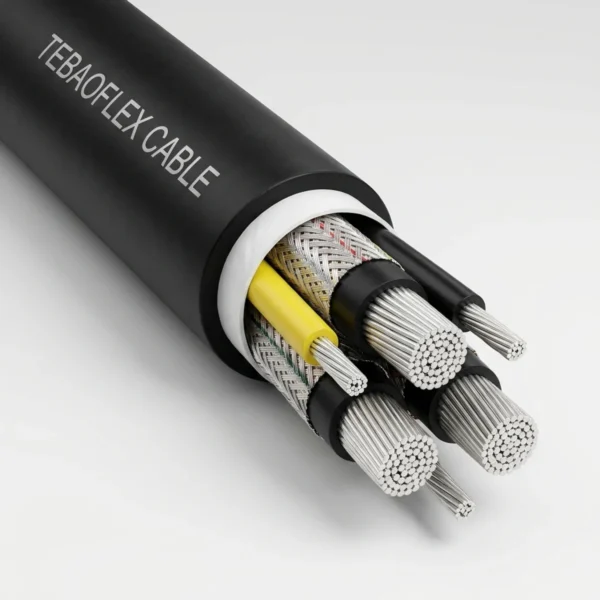
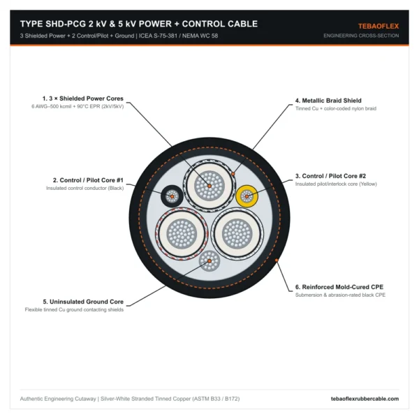
Balanced six-element round core geometry combining three braid-shielded 90°C EPR power phases, two color-coded insulated control/pilot conductors in two outer interstices, and uninsulated tinned copper grounding in the third interstice.
| Layer / Component | Material & ICEA S-75-381 / NEMA WC 58 Engineering Specification |
|---|---|
| 1. Power Conductors (3×) | Flexible rope-lay stranded annealed tinned copper conductors, 6 AWG (133 strands) through 500 kcmil (1,221 strands), per ASTM B172 and ASTM B33. |
| 2. Power Insulation (90°C EPR) | Ethylene Propylene Rubber (EPR) rated +90°C continuous: 70–95 mil wall for 2,000 V service; 110–120 mil wall with extruded semi-conducting stress shields for 5,000 V service. |
| 3. Individual Phase Shielding | Tinned copper and color-coded nylon tracer braid shield (Black, White, Red) applied over each insulated power core. |
| 4. Control / Pilot Conductors (2×) | Two flexible stranded tinned copper control/pilot conductors (10 AWG or 8 AWG by cable size, EPR/PP insulated, color-coded Black and Yellow) positioned in two outer interstices. |
| 5. Grounding System | Uninsulated flexible rope-lay stranded tinned copper grounding conductor laid in the remaining outer interstice in continuous contact with the three phase braid shields. |
| 6. Integral Fill & CPE Jacket | Non-conducting separator tape and torsion-stabilizing elastomeric fill beneath a reinforced mold-cured extra-heavy-duty black CPE jacket suitable for shallow-water submersion. |
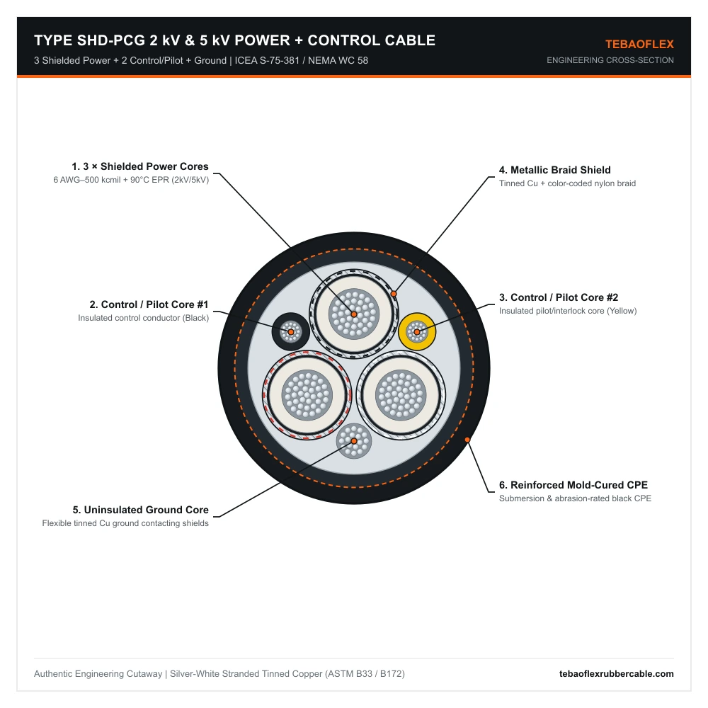
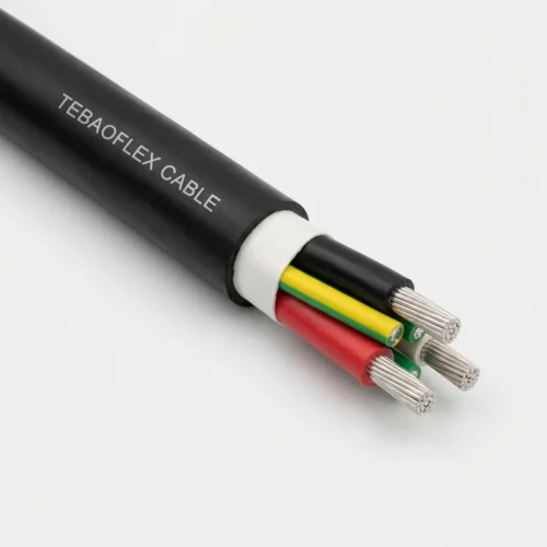
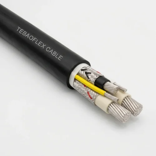
Type SHD-PCG cutaway: 3 braided EPR power phases, 2 insulated control/pilot conductors (Black & Yellow), 1 bare tinned copper ground contacting phase shields, and black CPE jacket.
Technical Characteristics
Electrical, thermal, mechanical, and compliance ratings for 2,000 V and 5,000 V Type SHD-PCG portable cables.
| Parameter | ICEA S-75-381 / NEMA WC 58 Rated Value |
|---|---|
| Rated System Voltages | Up to 2,000 V AC (2 kV Series) | Up to 5,000 V AC (5 kV Medium-Voltage Series) |
| Composite Core Layout | 3 shielded power cores + 2 insulated control/pilot cores (600 V control circuit rating) + grounding |
| Maximum Conductor Temperature | +90°C continuous operation | +250°C short-circuit limit |
| Environmental & Submersion Duty | -40°C cold bend; oil, ozone, abrasion, and shallow mine-water submersion resistant |
| Minimum Bending Radius & Tol. | 6 × overall cable diameter (static); OD tolerance ±5% (2 kV) / +8% -5% (5 kV) |
| Standards & Flame Compliance | ICEA S-75-381 / NEMA WC 58; ASTM B172 & ASTM B33; CSA FT4; MSHA flame-resistant reference |
2000 V & 5000 V Dimensional, Control & Ampacity Data (6 AWG to 500 kcmil)
Complete dual-unit nominal specifications across all 11 standard conductor sizes (6 AWG to 500 kcmil) for both 2,000 V and 5,000 V Type SHD-PCG.
Table 1: Type SHD-PCG 3/C 2000 V (2 kV) — Reinforced Mold-Cured Black CPE (6 AWG to 500 kcmil)
| Power Cores | Area (mm²) | Power Strands | Control Cores (2×) | Ground Core (Strands) | Insul. / Jkt (mil) | Nominal OD (in / mm) | Weight (lb/kft / kg/km) | Ampacity 40°C (A) |
|---|---|---|---|---|---|---|---|---|
| 3 × 6 AWG | 13.30 | 133 | 2 × 10 AWG | 1 × 8 AWG (133) | 70 / 155 | 1.29 / 32.8 | 1,160 / 1,726 | 93 |
| 3 × 4 AWG | 21.15 | 259 | 2 × 10 AWG | 1 × 7 AWG (133) | 70 / 155 | 1.40 / 35.6 | 1,490 / 2,217 | 122 |
| 3 × 2 AWG | 33.62 | 259 | 2 × 10 AWG | 1 × 5 AWG (133) | 70 / 170 | 1.59 / 40.4 | 2,000 / 2,976 | 159 |
| 3 × 1 AWG | 42.41 | 259 | 2 × 8 AWG | 1 × 4 AWG (259) | 80 / 190 | 1.76 / 44.7 | 2,450 / 3,646 | 184 |
| 3 × 1/0 AWG | 53.49 | 266 | 2 × 8 AWG | 1 × 3 AWG (259) | 80 / 190 | 1.86 / 47.2 | 2,840 / 4,226 | 211 |
| 3 × 2/0 AWG | 67.43 | 323 | 2 × 8 AWG | 1 × 2 AWG (259) | 80 / 205 | 2.00 / 50.8 | 3,400 / 5,060 | 243 |
| 3 × 3/0 AWG | 85.01 | 418 | 2 × 8 AWG | 1 × 1 AWG (259) | 80 / 205 | 2.13 / 54.1 | 3,680 / 5,476 | 279 |
| 3 × 4/0 AWG | 107.2 | 532 | 2 × 8 AWG | 1 × 1/0 (266) | 80 / 220 | 2.31 / 58.7 | 4,860 / 7,232 | 321 |
| 3 × 250 kcmil | 126.7 | 627 | 2 × 8 AWG | 1 × 2/0 (323) | 95 / 220 | 2.51 / 63.8 | 5,950 / 8,855 | 355 |
| 3 × 350 kcmil | 177.3 | 888 | 2 × 8 AWG | 1 × 4/0 (532) | 95 / 235 | 2.81 / 71.4 | 7,400 / 11,012 | 435 |
| 3 × 500 kcmil | 253.4 | 1221 | 2 × 8 AWG | 1 × 250 kcmil (627) | 95 / 265 | 3.19 / 81.0 | 10,100 / 15,030 | 536 |
Table 2: Type SHD-PCG 3/C 5000 V (5 kV) — Medium-Voltage Reinforced Black CPE (6 AWG to 500 kcmil)
| Power Cores | Area (mm²) | Power Strands | Control Cores (2×) | Ground Core (Strands) | Insul. / Jkt (mil) | Nominal OD (in / mm) | Weight (lb/kft / kg/km) | Ampacity 40°C (A) |
|---|---|---|---|---|---|---|---|---|
| 3 × 6 AWG | 13.30 | 133 | 2 × 8 AWG | 1 × 8 AWG (133) | 110 / 185 | 1.56 / 39.6 | 1,560 / 2,322 | 93 |
| 3 × 4 AWG | 21.15 | 259 | 2 × 8 AWG | 1 × 7 AWG (133) | 110 / 185 | 1.68 / 42.7 | 1,920 / 2,857 | 122 |
| 3 × 2 AWG | 33.62 | 259 | 2 × 8 AWG | 1 × 5 AWG (133) | 110 / 205 | 1.87 / 47.5 | 2,500 / 3,720 | 159 |
| 3 × 1 AWG | 42.41 | 259 | 2 × 8 AWG | 1 × 4 AWG (259) | 110 / 205 | 1.95 / 49.5 | 2,860 / 4,256 | 184 |
| 3 × 1/0 AWG | 53.49 | 266 | 2 × 8 AWG | 1 × 3 AWG (259) | 110 / 220 | 2.08 / 52.8 | 3,390 / 5,045 | 211 |
| 3 × 2/0 AWG | 67.43 | 323 | 2 × 8 AWG | 1 × 2 AWG (259) | 110 / 220 | 2.20 / 55.9 | 3,830 / 5,700 | 243 |
| 3 × 3/0 AWG | 85.01 | 418 | 2 × 8 AWG | 1 × 1 AWG (259) | 110 / 235 | 2.36 / 59.9 | 4,418 / 6,575 | 279 |
| 3 × 4/0 AWG | 107.2 | 532 | 2 × 8 AWG | 1 × 1/0 (266) | 110 / 235 | 2.50 / 63.5 | 5,300 / 7,887 | 321 |
| 3 × 250 kcmil | 126.7 | 627 | 2 × 8 AWG | 1 × 2/0 (323) | 120 / 250 | 2.69 / 68.3 | 6,450 / 9,599 | 355 |
| 3 × 350 kcmil | 177.3 | 888 | 2 × 8 AWG | 1 × 4/0 (532) | 120 / 265 | 2.95 / 74.9 | 7,880 / 11,727 | 435 |
| 3 × 500 kcmil | 253.4 | 1221 | 2 × 8 AWG | 1 × 250 kcmil (627) | 120 / 280 | 3.31 / 84.1 | 10,440 / 15,536 | 536 |
Type SHD-PCG vs. Related ICEA S-75-381 Mining Cables
Compare power-plus-control Type SHD-PCG against standard SHD-GC, center-pilot SHD-CGC, and flat Type SHD.
| Mining Cable Model | Voltage Class, Ground / Shield Architecture & Primary Mining Duty |
|---|---|
| Type SHD-GC (2kV / 5kV / 8kV) | Round 3 shielded power cores + 2 interstitial bare tinned grounds + 1 interstitial yellow PP ground-check core for general trailing miners, drills, and pit shovels. |
| Type SHD-GC (15kV & 25kV) | High-voltage 210 mil (15kV) and 260 mil (25kV) EPR shielded trailing cable for ultra-class walking draglines, electric rope shovels, and mobile pit substations. |
| Type SHD Flat (2kV) | Flat parallel 3 shielded power cores + 1 grounding core (no GC monitor core) engineered for high-layer-count level-wind shuttle-car and continuous-miner reels. |
| Type SHD-CGC (2kV & 5kV) | Round longwall shearer cable with 16 AWG yellow Ground-Check positioned along the neutral geometric center axis + 3 symmetrical grounds to prevent dynamic S-bend pilot breakage. |
| Type SHD-PCG (2kV & 5kV) | Composite round cable integrating 3 shielded power cores + 2 insulated control/pilot cores + grounding for permissible remote-interlock underground mining equipment. |
Frequently Asked Questions (FAQ)
Engineering FAQs on Type SHD-PCG control conductors, grounding equivalence, and coupler pinouts.
What does “PCG” stand for in Type SHD-PCG mining cable?
In North American mining nomenclature (ICEA S-75-381 / MSHA), PCG stands for Permissible, Control, and Ground—indicating a cable incorporating two insulated control/pilot conductors and a full-capacity equipment grounding conductor alongside the shielded power phases.
Does a single ground wire in Type SHD-PCG provide the same fault capacity as the two ground wires in Type SHD-GC?
Yes. The single bare tinned copper ground conductor in Type SHD-PCG is upsized by 3 AWG steps (doubling circular mil area—for example, 1 × 2 AWG in a 2/0 cable versus 2 × 5 AWG) so total ground conductance ≥ 50% of one power phase per ICEA S-75-381 and MSHA 30 CFR Part 75.
Can the two control conductors in Type SHD-PCG also be shielded on request?
Yes. Standard builds supply high-dielectric EPR/PP insulated #10 or #8 AWG control conductors, and custom builds can add individual metallic braid shields over the control cores to suppress VFD or high-current switching noise.
Request a Type SHD-PCG 2kV or 5kV Mining Cable Quote
Share your voltage rating (2 kV or 5 kV), power gauge (6 AWG to 500 kcmil), control core shield requirement, and drum length for fast factory quotation.
Explore All Mining & Tunneling Cables