Application & Operating Conditions
AS/NZS 2802 Type 451 is a Class 1 composite screened reeling and trailing cable (3.3 kV to 22 kV, 33 kV on request; 25–150 mm²) featuring a reduced-size interstitial pilot (9 mm² or 13.2 mm²) thickened with insulating elastomer to match the outer diameter of the two interstitial earth cores for streamlined HV coupler termination.
Direct HV Coupler Pilot Fitment
Standardizes pilot conductor cross-section at 9 mm² (3.3/6.6 kV up to 95 mm²) or 13.2 mm² (120–150 mm² & all 11/22 kV sizes), fitting standard HV mining plugs and slip-ring brush gear without strand trimming.
Preserved Interstitial Lay Symmetry
Extra radial insulating elastomer over the reduced pilot keeps its finished core diameter identical to the two 8–39.5 mm² interstitial earths, preventing core migration during drum reeling.
Open-Cut & Port Reeling Duty
Polyaramid-reinforced XHD-85-PCP sheath and Class 1 XR-EP-90 EPR insulation serve stacker-reclaimers, ship loaders, wharf cranes, shovels, and mobile crushers.
Need 185–300 mm² Cross-Sections or an Equal-Size Pilot? For larger phase conductors up to 300 mm² or full-size 18–80 mm² pilots on multi-kilometer runs, view AS/NZS 2802 Type 450.
Cable Construction (AS/NZS 2802 Type 451)
Type 451 shares the exact overall diameter, sheath wall, and phase-screen architecture of Type 450 across 25–150 mm², substituting a heavy-wall elastomer-insulated reduced pilot in one of the three outer interstices.
| Layer / Component | Material & AS/NZS 2802 Specification |
|---|---|
| 1. Phase Conductors | Flexible stranded tinned annealed copper, three power cores (25 mm² to 150 mm²) |
| 2. Conductor Screen | Semiconductive barrier tape and extruded semiconductive elastomeric conductor screen |
| 3. Class 1 EPR Insulation | Cross-linked XR-EP-90 EPR Class 1 compound (2.2–2.4 mm @ 3.3 kV; 3.0 mm @ 6.6 kV; 5.0 mm @ 11 kV; 7.6 mm @ 22 kV) |
| 4. Composite Insulation Screen | Composite screen of tinned annealed copper wire and polyester yarn with Red, White, and Blue braid tracers (7.9–31 mm²/phase) |
| 5. Two Earths + Reduced Pilot | Two elastomer-covered interstitial earths (8–39.5 mm²) + one reduced-size elastomer-covered interstitial pilot (9 mm² or 13.2 mm²) |
| 6. Polyaramid-Reinforced Sheath | Extra heavy-duty black XHD-85-PCP sheath (4.8–7.4 mm) incorporating polyaramid braid reinforcement |
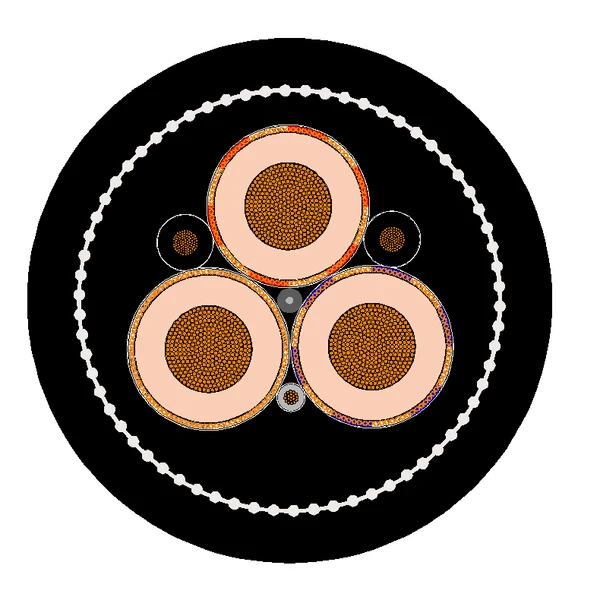
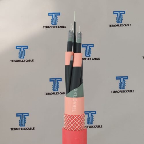
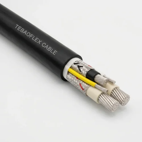
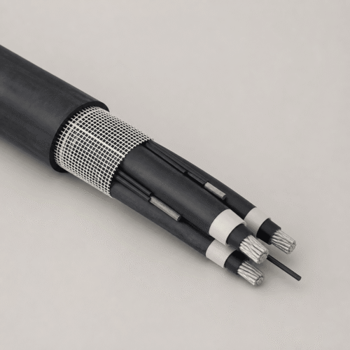
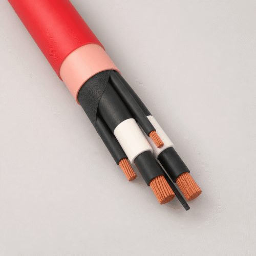
Type 451 Cross-Section Geometry: Three composite-screened Class 1 XR-EP-90 phase cores, two full-sized interstitial earth cores, and one reduced-copper interstitial pilot built out to matching outer diameter.
Technical Characteristics
Manufactured to AS/NZS 2802 Class 1, Type 451 combines full fault-current composite + interstitial earth return capacity with standardized 9 mm² and 13.2 mm² pilot terminations.
| Parameter | AS/NZS 2802 Rated Value |
|---|---|
| Manufacturing Standard | AS/NZS 2802 Class 1 (Reeling and trailing cables for mining and general use) |
| Rated Voltages & Sub-Types | 451.3 (3.3 kV) | 451.6 (6.6 kV) | 451.11 (11 kV) | 451.22 (22 kV) | 451.33 (33 kV on request) |
| Standardized Pilot Sizes | 9 mm² (451.3 & 451.6, 25–95 mm²) | 13.2 mm² (451.3/451.6 120–150 mm² & all 451.11 / 451.22 sizes) |
| Earth Conductors & Screens | 2 × 8–39.5 mm² interstitial earths + 3 × 7.9–31 mm²/phase composite copper/polyester screens |
| Operating Temperature Range | −25 °C min. installation to +90 °C max. continuous conductor (250 °C short-circuit) |
| Mechanical & Flame Rating | Polyaramid anti-torsion braid in XHD-85-PCP sheath | C1 flame retardant | Oil & water resistant |
Specification, Screen, Earth & Reduced-Pilot Data (27 Standard Sizes, 3.3 kV – 22 kV)
Complete AS/NZS 2802 Type 451 electrical and dimensional tables detailing separate Earth Conductor Area and Reduced Pilot Area columns alongside overall cable diameter and mass.
Type 451.3 — Rated Voltage: 3.3/3.3 kV (25 mm² to 150 mm² | 7 Sizes)
| Area (mm²) | Cond. Dia. (mm) | Insul. (mm) | AC Res. (Ω/km) | React. (Ω/km) | Volt Drop (mV/A·m) | Cap. (μF/km) | Screen (mm²/ph) | Earth Each (mm²) | Pilot (mm²) | Sheath (mm) | Cable Dia. (mm) | Mass (kg/100m) |
|---|---|---|---|---|---|---|---|---|---|---|---|---|
| 3 × 25 | 7.2 | 2.2 | 0.951 | 0.118 | 1.66 | 0.395 | 7.9 | 8 | 9 | 4.8 | 46.7 | 360 |
| 3 × 35 | 8.4 | 2.2 | 0.698 | 0.113 | 1.22 | 0.437 | 8.5 | 8 | 9 | 5.1 | 49.7 | 415 |
| 3 × 50 | 9.7 | 2.4 | 0.523 | 0.109 | 0.925 | 0.450 | 9.3 | 12 | 9 | 5.6 | 54.5 | 510 |
| 3 × 70 | 12.0 | 2.4 | 0.346 | 0.103 | 0.625 | 0.525 | 14 | 18 | 9 | 6.0 | 60.5 | 655 |
| 3 × 95 | 13.3 | 2.4 | 0.271 | 0.0986 | 0.500 | 0.563 | 15 | 25 | 9 | 6.3 | 63.9 | 755 |
| 3 × 120 | 15.3 | 2.4 | 0.210 | 0.0947 | 0.399 | 0.628 | 16 | 31 | 13.2 | 6.4 | 68.4 | 890 |
| 3 × 150 | 17.2 | 2.4 | 0.166 | 0.0918 | 0.329 | 0.687 | 17 | 39.5 | 13.2 | 6.6 | 72.8 | 1050 |
Type 451.6 — Rated Voltage: 6.6/6.6 kV (25 mm² to 150 mm² | 7 Sizes)
| Area (mm²) | Cond. Dia. (mm) | Insul. (mm) | AC Res. (Ω/km) | React. (Ω/km) | Volt Drop (mV/A·m) | Cap. (μF/km) | Screen (mm²/ph) | Earth Each (mm²) | Pilot (mm²) | Sheath (mm) | Cable Dia. (mm) | Mass (kg/100m) |
|---|---|---|---|---|---|---|---|---|---|---|---|---|
| 3 × 25 | 7.2 | 3.0 | 0.951 | 0.124 | 1.66 | 0.309 | 8.8 | 8 | 9 | 5.2 | 51.1 | 415 |
| 3 × 35 | 8.4 | 3.0 | 0.698 | 0.118 | 1.23 | 0.340 | 9.3 | 8 | 9 | 5.5 | 54.2 | 470 |
| 3 × 50 | 9.7 | 3.0 | 0.523 | 0.113 | 0.927 | 0.375 | 10 | 12 | 9 | 5.9 | 57.8 | 555 |
| 3 × 70 | 12.0 | 3.0 | 0.346 | 0.106 | 0.627 | 0.435 | 15 | 18 | 9 | 6.3 | 63.9 | 705 |
| 3 × 95 | 13.3 | 3.0 | 0.271 | 0.102 | 0.502 | 0.465 | 16 | 25 | 9 | 6.4 | 66.8 | 800 |
| 3 × 120 | 15.3 | 3.0 | 0.210 | 0.0979 | 0.401 | 0.518 | 17 | 31 | 13.2 | 6.5 | 71.4 | 940 |
| 3 × 150 | 17.2 | 3.0 | 0.166 | 0.0948 | 0.331 | 0.566 | 18 | 39.5 | 13.2 | 6.6 | 75.5 | 1100 |
Type 451.11 — Rated Voltage: 11/11 kV (25 mm² to 150 mm² | 7 Sizes)
| Area (mm²) | Cond. Dia. (mm) | Insul. (mm) | AC Res. (Ω/km) | React. (Ω/km) | Volt Drop (mV/A·m) | Cap. (μF/km) | Screen (mm²/ph) | Earth Each (mm²) | Pilot (mm²) | Sheath (mm) | Cable Dia. (mm) | Mass (kg/100m) |
|---|---|---|---|---|---|---|---|---|---|---|---|---|
| 3 × 25 | 7.2 | 5.0 | 0.951 | 0.136 | 1.66 | 0.217 | 14 | 8 | 13.2 | 6.3 | 62.3 | 570 |
| 3 × 35 | 8.4 | 5.0 | 0.698 | 0.129 | 1.23 | 0.236 | 15 | 8 | 13.2 | 6.4 | 65.0 | 630 |
| 3 × 50 | 9.7 | 5.0 | 0.523 | 0.123 | 0.931 | 0.258 | 16 | 12 | 13.2 | 6.5 | 68.1 | 715 |
| 3 × 70 | 12.0 | 5.0 | 0.346 | 0.115 | 0.632 | 0.296 | 17 | 18 | 13.2 | 6.6 | 73.1 | 850 |
| 3 × 95 | 13.3 | 5.0 | 0.271 | 0.111 | 0.507 | 0.317 | 18 | 25 | 13.2 | 6.7 | 76.1 | 955 |
| 3 × 120 | 15.3 | 5.0 | 0.210 | 0.107 | 0.408 | 0.350 | 20 | 31 | 13.2 | 6.9 | 80.7 | 1105 |
| 3 × 150 | 17.2 | 5.0 | 0.166 | 0.103 | 0.338 | 0.381 | 26 | 39.5 | 13.2 | 7.0 | 85.2 | 1295 |
Type 451.22 — Rated Voltage: 22/22 kV (35 mm² to 150 mm² | 6 Sizes)
| Area (mm²) | Cond. Dia. (mm) | Insul. (mm) | AC Res. (Ω/km) | React. (Ω/km) | Volt Drop (mV/A·m) | Cap. (μF/km) | Screen (mm²/ph) | Earth Each (mm²) | Pilot (mm²) | Sheath (mm) | Cable Dia. (mm) | Mass (kg/100m) |
|---|---|---|---|---|---|---|---|---|---|---|---|---|
| 3 × 35 | 8.4 | 7.6 | 0.698 | 0.142 | 1.23 | 0.178 | 19 | 8 | 13.2 | 6.8 | 77.2 | 840 |
| 3 × 50 | 9.7 | 7.6 | 0.523 | 0.135 | 0.936 | 0.194 | 20 | 12 | 13.2 | 6.9 | 80.2 | 930 |
| 3 × 70 | 12.0 | 7.6 | 0.346 | 0.127 | 0.638 | 0.219 | 27 | 18 | 13.2 | 7.0 | 85.6 | 1100 |
| 3 × 95 | 13.3 | 7.6 | 0.271 | 0.122 | 0.515 | 0.234 | 27 | 25 | 13.2 | 7.2 | 88.9 | 1220 |
| 3 × 120 | 15.3 | 7.6 | 0.210 | 0.117 | 0.416 | 0.256 | 29 | 31 | 13.2 | 7.3 | 93.4 | 1380 |
| 3 × 150 | 17.2 | 7.6 | 0.165 | 0.113 | 0.346 | 0.276 | 31 | 39.5 | 13.2 | 7.4 | 97.5 | 1560 |
Selection: Type 451 vs. Type 450 vs. Type 455
Within the AS/NZS 2802 Class 1 reeling family, Type 451, Type 450, and Type 455 differ in pilot conductor cross-section and phase-screen construction.
| Cable Model | Screen Type, Pilot Sizing & Termination Advantage |
|---|---|
| Type 451 (This Product) | Composite metallic screen + 2 earths + 1 reduced pilot (9 or 13.2 mm²) across 25–150 mm² (3.3–22 kV). Eliminates oversized pilot crimps inside HV couplers and crane collector slip-ring boxes. |
| Type 450 (Equal Pilot) | Type 450 scales the interstitial pilot equally with the earth cores (up to 80 mm² on 300 mm²) for ultra-long trailing runs or phase sizes above 150 mm². |
| Type 455 (Semiconductive) | Type 455 replaces the copper/polyester braid with an extruded semiconductive elastomer screen (3.3–11 kV) to eliminate metallic braid strand fatigue on tight reeling drums. |
Frequently Asked Questions (FAQ)
Technical answers explaining why engineers specify Type 451 over Type 450 for HV plug-and-receptacle systems.
Why choose Type 451 instead of Type 450 on 70 mm² to 150 mm² reeling cables?
On a 150 mm² cable, Type 450 supplies a 39.5 mm² pilot conductor that is too large to enter standard HV coupler pilot pins without step-down splices. Type 451 caps the pilot at 9 mm² or 13.2 mm² while maintaining the exact same overall cable diameter (e.g., 85.2 mm at 11 kV 150 mm²) for identical cable gland clamping.
Does the smaller 9 mm² or 13.2 mm² pilot make Type 451 asymmetric under drum tension?
No. The reduced copper pilot is extruded with a thicker radial wall of insulating elastomer so its finished outer diameter equals the two interstitial earth cores, preserving circular 3+3 lay geometry inside the polyaramid-reinforced XHD-85-PCP sheath.
Are Type 451 cables available with coloured outer sheaths for open-cut visibility?
Standard production uses UV-stabilized carbon-black XHD-85-PCP, with high-visibility yellow, orange, or red outer elastomer sheaths and custom CSP/TPU jacket compounds available to mine or port site specifications.
Request a Quote for AS/NZS 2802 Type 451 Reduced-Pilot Reeling Cables
Send us your voltage grade (3.3 kV to 33 kV), phase cross-section (25–150 mm²), HV coupler model, and drum length for fast factory quotation.
Explore All Mining & Tunneling Cables