Application & Operating Conditions
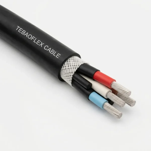
AS/NZS 1802 Type 241 is the industry-standard semiconductive elastomer screened flexible mining cable (1.1/1.1 kV to 11/11 kV) for underground coal and hard-rock mines. Replacing metallic wire braids with semiconductive elastomer screens and three interstitial earth cores makes Type 241 markedly lighter, smaller in diameter, and more resistant to cyclic flex fatigue on mobile face equipment.
Continuous Miners & Bolter-Miners
Eliminates broken metallic braid wires that can pierce core insulation during relentless dragging, coiling, and floor-turnaround flexing behind underground continuous miners and roadheaders.
Longwall Monorails & DCB Feeders
Widely installed on overhead monorail loops supplying distribution control boxes (DCBs), shearer loaders, armored face conveyors, and high-capacity underground dewatering pumps.
Reinforced HD-85-PCP Protection
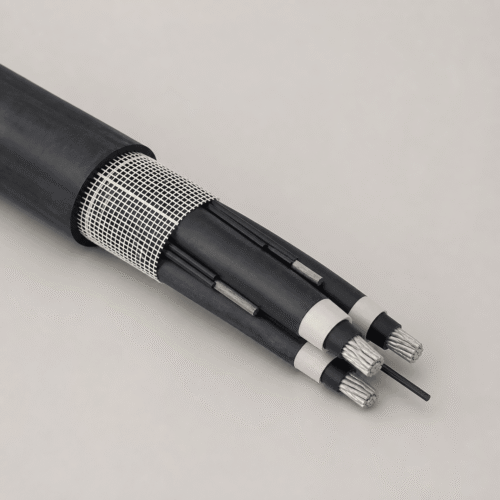
An integral open-weave anti-tear reinforcement braid beneath the heavy-duty HD-85-PCP outer sheath resists rib abrasion, rockfall impact, oil immersion, and C1 vertical flame spread.
Tighter Monorail Loop Requirement? Where congested underground roadways demand even narrower monorail suspension loops in 70–300 mm² cross-sections, specify our extra-flexible AS/NZS 1802 Type 241SF (Superflex) variant.
Cable Construction (AS/NZS 1802 Type 241)
Type 241 achieves continuous earth-fault contact without metallic core braids by pairing semiconductive-elastomer-screened R-EP-90 phase cores in intimate contact with three semiconductive-covered interstitial earth conductors around a central extensible pilot.
| Layer / Component | Material & AS/NZS 1802 Specification |
|---|---|
| 1. Phase Conductors | Flexible stranded tinned annealed copper, three phase cores (6–300 mm²) |
| 2. Conductor Separator / Screen | Polyester separator where necessary for 1.1/1.1 kV; extruded semi-conductive screen for 3.3 kV and above |
| 3. Insulation & Core ID | Ethylene-propylene rubber (R-EP-90 EPR) with durably printed core numbers / phase colours for unambiguous termination |
| 4. Phase Insulation Screen | Extruded semi-conductive elastomer screen over each phase core (non-metallic flex-resistant earth-fault barrier) |
| 5. Interstitial Earth Cores | Three semi-conductive elastomer covered flexible tinned copper earth cores (1–50 mm² each) laid in direct conductive contact in the outer interstices |
| 6. Central Pilot Core | Single extensible central pilot core located at the geometric center of the three phase cores |
| 7. Reinforcement & Sheath | Open-weave textile reinforcement braid embedded under a heavy-duty HD-85-PCP polychloroprene outer sheath (3.8–11.0 mm wall) |
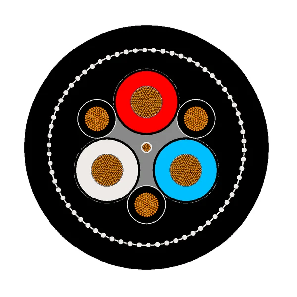
Type 241 Cross-Section Geometry: Open-weave reinforcement ring under HD-85-PCP sheath, three semiconductive-screened EPR phase cores, three semiconductive-covered interstitial earths, and one central pilot.
Technical Characteristics
Compliant with AS/NZS 1802 across 1.1/1.1 kV to 11/11 kV, Type 241 general-purpose trailing and feeder cables combine +90 °C continuous operating capacity, reduced outer diameters versus metallic-screened cables, and C1 flame retardancy.
| Parameter | AS/NZS 1802 Rated Value |
|---|---|
| Manufacturing Standard | AS/NZS 1802 (Electric cables — Reeling and trailing — For underground coal mining applications) |
| Voltage Grades & Sub-Types | Type 241.1 (1.1/1.1 kV) | Type 241.3 (3.3/3.3 kV) | Type 241.6 (6.6/6.6 kV) | Type 241.11 (11/11 kV) |
| Phase Cross-Section Range | 6–300 mm² (1.1 kV) | 16–300 mm² (3.3 kV & 6.6 kV) | 25–240 mm² (11 kV) |
| Earth Conductor Sizing (Each of 3) | 1–35.2 mm² (1.1 kV) | 3–50 mm² (3.3 & 6.6 kV) | 4.5–39.5 mm² (11 kV) |
| Max. Continuous Conductor Temp. | +90 °C |
| Minimum Installation Temperature | −25 °C |
| Installation Conditions | In free air, in underground ducts, on monorails, and for mobile mining machines |
| Oil, Water & Flame Performance | Excellent immersion performance, superior dynamic flexibility, and C1 flame retardancy |
Specification & Dimensional Data (44 Standard Sizes)
Overview of all four AS/NZS 1802 Type 241 voltage classes is shown in the quick-reference matrix below, followed by full dimensional, impedance, interstitial earth, and mass tables.
| Sub-Type | Voltage | Area Range | EPR Insul. | Earth Core (mm²) | Sheath Wall | OD Range | Mass (kg/100m) |
|---|---|---|---|---|---|---|---|
| Type 241.1 | 1.1/1.1 kV | 6–300 mm² (13) | 1.5–3.0 mm | 1–35.2 | 3.8–8.7 mm | 29.9–90.8 mm | 130–1670 |
| Type 241.3 | 3.3/3.3 kV | 16–300 mm² (11) | 3.0 mm | 3–50 | 5.0–9.1 mm | 45.0–92.3 mm | 285–1735 |
| Type 241.6 | 6.6/6.6 kV | 16–300 mm² (11) | 5.0 mm | 3–50 | 6.1–10.2 mm | 55.9–104 mm | 410–1995 |
| Type 241.11 | 11/11 kV | 25–240 mm² (9) | 7.6 mm | 4.5–39.5 | 7.8–11.0 mm | 73.8–111 mm | 720–2035 |
Type 241.1 — Rated Voltage: 1.1/1.1 kV (6 mm² to 300 mm² | 13 Sizes)
Type 241.1 (1.1/1.1 kV): 1.5–3.0 mm R-EP-90 EPR insulation, semiconductive elastomer screen, three interstitial earth cores (1–35.2 mm² each), central pilot, and open-weave reinforced HD-85-PCP sheath.
| Area (mm²) | Cond. Dia. (mm) | Insul. (mm) | AC Res. (Ω/km) | React. (Ω/km) | Volt Drop (mV/A·m) | Cap. (µF/km) | Earth (mm²) | Sheath (mm) | Cable Dia. (mm) | Mass (kg/100m) |
|---|---|---|---|---|---|---|---|---|---|---|
| 6 | 3.5 | 1.5 | 4.32 | 0.139 | 7.49 | 0.259 | 1 | 3.8 | 29.9 | 130 |
| 10 | 4.6 | 1.5 | 2.58 | 0.127 | 4.47 | 0.314 | 1.5 | 3.8 | 32.0 | 155 |
| 16 | 6.2 | 1.6 | 1.58 | 0.116 | 2.74 | 0.379 | 3 | 3.9 | 35.9 | 200 |
| 25 | 7.2 | 1.6 | 0.951 | 0.110 | 1.66 | 0.432 | 4.5 | 4.2 | 38.9 | 255 |
| 35 | 8.4 | 1.6 | 0.698 | 0.106 | 1.22 | 0.493 | 6 | 4.4 | 42.0 | 310 |
| 50 | 9.7 | 1.7 | 0.523 | 0.102 | 0.923 | 0.526 | 8 | 4.9 | 46.3 | 380 |
| 70 | 12.0 | 1.8 | 0.346 | 0.0965 | 0.622 | 0.599 | 12.5 | 5.3 | 52.4 | 510 |
| 95 | 13.3 | 2.0 | 0.271 | 0.0942 | 0.497 | 0.591 | 12.5 | 5.8 | 57.1 | 605 |
| 120 | 15.3 | 2.1 | 0.210 | 0.0912 | 0.397 | 0.640 | 13.75 | 6.3 | 62.9 | 745 |
| 150 | 17.2 | 2.3 | 0.166 | 0.0896 | 0.327 | 0.652 | 17 | 6.7 | 68.6 | 910 |
| 185 | 18.8 | 2.5 | 0.137 | 0.0885 | 0.283 | 0.657 | 22 | 7.3 | 74.4 | 1085 |
| 240 | 21.7 | 2.8 | 0.107 | 0.0868 | 0.239 | 0.672 | 27 | 8.0 | 83.2 | 1370 |
| 300 | 24.3 | 3.0 | 0.0851 | 0.0848 | 0.208 | 0.719 | 35.2 | 8.7 | 90.8 | 1670 |
Type 241.3 — Rated Voltage: 3.3/3.3 kV (16 mm² to 300 mm² | 11 Sizes)
Type 241.3 (3.3/3.3 kV): Semi-conductive conductor & insulation screens, 3.0 mm R-EP-90 EPR insulation, three interstitial earth cores (3–50 mm² each), central pilot, and reinforced HD-85-PCP sheath.
| Area (mm²) | Cond. Dia. (mm) | Insul. (mm) | AC Res. (Ω/km) | React. (Ω/km) | Volt Drop (mV/A·m) | Cap. (µF/km) | Earth (mm²) | Sheath (mm) | Cable Dia. (mm) | Mass (kg/100m) |
|---|---|---|---|---|---|---|---|---|---|---|
| 16 | 6.2 | 3.0 | 1.58 | 0.129 | 2.75 | 0.255 | 3 | 5.0 | 45.0 | 285 |
| 25 | 7.2 | 3.0 | 0.951 | 0.123 | 1.66 | 0.280 | 4.5 | 5.3 | 48.2 | 350 |
| 35 | 8.4 | 3.0 | 0.698 | 0.117 | 1.23 | 0.311 | 6 | 5.6 | 51.2 | 410 |
| 50 | 9.7 | 3.0 | 0.523 | 0.112 | 0.926 | 0.347 | 8 | 6.0 | 55.0 | 485 |
| 70 | 12.0 | 3.0 | 0.346 | 0.105 | 0.626 | 0.408 | 12.5 | 6.4 | 60.6 | 620 |
| 95 | 13.3 | 3.0 | 0.271 | 0.101 | 0.501 | 0.439 | 16 | 6.8 | 64.2 | 715 |
| 120 | 15.3 | 3.0 | 0.210 | 0.0965 | 0.400 | 0.492 | 20 | 7.2 | 69.3 | 855 |
| 150 | 17.2 | 3.0 | 0.166 | 0.0934 | 0.330 | 0.541 | 27 | 7.6 | 74.2 | 1030 |
| 185 | 18.8 | 3.0 | 0.137 | 0.0911 | 0.285 | 0.584 | 35.2 | 8.0 | 78.5 | 1190 |
| 240 | 21.7 | 3.0 | 0.107 | 0.0878 | 0.240 | 0.659 | 39.5 | 8.6 | 85.8 | 1450 |
| 300 | 24.3 | 3.0 | 0.0851 | 0.0854 | 0.209 | 0.727 | 50 | 9.1 | 92.3 | 1735 |
Type 241.6 — Rated Voltage: 6.6/6.6 kV (16 mm² to 300 mm² | 11 Sizes) — Click to Expand
Type 241.6 (6.6/6.6 kV): Semi-conductive conductor & insulation screens, 5.0 mm R-EP-90 EPR insulation, three interstitial earth cores (3–50 mm² each), central pilot, and reinforced HD-85-PCP sheath.
| Area (mm²) | Cond. Dia. (mm) | Insul. (mm) | AC Res. (Ω/km) | React. (Ω/km) | Volt Drop (mV/A·m) | Cap. (µF/km) | Earth (mm²) | Sheath (mm) | Cable Dia. (mm) | Mass (kg/100m) |
|---|---|---|---|---|---|---|---|---|---|---|
| 16 | 6.2 | 5.0 | 1.58 | 0.141 | 2.75 | 0.181 | 3 | 6.1 | 55.9 | 410 |
| 25 | 7.2 | 5.0 | 0.951 | 0.135 | 1.66 | 0.193 | 4.5 | 6.4 | 59.4 | 495 |
| 35 | 8.4 | 5.0 | 0.698 | 0.129 | 1.23 | 0.212 | 6 | 6.7 | 62.5 | 560 |
| 50 | 9.7 | 5.0 | 0.523 | 0.123 | 0.931 | 0.234 | 8 | 7.1 | 66.2 | 645 |
| 70 | 12.0 | 5.0 | 0.346 | 0.115 | 0.632 | 0.271 | 12.5 | 7.4 | 71.7 | 790 |
| 95 | 13.3 | 5.0 | 0.271 | 0.111 | 0.507 | 0.292 | 16 | 7.9 | 75.5 | 905 |
| 120 | 15.3 | 5.0 | 0.210 | 0.106 | 0.407 | 0.325 | 20 | 8.3 | 80.6 | 1065 |
| 150 | 17.2 | 5.0 | 0.166 | 0.102 | 0.337 | 0.354 | 27 | 8.6 | 85.1 | 1235 |
| 185 | 18.8 | 5.0 | 0.137 | 0.0997 | 0.293 | 0.381 | 35.2 | 9.0 | 89.5 | 1410 |
| 240 | 21.7 | 5.0 | 0.106 | 0.0957 | 0.247 | 0.426 | 39.5 | 9.6 | 96.8 | 1685 |
| 300 | 24.3 | 5.0 | 0.0847 | 0.0927 | 0.217 | 0.467 | 50 | 10.2 | 104 | 1995 |
Type 241.11 — Rated Voltage: 11/11 kV (25 mm² to 240 mm² | 9 Sizes) — Click to Expand
Type 241.11 (11/11 kV): Semi-conductive conductor & insulation screens, 7.6 mm R-EP-90 EPR insulation, three interstitial earth cores (4.5–39.5 mm² each), central pilot, and reinforced HD-85-PCP sheath.
| Area (mm²) | Cond. Dia. (mm) | Insul. (mm) | AC Res. (Ω/km) | React. (Ω/km) | Volt Drop (mV/A·m) | Cap. (µF/km) | Earth (mm²) | Sheath (mm) | Cable Dia. (mm) | Mass (kg/100m) |
|---|---|---|---|---|---|---|---|---|---|---|
| 25 | 7.2 | 7.6 | 0.951 | 0.148 | 1.67 | 0.150 | 4.5 | 7.8 | 73.8 | 720 |
| 35 | 8.4 | 7.6 | 0.698 | 0.141 | 1.23 | 0.163 | 6 | 8.1 | 76.8 | 800 |
| 50 | 9.7 | 7.6 | 0.523 | 0.135 | 0.936 | 0.178 | 8 | 8.5 | 80.5 | 895 |
| 70 | 12.0 | 7.6 | 0.346 | 0.126 | 0.638 | 0.204 | 12.5 | 8.9 | 86.1 | 1060 |
| 95 | 13.3 | 7.6 | 0.271 | 0.122 | 0.515 | 0.219 | 16 | 9.3 | 89.7 | 1180 |
| 120 | 15.3 | 7.6 | 0.210 | 0.116 | 0.416 | 0.241 | 20 | 9.7 | 94.8 | 1350 |
| 150 | 17.2 | 7.6 | 0.165 | 0.112 | 0.345 | 0.261 | 27 | 10.0 | 99.3 | 1540 |
| 185 | 18.8 | 7.6 | 0.136 | 0.109 | 0.302 | 0.279 | 32 | 10.4 | 104 | 1720 |
| 240 | 21.7 | 7.6 | 0.106 | 0.104 | 0.257 | 0.309 | 39.5 | 11.0 | 111 | 2035 |
Selection: Semiconductive (Type 241) vs. Composite Screened (Type 209) vs. Superflex (Type 241SF)
Understanding when to specify Type 241 over composite metallic-screened cables or Superflex monorail variants reduces cable replacement frequency and avoids termination errors underground.
| Comparison Factor | Engineering Guidance |
|---|---|
| Weight & Diameter Reduction | Compared with Type 209 (e.g., 95 mm² at 3.3 kV: 66.4 mm OD, 765 kg/100m), Type 241 trims outer diameter to 64.2 mm and reduces weight to 715 kg/100m while improving bending suppleness. |
| Earth-Leakage Protection Compatibility | Type 241 is designed specifically for Australian/NZ mining earth-fault-limited (IT / impedance-earthed) systems per AS/NZS 2081, where low-milliampere earth-leakage relays detect fault current flowing through the semiconductive elastomer screen into the three interstitial earth cores. |
| Type 241 vs. Type 241SF (Superflex) | Standard Type 241 covers the full 6–300 mm² range for trailing and feeder service. Where 70–300 mm² cables hang in tight overhead monorail loops alongside mobile haulage, upgrade to Type 241SF (Superflex) for a smaller natural loop radius. |
Frequently Asked Questions (FAQ)
Answers to frequent technical inquiries on AS/NZS 1802 Type 241 semiconductive screening, earth conductor area, and stripping procedures.
How does a semiconductive elastomer screen clear earth faults without a copper braid?
Each R-EP-90 phase core is enclosed in a conductive carbon-loaded elastomer layer that rests in continuous radial contact with three semiconductive-covered tinned copper earth cores in the interstices. In impedance-earthed underground mining networks (AS/NZS 2081), any insulation fault conducts immediately across the semiconductive boundary into the low-resistance copper earth cores, tripping the sensitive earth-leakage relay.
Does the “Earth (mm²)” value in the Type 241 table refer to one earth core or all three combined?
Per AS/NZS 1802 conventions, the listed Earth (mm²) column specifies the nominal cross-sectional area of each individual interstitial earth conductor (there are three symmetrical interstitial earth cores in the cable, providing robust combined fault-current capacity).
What termination precaution is required on Type 241 semiconductive screens?
When terminating into flameproof bolted couplers or gate-end glands, strip the black semiconductive elastomer insulation screen cleanly back to the specified creepage distance (and apply stress-control tubing on 3.3–11 kV sub-types) ensuring zero conductive residue remains on the exposed R-EP-90 insulation surface.
Request a Quotation for AS/NZS 1802 Type 241 Mining Cables
Specify your voltage rating (1.1/1.1 kV to 11/11 kV), conductor cross-section (6–300 mm²), and drum cut lengths for factory-direct pricing and lead-time confirmation.
Explore All Mining & Tunneling Cables