Quick answer: A cable has adequate short-circuit withstand only when every conductor and metallic component that may carry fault current can tolerate the fault energy until the protective device clears it. Start with the prospective fault current at the cable, the actual clearing or let-through duty, and the cable’s documented construction. Normal-load ampacity or conductor size alone cannot prove fault withstand.
This guide is for engineers and technical buyers specifying industrial flexible, trailing and reeling power cables. It explains a screening calculation, its limits and the information to request from the designer and supplier. It does not replace a short-circuit study, protection coordination or approval under the applicable standards.
Short-Circuit Withstand Is Not Continuous Ampacity
Cable ampacity addresses heat during sustained operation in a defined installation. Short-circuit withstand concerns a much larger fault current for a brief disconnection window. A cable may pass its continuous-current check yet fail fault duty if protection clears slowly, available fault current rises after an upstream upgrade, or a smaller earth or screen component is overlooked.
| Check | Question it answers | Principal inputs |
|---|---|---|
| Continuous ampacity | Can the cable carry the design load without exceeding its permitted operating temperature? | Load current, installation, ambient temperature, grouping and cable rating |
| Voltage drop | Will equipment receive acceptable voltage along the route? | Current, length, conductor impedance and project limit |
| Short-circuit thermal withstand | Can each fault-current path survive until disconnection? | Fault current, protection let-through or clearing time, conductor area and permitted temperature rise |
| Protection and assembly | Will the device interrupt, and will joints, connectors and supports withstand the event? | Device ratings and curves, fault study, terminations and installation |
Three Inputs: Fault Current, Clearing Time and Cable Build
Verifying cable short-circuit withstand requires three project-specific inputs: the prospective fault current at the installation point, the protective device’s actual clearing time or let-through energy (I²t), and the exact thermal limits of every metallic path in the cable construction. Missing any single input invalidates a preliminary conductor sizing check.
Prospective fault current at the cable
Obtain fault-study results for the cable’s location and operating modes. The maximum prospective current matters for thermal and mechanical duty and for the protective device’s interrupting capability. A minimum fault-current case can matter too: at lower current, a device may take longer to trip. One “system kA” figure without a location, fault type or source assumptions is insufficient. Motors, generators, transformers and parallel feeds may change the result.
Protective-device clearing or let-through duty
Record the exact breaker or fuse, its settings, the selected fault case and the time-current or let-through data. For a current-limiting device, the manufacturer’s total clearing I²t may be more representative than multiplying prospective current squared by an assumed time. For a non-current-limiting case, a documented current/time approximation can be a preliminary check. Include any delay introduced by selectivity settings.
The real conductor and metallic paths
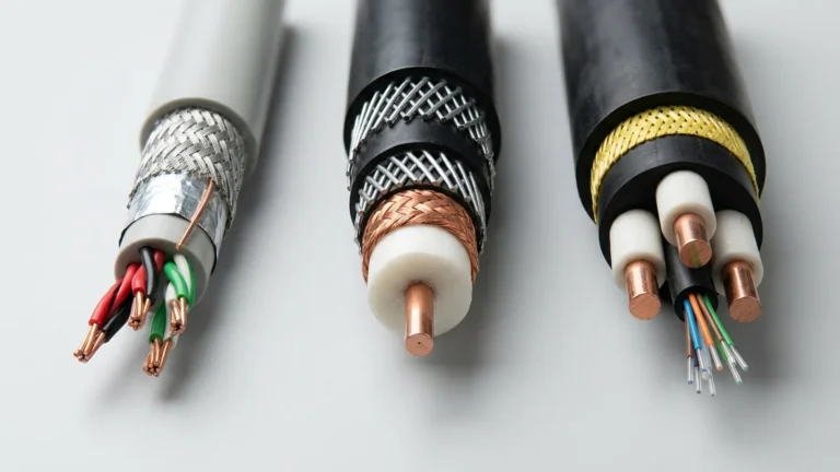
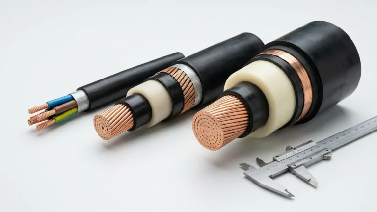
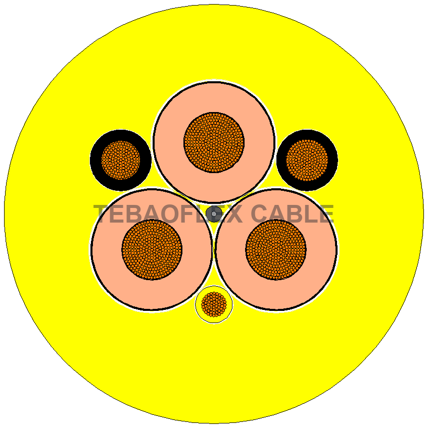
Identify material and section, insulation system, normal operating temperature, short-circuit temperature limit and cable standard for the exact build. Check phase conductors and the designated protective-earth (PE) conductor path. Where a metallic screen, sheath, armour or parallel earth element carries fault current, assess its own thermal and connection duty under the approved bonding arrangement. A screen is not automatically a compliant PE conductor merely because it is metallic.
How the I²t Cable Check Works
For a defined, short-duration adiabatic case, a common thermal screening relationship is I²t ≤ k²S², or S ≥ I√t / k. The left side represents the fault energy per ohm let through by the protective device; the right side represents the conductor’s permitted adiabatic thermal duty before insulation or contact damage occurs.
Adiabatic Screening Equation: I²t ≤ k²S² (or Minimum Area S ≥ I√t / k)
- I = Effective prospective fault current (RMS amperes, A) for the specified fault type and location
- t = Total protective-device clearing time (seconds, s), generally for short durations up to 5 s
- S = Nominal cross-sectional area of the conductor or metallic fault path (mm²)
- k = Material and temperature factor (A√s/mm²) determined by conductor metal, initial temperature (θ₀) and permitted final short-circuit temperature (θf)
Do not select k from insulation name alone. Conductor material, temperature assumptions, construction, connections and governing standard must fit the value. Schneider Electric’s Electrical Installation Guide presents the adiabatic relationship for the stated short-duration context and condition-specific k values. IEC 60949 starts with adiabatic current and then considers non-adiabatic heating; the simple equation is therefore not the entire cable-rating method.
| Fault-duty sequence | Design question | Evidence to retain |
|---|---|---|
| Fault begins | Which fault type and location produce the duty? | Fault-study case and prospective current |
| Protection detects it | Which device and setting operate? | Breaker/fuse model, settings and coordination study |
| Current flows until interruption | What is actual clearing time or total let-through I²t? | Manufacturer curve or validated calculation |
| Cable is assessed | Can every credited path tolerate the duty? | Approved cable drawing, material/temperature basis and calculations |
Worked screening example — not a cable approval
Assume a 25 mm² copper conductor in a specifically qualified 90°C-to-250°C EPR/XLPE case, where the cited guide gives k = 143 A√s/mm²:
- Conductor adiabatic limit (k²S²): (143 × 25)² = 12.78 million A²s (1.278 × 10⁷ A²s).
- Case A (10 kA fault cleared in 0.10 s): I²t = (10,000)² × 0.10 = 10.0 million A²s — below the 12.78 million A²s screening limit.
- Case B (10 kA fault cleared in 0.20 s): I²t = (10,000)² × 0.20 = 20.0 million A²s — exceeds the limit; doubling clearing time reverses the screening result without changing the conductor.
These simplified arithmetic cases are not a recommendation for a 25 mm² cable or a claim about any TEBAOFLEX product. The actual device may limit current, total clearing I²t may differ from I² × t, and the temperature pair may not apply to a proposed flexible cable or its accessories. Obtain product- and project-specific values before approval.
Which Standards and Temperature Limits Apply?
Voltage class and complete cable design determine the relevant temperature-limit reference. IEC 60724 gives guidance for cables rated 1 kV and 3 kV, while IEC 60986 addresses the 6–30 kV range. Both IEC standards evaluate conductor and metallic-sheath materials, connection methods, accessories and installation conditions alongside insulation.
| Insulation / Component System | Initial Temp (θ₀) | Short-Circuit Limit (θf) | Typical Copper k (A√s/mm²) | Application & Standard Context |
|---|---|---|---|---|
| EPR / HEPR / XLPE (Phase Core) | 90 °C | 250 °C | 143 | Standard reference for thermoset power cores (IEC 60724 / IEC 60364-5-54 condition) |
| Rubber / EPR (85 °C Rated Core) | 85 °C | 220 °C | 134 | Specific flexible rubber compounds where short-circuit ceiling is limited to 220 °C |
| PVC (Conductor ≤ 300 mm²) | 70 °C | 160 °C | 115 | General fixed control/power cables; lower thermal ceiling than thermoset EPR |
| Copper Screen / Armour / Sheath Contact | 60 °C – 80 °C | 160 °C – 200 °C | Build-specific | Often constrained by outer polychloroprene/PUR sheath contact or soldered/clamped terminations |
A short-circuit temperature on a product page is a starting point, not a standalone kA-for-one-second rating. For a documented cable family, see the (N)TSCGEWÖU MT medium-voltage reeling cable; request the build-specific conductor/earth drawing and short-circuit evidence for the chosen configuration.
Flexible, Trailing and Reeling Cables: Beyond the Equation
A moving cable adds mechanical and interface constraints beyond conductor heating. Confirm which phase, PE and screen elements remain continuous through reels, slip rings, couplers and terminations; whether the cable is rated for dynamic tensile and torsional duty; and whether electrodynamic forces during a fault could damage contacts or nearby supports.
For a reel-fed crane, the port and crane reeling-cable selection guide covers movement and routing; those checks complement short-circuit verification. For mining and tunneling trailing cables or ground-check systems, confirm the designated PE path and monitoring circuit separately. A ground-check pilot is not a substitute for the fault-current path.
Short-Circuit Withstand Checklist for a Cable RFQ
If a specification says only “10 kA for 1 s,” ask whether it denotes prospective current at the cable, a cable withstand requirement or a device rating. These are different statements. Send the fault study and device data with the proposed build instead of converting a kA label into an order code.
| Information to send | Why it is needed |
|---|---|
| Site country, adopted code and product standard | Establishes calculation and approval scope |
| Voltage, grounding and one-line diagram | Identifies fault types and current paths |
| Maximum and minimum fault current at the cable, with study basis | Checks severe duty and potentially slower protection operation |
| Breaker/fuse model, settings, curve or total clearing I²t | Determines actual disconnection and let-through |
| Phase, PE, screen and armour sections; bonding plan | Allows separate verification of each credited path |
| Operating and permissible short-circuit temperatures | Supports a justified k or other thermal method |
| Length, reel, roller and coupler details; movement duty | Checks continuity and accessory suitability |
| Required documentation and acceptance tests | Defines delivery and commissioning evidence |
Finish the Cable Selection
Begin with normal-load conductor selection, then verify voltage drop, short-circuit duty, protective-earth and screen paths, movement and terminations. TEBAOFLEX reviews proposed heavy-duty flexible rubber cable and port crane reeling cable constructions against customer conductor schedules and operating duty, while the project engineer retains fault-study, protection-coordination and local-code approval decisions.
Need Build-Specific Short-Circuit Data for Your Cable RFQ?
Share your conductor schedule, prospective fault current (kA), protective clearing time (s), and operating duty (reeling, festoon, or trailing). TEBAOFLEX engineers will provide documented phase, PE, and screen cross-sections alongside thermal limits for your project submittal.
Request Technical Review & Custom Cable Quote →Frequently Asked Questions
Is a cable rated 10 kA for one second if its conductor passes the I²t formula?
Not automatically. The formula is a thermal check under stated assumptions. Actual suitability also depends on the complete build, temperatures, all fault-current paths, terminations, protection and applicable standard.
Does a faster breaker let me choose a smaller cable?
Shorter verified clearing time can reduce thermal fault duty, but it does not remove ampacity, voltage-drop, mechanical, minimum-size or code requirements. Use exact device settings and let-through data.
Do phase conductors and PE need separate checks?
Yes. Their fault currents, areas, materials, temperature limits and connections may differ. A screen or armour needs separate assessment if credited with part of the fault current.
Can I apply one k value to every rubber or EPR cable?
No. Select k only for documented conductor material and initial/final temperature assumptions under the applicable method. Confirm actual cable construction and connection limits.
Source notes: IEC 60949 (thermally permissible currents and non-adiabatic effects); IEC 60724 (temperature-limit guidance for 1/3 kV cables); IEC 60986 (guidance for 6–30 kV cables); Schneider Electric Electrical Installation Guide (adiabatic relationship, example k conditions and electrodynamic considerations). Source links appear above. Technical scope reviewed 23 October 2026.