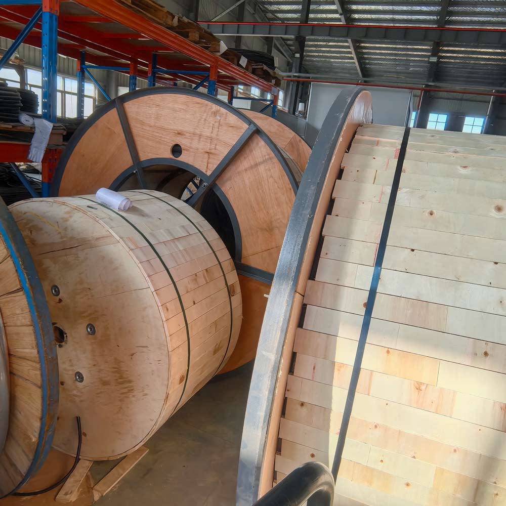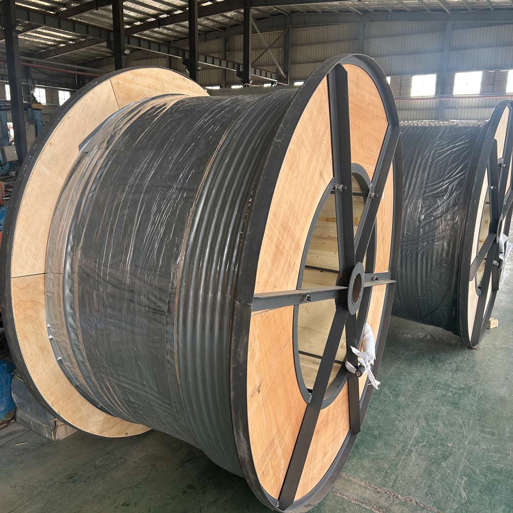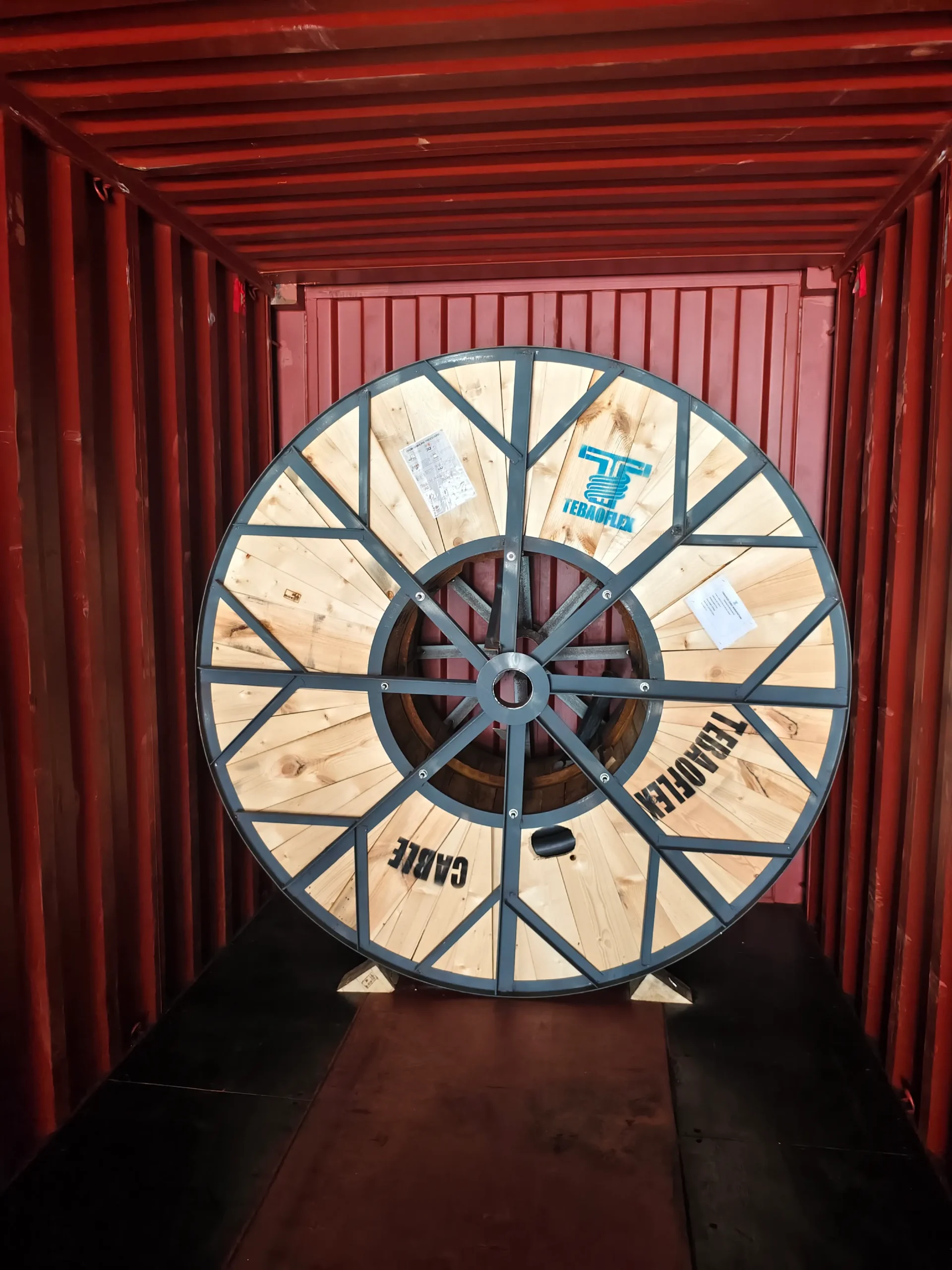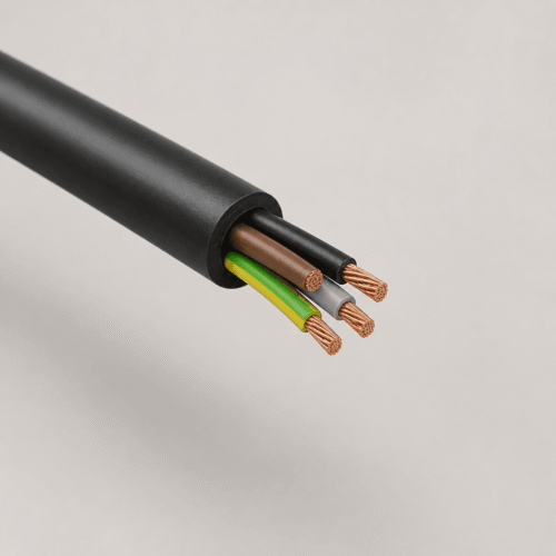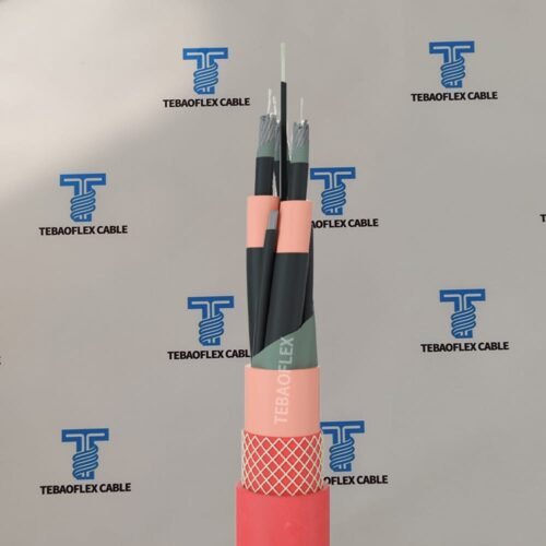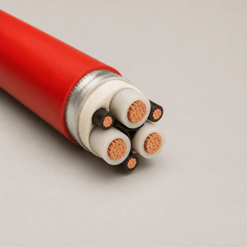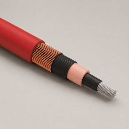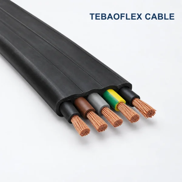
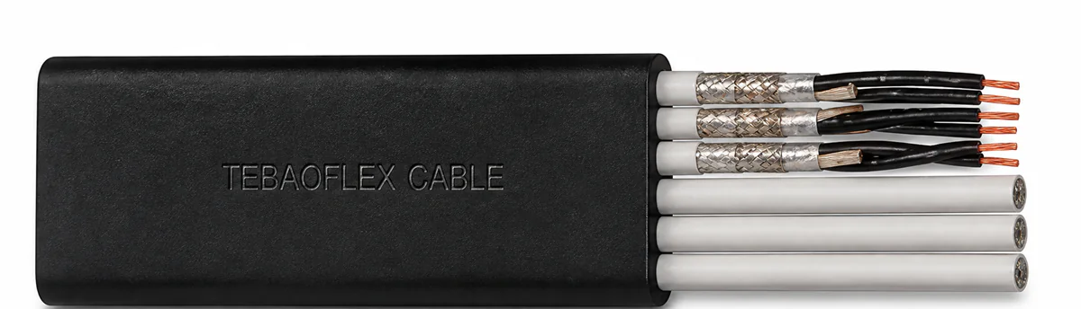
NGFLGOEU cable is a 300/500 V flat rubber power and control cable for festoon trolley systems and movable machine parts. Its parallel-core geometry is designed for frequent bending in one plane, with EPR insulation, a black chloroprene rubber sheath and a documented trolley speed up to 180 m/min.
TEBAOFLEX offers NGFLGOEU flat festoon cable in power, control and selected screened configurations from 1 mm² to 120 mm². Final dimensions, current capacity, bend radius, tensile load and documentation are confirmed against the ordered configuration and installation data before production.
NGFLGOEU Flat Festoon Cable at a Glance
| Selection point | Documented value |
|---|---|
| Cable type | Low-voltage flat festoon power and control cable |
| Rated voltage U0/U | 300/500 V (600 V) |
| Maximum AC operating voltage | 0.7/1.2 kV |
| Maximum DC operating voltage | 0.9/1.8 kV |
| AC test voltage | 2.5 kV for 5 minutes |
| Conductor temperature | +90°C maximum; +250°C short circuit |
| Ambient range | -50°C to +80°C fixed; -35°C to +80°C fully flexible |
| Maximum tensile load | 15 N/mm² |
| Festoon trolley speed | Up to 180 m/min |
| Motion | Frequent bending in one plane; not for gantry or reeling duty |
What Is NGFLGOEU Cable Used For?
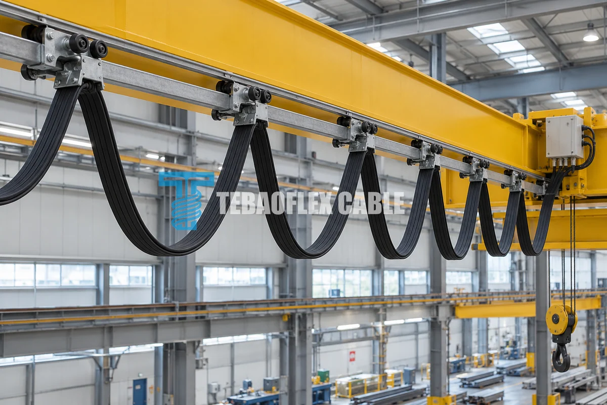
NGFLGOEU is used where a moving machine needs power or control circuits delivered through a supported festoon system. Common searches include NGFLGOEU flat cable, crane festoon cable, flat rubber cable, festoon trolley cable, overhead crane cable and material handling cable. The flat form keeps the cores in a parallel plane so the cable can form repeatable loops between trolley carriers.
Typical equipment includes overhead bridge cranes, transfer lines, travelling hoists, conveyor systems and other movable machinery with a properly engineered festoon track. The application must keep bending in one plane and support the cable at the trolley saddles. The documented construction is not intended as a reeling cable and should not be substituted for a gantry or reel duty without engineering review.
How Is the NGFLGOEU Flat Rubber Cable Constructed?
| Component | Construction | Engineering relevance |
|---|---|---|
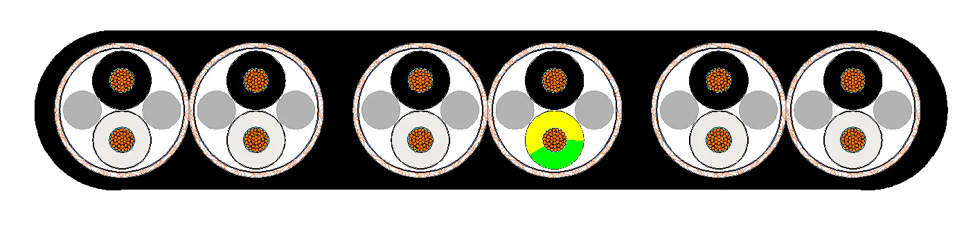
| Conductor | Electrolytic bare copper; Class 6 up to 25 mm² and Class 5 from 35 mm² | Provides flexibility for repeated festoon movement while supporting larger power sizes. |
| Insulation | EPR rubber compound 3GI3 | Electrical insulation for the documented voltage and temperature range. |
| Core identification | Up to 5 cores: green/yellow, black, blue, brown and grey; over 5 cores: black with white numbers | Supports installation and circuit identification. |
| Individual screen | Tinned copper braid, approximately 60% coverage; approximately 80% for twisted or shielded pairs | Available in the documented C and shielded-pair configurations where circuit screening is required. |
| Core arrangement | Cores in parallel; more than 12 cores arranged in parallel bundles | Creates the flat profile and controls one-plane bending. |
| Outer sheath | Black CR rubber compound 5GM3 | Provides the outer mechanical and environmental protection. |
Operating Characteristics and Environmental Performance
The documented cable is intended for indoor and outdoor use in dry, humid and wet rooms. It is described as resistant to oil under DIN VDE 0473-404 paragraph 10 and resistant to ozone, UV and moisture. These characteristics apply to the confirmed NGFLGOEU construction and do not replace a project review for chemical concentration, immersion, extreme abrasion or special fire-performance requirements.
| Performance item | Reference |
|---|---|
| Design standard | DIN VDE 0250-809 |
| Current capacity | DIN VDE 0298-4 |
| Minimum bending radius | According to DIN VDE 0298 Part 3 and the size-specific values below |
| Oil resistance | DIN VDE 0473-404 paragraph 10 |
| Weather resistance | Ozone, UV and moisture resistant |
| Installation environment | Indoor and outdoor; dry, humid and wet rooms |
NGFLGOEU Cable Sizes, Dimensions and Electrical Data
The following dimensional series is reproduced from the supplied TEBAOFLEX technical sheet. Dimensions and weights are nominal. R20 is conductor resistance at 20°C; current is the documented carrying capacity in free air; short-circuit current is the conductor short-circuit value. Select the exact configuration before using these values for design or quotation.
| Configuration | Cond. dia. max. mm | Height min. mm | Height max. mm | Width min. mm | Width max. mm | Bend radius min. mm | Weight kg/km | Tensile force max. N | R20 Ω/km | Current A | Short circuit kA |
|---|---|---|---|---|---|---|---|---|---|---|---|
| 3×1.5 | 1.5 | 5.7 | 6.2 | 11.7 | 12.5 | 19 | 130 | 68 | 13.3 | 24 | 0.21 |
| 4×1.5 | 1.5 | 5.7 | 6.2 | 15 | 15.8 | 19 | 170 | 90 | 13.3 | 24 | 0.21 |
| 5×1.5 | 1.5 | 5.5 | 6 | 18.5 | 20.1 | 18 | 210 | 113 | 13.3 | 24 | 0.21 |
| 7×1.5 | 1.5 | 5.5 | 6 | 25 | 26.8 | 18 | 280 | 158 | 13.3 | 24 | 0.21 |
| 8×1.5 | 1.5 | 5.5 | 6 | 27.5 | 29.3 | 18 | 310 | 180 | 13.3 | 24 | 0.21 |
| 10×1.5 | 1.5 | 6.2 | 6.7 | 35.5 | 37 | 20 | 440 | 225 | 13.3 | 24 | 0.21 |
| 12×1.5 | 1.5 | 6.3 | 6.8 | 42 | 43.5 | 20 | 530 | 270 | 13.3 | 24 | 0.21 |
| 24×1.5 | 1.5 | 11.5 | 12.3 | 51 | 53.2 | 62 | 1040 | 540 | 13.3 | 24 | 0.21 |
| 42×1.5 | 1.5 | 15.1 | 16.1 | 70.2 | 72.3 | 81 | 1920 | 945 | 13.3 | 24 | 0.21 |
| 4×2.5 | 2 | 6.8 | 7.3 | 18.5 | 19.5 | 22 | 260 | 150 | 7.98 | 32 | 0.36 |
| 5×2.5 | 2 | 6.6 | 7.4 | 22.9 | 24.6 | 22 | 320 | 188 | 7.98 | 32 | 0.36 |
| 7×2.5 | 2 | 6.8 | 7.4 | 31 | 32.8 | 22 | 440 | 263 | 7.98 | 32 | 0.36 |
| 8×2.5 | 2 | 6.8 | 7.4 | 34.1 | 35.9 | 22 | 490 | 300 | 7.98 | 32 | 0.36 |
| 10×2.5 | 2 | 7.4 | 8 | 43 | 45.3 | 24 | 660 | 375 | 7.98 | 32 | 0.36 |
| 12×2.5 | 2 | 7.4 | 8 | 50.6 | 53.5 | 24 | 780 | 450 | 7.98 | 32 | 0.36 |
| 24×2.5 | 2 | 14.8 | 15.6 | 65.4 | 68 | 78 | 1690 | 900 | 7.98 | 32 | 0.36 |
| 7x(3×1) | 1.3 | 8.7 | 10.3 | 49.3 | 51.8 | 41 | 770 | 315 | 19.5 | 19 | 0.14 |
| 4×4 | 2.8 | 8.4 | 8.9 | 22.5 | 23.5 | 36 | 390 | 240 | 4.95 | 43 | 0.57 |
| 4×6 | 3.5 | 9 | 9.5 | 25.4 | 26.9 | 38 | 500 | 360 | 3.3 | 56 | 0.86 |
| 4×10 | 4.5 | 10.5 | 11 | 30.1 | 32.6 | 44 | 750 | 600 | 1.91 | 78 | 1.43 |
| 4×16 | 5.6 | 12.1 | 12.9 | 36 | 37.5 | 65 | 1060 | 960 | 1.21 | 104 | 2.29 |
| 4×25 | 6.6 | 13.6 | 14.4 | 41.9 | 43.4 | 72 | 1500 | 1500 | 0.78 | 138 | 3.58 |
| 4×35 | 8.1 | 14.8 | 16.7 | 47 | 49.9 | 84 | 2040 | 2100 | 0.55 | 170 | 5.01 |
| 4×50 | 9.5 | 18 | 19 | 56 | 58 | 95 | 2830 | 3000 | 0.39 | 212 | 7.15 |
| 4×70 | 11.1 | 20.3 | 21.3 | 63.2 | 65.2 | 107 | 3820 | 4200 | 0.27 | 263 | 10.01 |
| 4×95 | 12.9 | 23.1 | 24.1 | 72.6 | 74.6 | 121 | 4930 | 5700 | 0.21 | 316 | 13.59 |
| 4×120 | 15 | 24.2 | 27.2 | 79.2 | 83.2 | 136 | 6220 | 7200 | 0.16 | 370 | 17.16 |
| 5×4 | 2.8 | 8.5 | 9 | 28.9 | 31.2 | 36 | 510 | 300 | 4.95 | 43 | 0.57 |
| 5×6 | 3.5 | 9.1 | 9.6 | 31.8 | 34.1 | 38 | 640 | 450 | 3.3 | 56 | 0.86 |
| 5×10 | 4.5 | 10.5 | 11.3 | 39.2 | 41.6 | 45 | 960 | 750 | 1.91 | 78 | 1.43 |
| 5×16 | 5.6 | 12.2 | 12.7 | 45.1 | 47.6 | 64 | 1360 | 1200 | 1.21 | 104 | 2.29 |
| 7×4 | 2.8 | 8.4 | 9 | 38.5 | 40.9 | 36 | 690 | 420 | 4.95 | 43 | 0.57 |
| 7×6 | 3.5 | 9 | 9.6 | 42.9 | 45.3 | 38 | 870 | 630 | 3.3 | 56 | 0.86 |
| 7×10 | 4.5 | 10.5 | 11.3 | 53 | 55.9 | 45 | 1320 | 1050 | 1.91 | 78 | 1.43 |
| 7×16 | 5.6 | 12.6 | 13.4 | 60.7 | 63.9 | 67 | 1990 | 1680 | 1.21 | 104 | 2.29 |
| 7×25 | 6.6 | 14.8 | 15.6 | 72.6 | 75.9 | 78 | 2820 | 2625 | 0.78 | 138 | 3.58 |
| 7×35 | 8.1 | 16.4 | 17.4 | 83.7 | 87 | 87 | 3820 | 3675 | 0.55 | 170 | 5.01 |
| 12×1(C) | 1.3 | 6.6 | 7.1 | 48.2 | 51.3 | 21 | 660 | 180 | 19.5 | 19 | 0.14 |
| 4×1.5(C) | 1.5 | 6.8 | 7.4 | 18.5 | 19.5 | 22 | 250 | 90 | 13.3 | 24 | 0.21 |
| 8×1.5(C) | 1.5 | 6.8 | 7.4 | 35.1 | 35.1 | 22 | 510 | 180 | 13.3 | 24 | 0.21 |
| 12×1.5(C) | 1.5 | 7.4 | 8 | 51.7 | 55 | 24 | 780 | 270 | 13.3 | 24 | 0.21 |
How Do You Select the Correct Flat Festoon Cable?
| RFQ input | Why it matters |
|---|---|
| Power and control circuits | Determines the core count, conductor sizes and whether screened pairs or individually screened cores are required. |
| Travel distance and speed | Allows trolley spacing, loop depth, cable reserve and the stated 180 m/min speed limit to be checked. |
| Bending plane and motion | Confirms that the installation is a supported festoon system with bending in one plane rather than reeling or gantry motion. |
| Trolley saddle geometry | Must suit the finished cable width, height, minimum bend radius and permissible tensile force. |
| Ambient and exposure | Confirms temperature, indoor or outdoor use, humidity, water, UV, ozone, oil and any chemical exposure. |
| Electrical design | Defines voltage, current, voltage drop, short-circuit duty and conductor temperature for the selected size. |
| Documentation | Identifies the required drawings, tests, inspection records, marking and project-specific approvals before production. |
Installation Limits and Engineering Notes
- Use NGFLGOEU in a supported festoon trolley system with bending in one plane only.
- Do not use this construction as a random-winding, monospiral, spring reel or motorized reeling cable.
- Do not treat the 180 m/min reference as a universal system guarantee; trolley spacing, acceleration, loop depth and installation geometry remain part of the complete design.
- Observe the size-specific minimum bend radius and maximum tensile force in the dimensional table.
- Protect the cable from twisting, side pull, sharp trolley edges, crushing and uncontrolled impact.
- Confirm current capacity and short-circuit duty for the actual ambient temperature, grouping, ventilation and duty cycle.
Custom NGFLGOEU Cable from TEBAOFLEX
TEBAOFLEX can review power, control and screened NGFLGOEU configurations for the target crane or material-handling system. Customisation can include the documented core and conductor combinations, screened circuits, cable length, sheath marking, cut lengths, reel length and export packaging. Send the circuit schedule, trolley-system drawing, travel speed, loop depth, travel distance, ambient conditions and quantity so the technical team can confirm the cable and installation data.
Related Festoon and Crane Cable Options
- (N)GFLCGÖU screened flat festoon cable for applications that require a different screened construction.
- Flat PNCT rubber cable for selected port and crane applications after duty review.
- D12YC11Y-J screened PUR festoon cable where a round PUR construction is required.
- Port, crane and festoon cable range for related mobile-equipment cables.
Frequently Asked Questions
What voltage is NGFLGOEU cable rated for?
The documented rated voltage U0/U is 300/500 V (600 V), with maximum AC operating voltage of 0.7/1.2 kV and maximum DC operating voltage of 0.9/1.8 kV.
Is NGFLGOEU suitable for crane festoon systems?
Yes. It is designed for festoon trolley systems and movable machine parts with frequent bending in one plane. The documented trolley speed is up to 180 m/min, subject to the complete system design.
Can NGFLGOEU be used on cable reels?
No. The supplied technical sheet states that this flat cable is not for gantry or reeling duty. Select a purpose-designed reeling cable for reel systems.
What is the temperature range?
The fixed ambient range is -50°C to +80°C and the fully flexible range is -35°C to +80°C. Maximum conductor temperature is +90°C.
Are screened versions available?
The documented range includes selected C constructions and screened or twisted pairs using tinned copper braid. Confirm the circuit schedule and screening requirement before quotation.
What details are needed for a quotation?
Provide the required configuration, voltage, current, travel distance, maximum speed, trolley spacing, loop depth, minimum installation temperature, outdoor exposure, cable length, quantity and documentation requirements.
Send Your NGFLGOEU Cable Requirements
Send the crane or festoon-system drawing, conductor configuration, travel data, installation environment, required length and quantity. TEBAOFLEX will review the size-specific dimensions, bending radius, tensile load and production requirements before quotation.