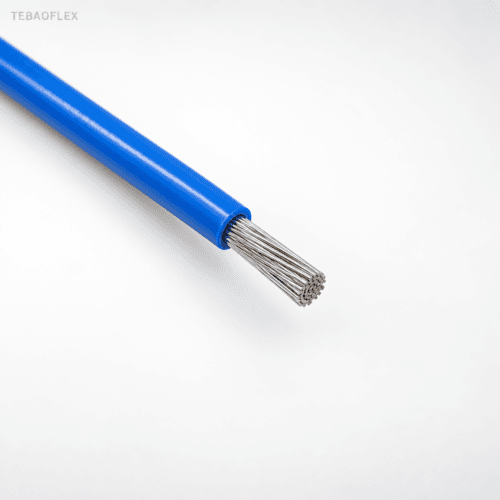
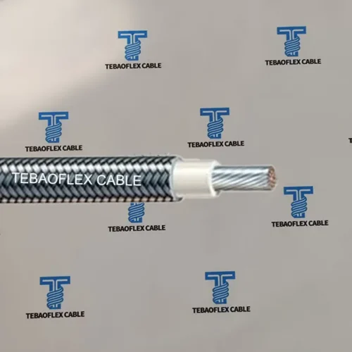
TEBAOFLEX UL 3590 Silicone Rubber Heating Wire is a slim-profile 300 V, 200°C flexible resistance-heating element engineered around a heat-resistant glass-fiber support core (≤ 1.30 mm), a precision spirally wound resistance alloy filament, and a ≥ 0.38 mm extruded silicone rubber wall (nominal 2.00 ± 0.10 mm OD, or specified fiberglass braid jacket). Unlike ordinary copper power leads, it converts current directly into uniform linear heat across custom design values from 0.5 Ω to 12,000 Ω (±7%).
1. Flexible Heating Application Scope & Heating Wire Comparison
Thin textile and pad heaters require a supple, small-diameter heating element that distributes heat evenly without stiff wire ridges or brittle alloy fatigue. Documented and engineering-reviewed applications for UL 3590 include:
- Electric Blankets & Underblankets: Slim
2.00 mmnominal outer diameter routes smoothly through quilted textile channels while maintaining flexible drape and2,000 VACdielectric strength. - Electric Carpets, Floor Mats & Heated Cushions: Distributed low-watt-density serpentine loops paired with NTC thermistors, thermostats, and over-temperature thermal cutoffs.
- Reviewed Appliance & Enclosure Pad Heaters: Custom low-profile warming pads, battery/instrument anti-condensation elements, and commercial food-warming panels after complete electrical, thermal, and safety validation.
Compare related heating elements and high-temperature lead wires across our high-temperature and specialty cable range:
| TEBAOFLEX Heating / High-Temp Wire | Voltage / Temp | Wall & Typical OD | Primary Engineering Role |
|---|---|---|---|
| UL 3590 Heating Wire (This Page) | 300 V / 200°C | ≥ 0.38 mm | 2.00 ± 0.10 mm | Slim spiral-wound heating wire for blankets, carpets & thin pads |
| UL 3323 Silicone Heating Wire | 300 V / 200°C | ≥ 0.76 mm | ~2.5 – 3.2 mm | Heavier-wall silicone resistance wire for refrigeration defrost & drain heaters |
| HTS-6 Self-Regulating Heating Cable | 120–277 V / 65–85°C | PTC Matrix + Tinned Cu Braid | 6 W/ft self-regulating freeze protection for roofs, gutters & pipes |
| UL 3122 Silicone Fiberglass Lead Wire | 300 V / 200°C | Silicone + Glass Braid Copper | Non-heating copper cold-lead termination wire for heater assemblies |
| UL 3135 / 3367 Silicone Hook-Up Wire | 300–600 V / 200°C | Extruded Silicone Copper | Flexible copper power supply lead connecting controller to heater element |
| UL 5334 450°C Mica Fiberglass Wire | 300 V / 450°C | Mica Tape + Fiberglass Copper | Ultra-high-temperature furnace, kiln & cartridge-heater cold leads |
2. 3-Layer Spiral Resistance Construction & Outer Jacket Comparison
Built on precision helical winding equipment to maintain uniform ohms-per-meter pitch and eliminate localized hot spots:
≤ 1.30 mm diameter) providing dimensional stability, high thermal endurance, and flex-fatigue relief for the fine alloy winding.CuNi, Constantan, or Nickel-Chromium NiCr 80/20 selected by target resistance) helically wound at controlled pitch around the glass core.≥ 0.38 mm average wall, nominal 2.00 ± 0.10 mm finished OD in Red, White, Brown, or custom color) OR a specified fiberglass braid outer jacket depending on the engineered heater design.Silicone Rubber Insulation vs. Fiberglass Braid Outer Construction
| Outer Construction Variant | Dielectric & Mechanical Behavior | Mandatory Engineering Checks Before Ordering |
|---|---|---|
| Extruded Silicone Rubber Insulation | Closed, flexible elastomeric dielectric barrier; smooth routing inside quilted blankets, carpets & bonded silicone pads | Confirm wall thickness (≥ 0.38 mm), color, minimum bend radius, humid/splash exposure & cold-lead splice encapsulation |
| Fiberglass Braid Jacket | Porous high-temperature textile sleeve for dry-air frames, ceramic supports & specialized industrial heater cartridges | Not moisture-sealed; confirm varnish/silicone impregnation, abrasion clearance & primary/secondary insulation of final appliance |
3. Electrical, Dimensional & Thermal Sizing Specifications
For initial resistive heater sizing, estimate active power from P = V² / R (where V is supply voltage and R is total element resistance in ohms), and verify linear watt density W/m = P / L against substrate heat dissipation:
| Parameter | Referenced Specification | Engineering & Safety Verification Note |
|---|---|---|
| Rated Voltage | 300 V AC max | Completed assembly must match controller, connector & end-product voltage limits |
| Rated Temperature | 200°C | Keep linear watt density typically ≤ 10–25 W/m in textiles to prevent hot spots |
| Dielectric Withstand | 2,000 VAC for 1 minute | Confirm routine spark/dielectric test method & lot report at enquiry stage |
| Glass-Fiber Core Diameter | ≤ 1.30 mm | Non-conductive mechanical carrier; carries tensile routing load during winding |
| Average Insulation Wall | ≥ 0.38 mm | Applies to referenced extruded silicone construction |
| Finished Outer Diameter | 2.00 ± 0.10 mm | Custom thicker walls (e.g., 2.4–3.2 mm per UL 3323) available on review |
| Min. Insulation Resistance | ≥ 15 MΩ/km | Measured at 20°C on extruded silicone-insulated construction |
| Custom Resistance & Tolerance | 0.5 to 12,000 Ω (±7%) | Specify plainly whether target ohms apply per meter (Ω/m) or per cut heater piece (Ω) |
Safety, Control & Compliance Boundary: UL 3590 style reference defines wire construction and thermal class; no third-party UL file number is implied unless explicitly confirmed on your quotation. Never connect resistance heating wire directly across mains power without a reviewed heater layout, closed-loop temperature controller, and independent over-temperature thermal cutoff. Do not use in liquid immersion, outdoor wet exposure, or direct human-contact medical/bedding products without full end-appliance safety certification.
4. Representative UL 3590 Linear Resistance & Alloy Selection Schedule
Because every OEM heater combines a distinct voltage (12V / 24V DC or 100V / 120V / 230V AC) and circuit length, TEBAOFLEX winds UL 3590 to order. The schedule below illustrates typical linear resistance bands at 2.00 ± 0.10 mm finished silicone OD (all part codes use clean standard designations):
| Part Designation | Nominal Linear Resistance (Ω/m @20°C) | Tolerance | Typical Alloy Family | Glass Core Ø (mm) | Finished Silicone OD (mm) | Typical Heater Circuit Examples |
|---|---|---|---|---|---|---|
| UL3590-SIL-1R0 | 0.5 – 2.0 Ω/m | ±7% | CuNi Low-Ohm Alloy | ≤ 1.30 | 2.00 ± 0.10 | 12V / 24V DC seat, cushion & battery pads |
| UL3590-SIL-5R0 | 2.1 – 8.0 Ω/m | ±7% | CuNi23 / CuNi30 | ≤ 1.30 | 2.00 ± 0.10 | 24V – 48V warming mats & long-loop AC elements |
| UL3590-SIL-15R | 8.1 – 25 Ω/m | ±7% | CuNi44 (Constantan) | ≤ 1.30 | 2.00 ± 0.10 | 110V / 120V AC electric carpets & large blankets |
| UL3590-SIL-40R | 26 – 60 Ω/m | ±7% | CuNi44 / NiCr Alloy | ≤ 1.30 | 2.00 ± 0.10 | 120V / 230V AC dual-zone electric blankets |
| UL3590-SIL-100R | 61 – 150 Ω/m | ±7% | NiCr 80/20 | ≤ 1.30 | 2.00 ± 0.10 | 220V – 240V AC single/double underblankets |
| UL3590-SIL-250R | 151 – 350 Ω/m | ±7% | NiCr 80/20 Fine Pitch | ≤ 1.30 | 2.00 ± 0.10 | 230V AC compact foot warmers & heating pads |
| UL3590-SIL-500R | 351 – 800+ Ω/m (up to 12 kΩ total) | ±7% | NiCr / FeCrAl Fine Pitch | ≤ 1.30 | 2.00 ± 0.10 | Short-length 230V AC low-wattage warming strips |
| UL3590-FGB-CUSTOM | 0.5 – 12,000 Ω (Design-Specific) | ±7% | CuNi / NiCr + Glass Braid | ≤ 1.30 | Project-Confirmed | Dry-air braided textile heater frames |
5. Frequently Asked Engineering Questions & Custom RFQ
How does UL 3590 fiberglass-core heating wire differ from ordinary copper hook-up wire?
Unlike low-resistance copper hook-up leads designed to minimize voltage drop, UL 3590 is an active resistive heating element. A calibrated resistance-alloy filament is helically wound around a non-conductive glass-fiber support core so electrical current converts directly into uniform heat along the wire length.
What is the difference between UL 3590 and UL 3323 silicone rubber heating wires?
Both are 300 V, 200°C spiral-wound fiberglass-core heating wires, but referenced UL 3590 uses a slim ≥ 0.38 mm wall (2.00 ± 0.10 mm finished OD, or optional fiberglass braid) suited for flexible blankets and carpets, whereas UL 3323 uses a heavier ≥ 0.76 mm silicone wall (~2.5–3.2 mm OD) for commercial defrost and drain heaters.
What resistance range and tolerance can TEBAOFLEX manufacture in UL 3590?
Referenced design values span 0.5 to 12,000 Ω (specified either as linear resistance in Ω/m or total cut-piece resistance in Ω) at ±7% tolerance. Achievable values depend on alloy selection, winding pitch, voltage, active length, and safe linear watt density.
Should I specify extruded silicone rubber insulation or a fiberglass braid jacket?
Choose extruded silicone rubber when you need a closed, flexible dielectric surface inside blankets, carpets, or pads. Choose a fiberglass braid jacket only for dry-air heater frames where secondary electrical insulation and moisture protection are engineered into the enclosure.
How do I calculate required resistance from supply voltage and target wattage?
Estimate total element resistance from R = V² / P and linear resistance from Rlinear = R / L. Always validate linear watt density (W/m), thermal contact materials, thermostat regulation, and thermal-cutoff protection on physical prototypes.
What project details are needed to receive a confirmed UL 3590 quotation?
Provide supply voltage, target resistance (specify Ω/m vs. total Ω) or wattage, active heated length, target temperature, duty cycle, outer construction (silicone rubber vs. fiberglass braid), color, spool or pre-cut cold-lead termination needs, and order quantity.
Engineer Your Custom UL 3590 200°C Silicone Heating Wire
Send your operating voltage, target ohms/meter or total wattage, active element length, target surface temperature, silicone color or fiberglass braid choice, and order volume. TEBAOFLEX engineers review alloy pitch and quote within 24 hours.