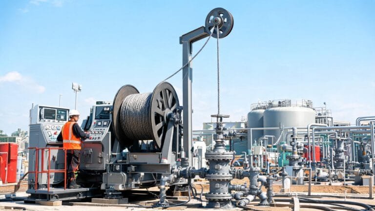
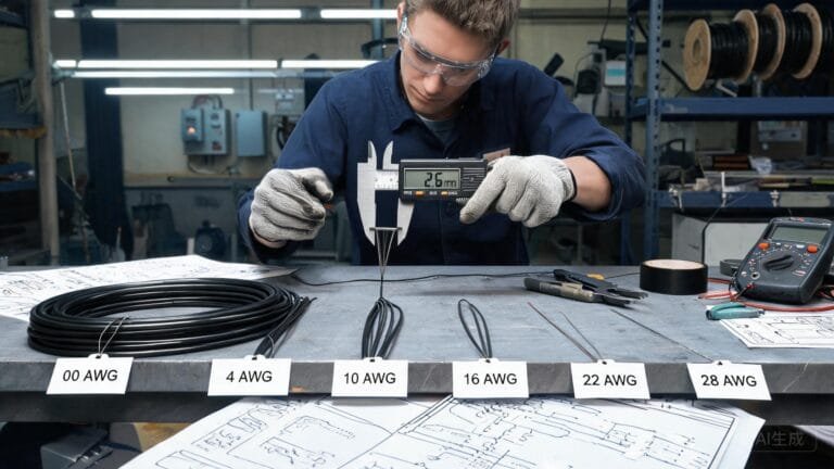
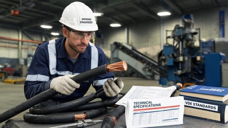
Ground-check selection for a Type G-GC 2 kV mining cable begins with the protection system—not simply with the cable designation. Define the power circuit, grounding arrangement, continuity-monitoring method and connector interfaces before requesting a final construction.
What ground-check selection is intended to protect
On a resistance-grounded mining power system, the grounding path and its continuity-monitoring circuit are part of the overall protection design. In its technical guidance, the U.S. Mine Safety and Health Administration (MSHA) explains that ground-check monitors continuously monitor the continuity of the grounding conductor on trailing-cable systems and can open the feeding breaker when continuity is lost. The exact legal and technical requirements depend on the mine, jurisdiction, system voltage and approved equipment.
That is why a ground-check conductor or pilot arrangement should not be treated as a substitute for the equipment grounding conductor. The system designer must define the complete monitored path, including the monitor or relay, the cable arrangement, couplers, splices and the machine frame connection.
What the listed Type G-GC construction confirms
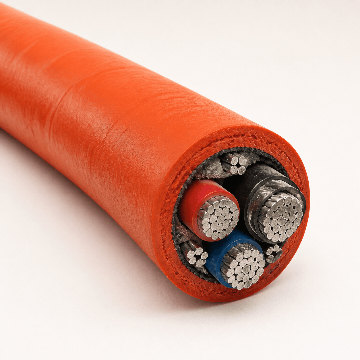
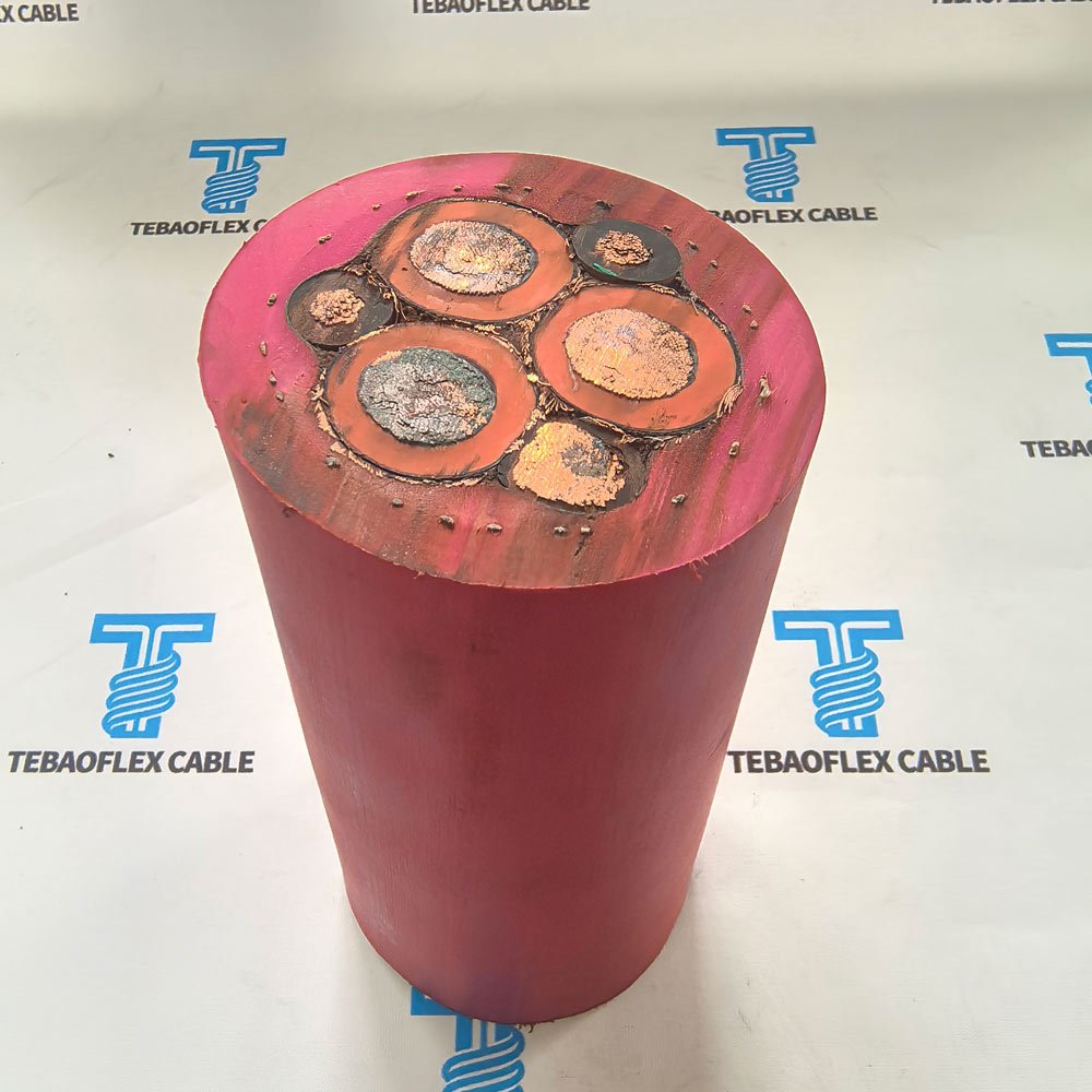
The TEBAOFLEX Type G-GC 2kV Mining Power Cable is listed for flexible power connections on mining equipment and mobile industrial machinery. Its published construction includes fine-stranded tinned-copper conductors, EPR insulation and an extra heavy-duty reinforced TSE jacket. The listing identifies abrasion, impact, vibration, flexing and tension as important design considerations.
The product page specifically asks customers to confirm the grounding configuration before ordering. It does not publish one universal ground-check-core quantity or cross-section for every project. State the required ground-check arrangement in the RFQ and have the supplied configuration reviewed against the protection-system documentation.
Ground-check information to put in the RFQ
| RFQ item | Why it matters | What to provide |
|---|---|---|
| System voltage | Confirms the cable voltage class matches the supply. | State the required 2,000 V system rating and applicable project documents. |
| Power conductors | Determines current-carrying construction and termination interfaces. | Conductor size, three-phase load, length, duty cycle and voltage-drop criteria. |
| Grounding configuration | The monitored grounding path must match the protection design. | Required grounding-conductor arrangement, ground-check / pilot requirement and termination mapping. |
| Monitor and connectors | Continuity protection depends on compatible system components. | Monitor or relay details, coupler model, pinout, terminator requirements and any approved splice method. |
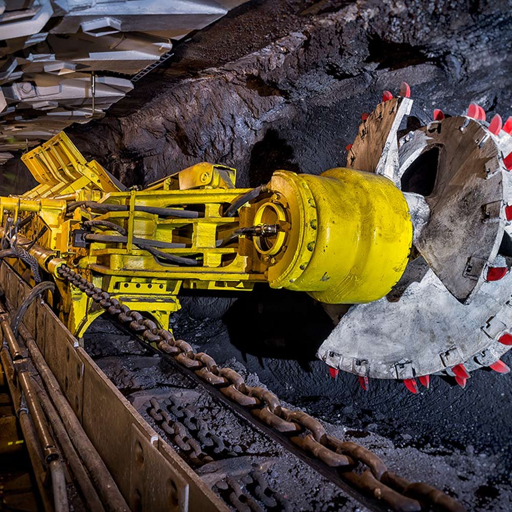
| Mechanical route | Mobile mining duty can impose abrasion, impact, tension and flexing. | Equipment type, travel path, reel or drag duty, bend points, clamps and expected movement. |
| Environment | Jacket and installation details must suit the actual exposure. | Temperature, water, oil, ozone, chemicals, rock contact and cleaning exposure. |
Use the cable rating as a starting point
The published Type G-GC listing gives a 2,000 V rating, EPR insulation, a reinforced TSE outer jacket, a −40°C cold-temperature rating and ICEA S-75-381 as a design reference. Its listed configurations use three power conductors, with conductor sizes from 8 AWG through 500 kcmil. These facts help establish the power-cable portion of the request, but they do not determine the complete ground-check circuit on their own.
Review the final cable construction alongside the monitor, couplers and equipment documentation. If a cable is repaired or spliced, the continuity of every required component should be preserved in accordance with the approved procedure. Do not rely on a visual jacket inspection as evidence that the protective circuit has been verified.
Separate the two selection decisions
First, select the power-cable construction: voltage rating, conductor size, length, flexible duty and jacket exposure. Then confirm the grounding and ground-check arrangement as part of the complete protection system. Combining the two decisions in a single, complete RFQ helps TEBAOFLEX review the required Type G-GC configuration before quotation.
For related cable applications, see the SHD-GC Mining Cable and the TEBAOFLEX industrial cable range. For documentation support, review TEBAOFLEX cable certifications, test reports and laboratory support.
Frequently asked questions
Does ground check replace the grounding conductor?
No. The monitored ground-check or pilot arrangement is part of a system that checks grounding continuity. The grounding conductor and the ground-check function must both match the approved system design.
Does every Type G-GC cable have the same ground-check-core configuration?
Do not assume this. The published TEBAOFLEX Type G-GC page requires the grounding configuration to be specified. Confirm the required construction, conductor details and terminations for the actual project.
What Type G-GC information is already listed?
The published product is rated 2,000 V and uses fine-stranded tinned copper, EPR insulation and a reinforced TSE jacket. It is intended for demanding flexible mining and mobile-industrial duty.
What should be checked after installation or repair?
Follow the mine’s approved safety, commissioning and maintenance procedures for the complete grounding and continuity-monitoring system. Cable splices and connectors must preserve the required electrical paths.
Request a ground-check-ready cable review
Send TEBAOFLEX your Type G-GC cable requirements, including voltage, conductor size, length, equipment, route, connector details and ground-check configuration. We can review the requested construction before quotation.