An airport lighting primary cable carries the series circuit between a constant-current regulator (CCR) and isolating transformers serving airfield lights. When comparing 2 kV and 5 kV systems, do not assume that the system designation is identical to the cable’s Uo/U rating: the project circuit, local standard, installation method and approved product construction must all be checked together.
How an airport lighting primary circuit works
In a typical airfield series circuit, the CCR supplies the primary circuit, which runs through the airport lighting primary cable to isolating transformers and connected light fittings. The cable selection must support the complete circuit arrangement, including route, joints, terminations and maintenance access—not only the light fixture location.
The FAA’s AC 150/5345-7F specifies L-824 underground electrical cable for airport-lighting circuits. Its related installation guidance describes conditions for 5 kV L-824 cable in airfield-lighting series circuits. Those FAA documents are an important U.S. reference, but a global project must follow its own contract, airport authority and applicable local requirements.

2 kV vs 5 kV: record the right value
A selection request should identify the actual circuit designation and the required cable rating separately. “2 kV” or “5 kV” may be used in a project or standard context, while the cable data sheet expresses its voltage rating in its own Uo/U format. These values cannot be treated as interchangeable without confirming the intended standard and the circuit design.
For example, the confirmed RG7H1R Airport Lighting Primary Cable listing is rated 3.6/6 kV and designed for airfield series circuits between CCRs and isolating transformers. It is not appropriate to relabel that product as “2 kV” or “5 kV” solely from a general project description. Instead, submit the system requirement, applicable standard and required cable Uo/U for review.
| Item to distinguish | What to confirm | Why it matters |
|---|---|---|
| Circuit requirement | Project circuit designation, CCR output and series-circuit design | Sets the electrical application to be served. |
| Cable rating | Required Uo/U rating from the approved cable specification | Confirms the cable construction being evaluated. |
| Standard or authority | FAA L-824 where applicable, or the stated local/project standard | Prevents applying a reference outside its intended scope. |
| Installation method | Direct burial, conduit, tray or other approved route | Changes mechanical protection and installation checks. |
| Terminations and joints | Transformer, connector and splice details | Ensures the complete circuit is specified. |
Construction and installation checks for RG7H1R
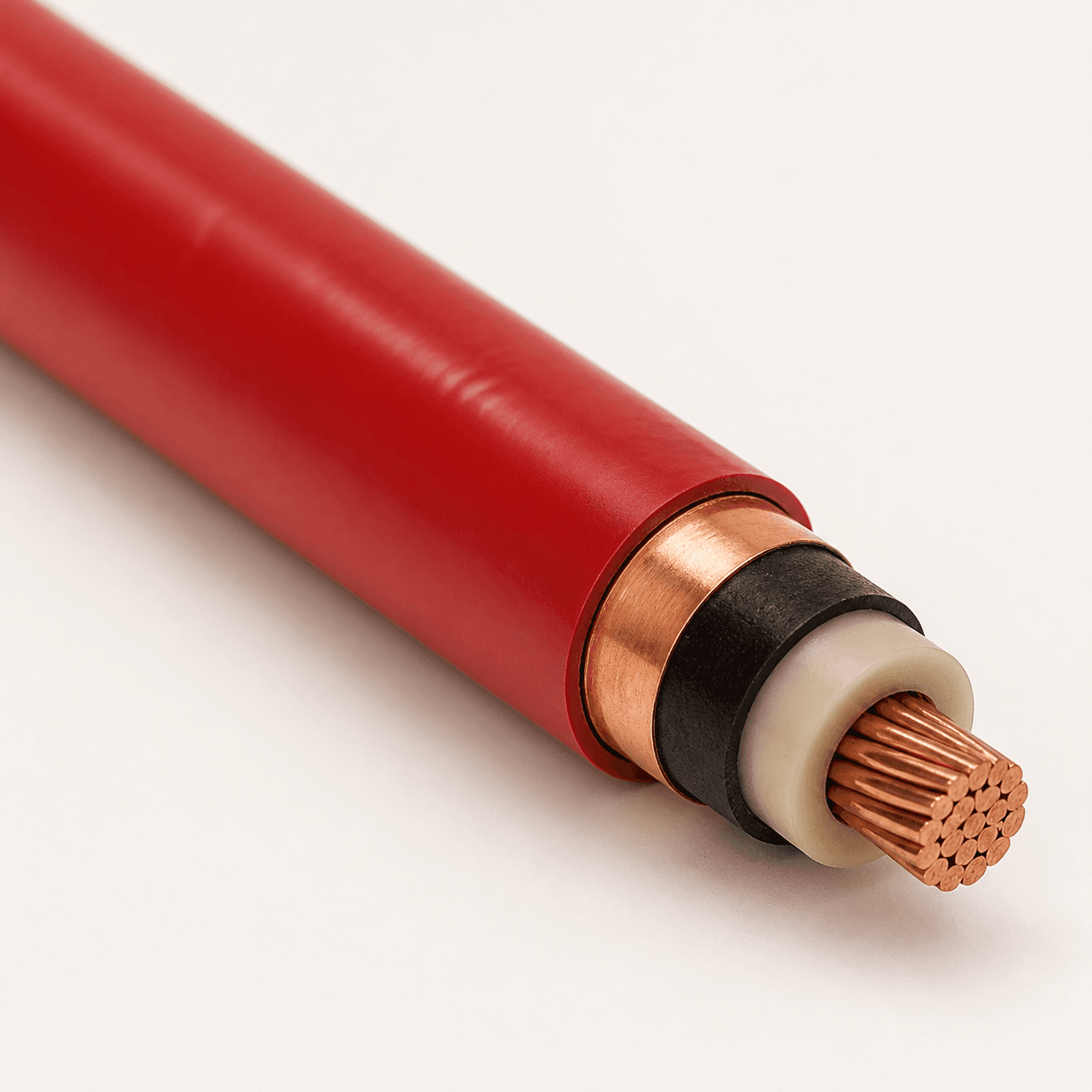
The listed RG7H1R construction uses a compact stranded bare copper conductor, G7-type rubber insulation, semi-conductive layers, bare copper tape shield and a red PVC sheath. Before ordering, verify the conductor size, route length and project requirements. The product listing specifies a minimum bend radius of 15 times the overall diameter; this must be allowed for in the actual route and at terminations.
Use the red sheath as a circuit-identification feature only within the approved airport installation practice. It does not replace cable marking, route records, warning systems or the project’s electrical safety procedures.
What to include in an airport lighting cable RFQ
- Airport project location, governing standard and approval requirements.
- CCR and primary-series-circuit information, including the specified system requirement.
- Required cable Uo/U rating, conductor size and total route length.
- Installation route, burial or conduit method, bend locations and joint details.
- Transformer, connector and splice information, together with required delivery documentation.
For supporting documentation, see TEBAOFLEX cable certifications, test reports and laboratory support. For wider project context, review Industrial Cable Applications.
Common selection mistakes
- Equating a project voltage label with cable Uo/U. Confirm both values separately.
- Copying a previous cable reference without checking the installation route. Installation method and termination details can change.
- Using a general power cable in place of a screened primary airfield cable. The primary circuit requires a documented construction and application review.
- Omitting joints, transformers and connectors from the RFQ. These parts determine the practical circuit interface.
Frequently asked questions
What does an airport lighting primary cable connect?
It connects components of the airfield series circuit, including the route from the CCR to isolating transformers, according to the approved design.
Is 5 kV the same as a 3.6/6 kV Uo/U cable rating?
No. They may appear in different technical contexts. Confirm the project circuit requirement, standard and cable data sheet before selection.
Can RG7H1R be used for every airfield lighting project?
No. Its confirmed product data should be checked against the project’s required rating, installation method, conductor size and standard.
Why is shielding included in a primary cable?
The listed RG7H1R construction includes semi-conductive layers and bare copper tape shielding. Confirm the complete approved construction rather than changing components independently.
How can TEBAOFLEX help with the selection?
Send your airport lighting cable requirements, including circuit, Uo/U, length, route and standard details, for a technical review.
Specify the circuit and the cable as one system
The correct 2 kV vs 5 kV decision starts with accurate circuit information, then checks the cable’s documented Uo/U rating, construction and installation route. TEBAOFLEX can help align those inputs with the RG7H1R airport lighting primary cable configuration before quotation.