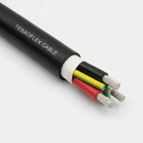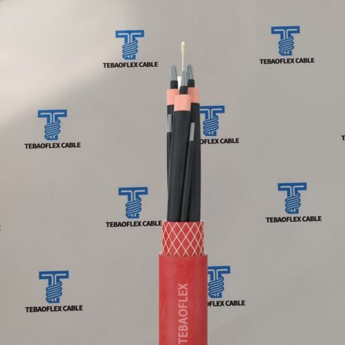
Application & Operating Conditions
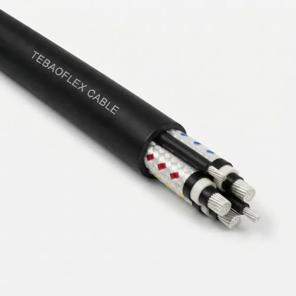
AS/NZS 1802 Type 240 is a general-use composite screened rubber mining feeder cable (1.1/1.1 kV to 11/11 kV) incorporating three separate interstitial pilot conductors. By replacing a single small central pilot with three dedicated elastomer-covered pilots (up to 35.7 mm²), Type 240 enables extended underground feeder runs without exceeding pilot control relay resistance limits.
Long-Distance Gate-End Feeders
Engineered for extended feeder circuits between underground substations/transformers and gate-end boxes (DCBs) where single-pilot cables suffer nuisance pilot-circuit trips due to loop resistance.
Dewatering Pumps & Continuous Miners
Delivers composite-screened phase fault protection and multi-pilot control/earth-continuity monitoring for high-head mine dewatering pumps, ventilation fans, and mobile mining machinery.
Submerged, Oily & C1 Flame Duty
Heavy-duty HD-85-PCP outer sheath (with optional reinforced sheath on request) withstands mine water immersion, hydraulic oils, rock abrasion, and C1 flame propagation in free air or ducts.
Why Specify Type 240 Over Type 209? Both cables use identical composite tinned-copper/polyester phase earth screens, but Type 240 replaces the single central pilot with three interstitial pilots (1–35.7 mm²) that can be paralleled to slash pilot-loop resistance on long underground runs or assigned to separate control/monitoring circuits.
Cable Construction (AS/NZS 1802 Type 240)
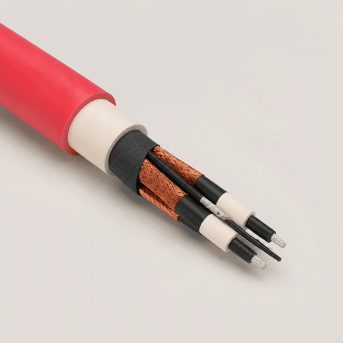
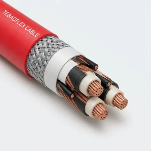
Type 240 combines three individually composite-screened tinned copper phase cores with three elastomer-covered interstitial pilot cores, incorporating voltage-graded semiconductive stress control at 3.3 kV and above inside a heavy-duty HD-85-PCP sheath.
| Layer / Component | Material & AS/NZS 1802 Specification |
|---|---|
| 1. Phase Conductors | Flexible stranded tinned annealed copper, three phase cores (6–300 mm²) |
| 2. Conductor Separator / Screen | Polyester tape for 1.1/1.1 kV (Type 240.1); extruded semi-conductive screen for 3.3 kV, 6.6 kV, and 11 kV |
| 3. Insulation | Ethylene-propylene rubber compound (R-EP-90 EPR): 1.5–3.0 mm (1.1 kV), 3.0 mm (3.3 kV), 5.0 mm (6.6 kV), 7.6 mm (11 kV) |
| 4. Insulation Tape / Screen | Proofed textile tape for 1.1/1.1 kV; semi-conductive screen for 3.3 kV and above |
| 5. Composite Earth Screen | Composite braid of tinned annealed copper wire and polyester yarn over each phase core (8.2–77 mm²) with red, white, and blue braid tracers |
| 6. Three Pilot Cores | Three separate pilot conductors laid in the outer interstitial cavities, each elastomer covered and proofed taped (1–35.7 mm²) |
| 7. Outer Sheath | Heavy-duty HD-85-PCP polychloroprene elastomer sheath (3.8–11.3 mm wall); reinforced sheath available on request |
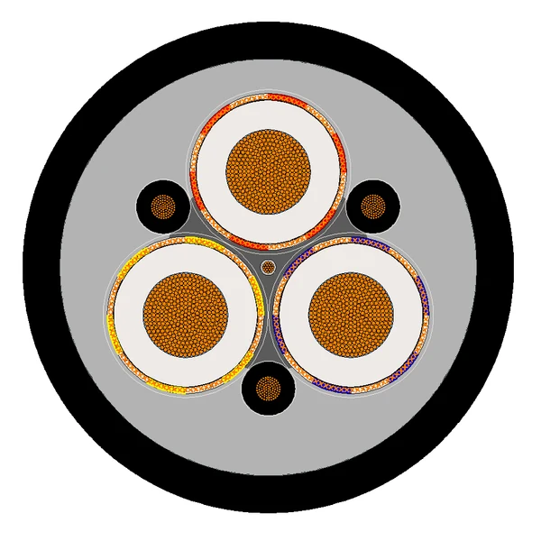
Type 240 Cross-Section Geometry: Three composite-screened phase cores plus three elastomer-covered, proofed-taped pilot cores positioned symmetrically in the outer interstices.
Technical Characteristics
Engineered to AS/NZS 1802 across four voltage ratings from 1.1/1.1 kV to 11/11 kV, Type 240 cables deliver +90 °C continuous thermal rating, −25 °C cold-installation flexibility, water immersion stability, and C1 flame retardancy.
| Parameter | AS/NZS 1802 Rated Value |
|---|---|
| Manufacturing Standard | AS/NZS 1802 (Electric cables — Reeling and trailing — For underground coal mining applications) |
| Voltage Grades & Sub-Types | Type 240.1 (1.1/1.1 kV) | Type 240.3 (3.3/3.3 kV) | Type 240.6 (6.6/6.6 kV) | Type 240.11 (11/11 kV) |
| Phase Cross-Section Range | 6–300 mm² (1.1 kV) | 16–300 mm² (3.3 kV & 6.6 kV) | 25–240 mm² (11 kV) |
| Interstitial Pilot Sizing | 3 × 1 mm² up to 3 × 35.7 mm² (scaled proportionally to phase conductor area) |
| Max. Continuous Conductor Temp. | +90 °C |
| Minimum Installation Temperature | −25 °C |
| Installation Conditions | In free air, in underground ducts, and for mobile mining equipment connections |
| Oil, Water & Flame Performance | Excellent oil/water immersion resistance, high flexibility, and C1 flame performance |
Specification & Dimensional Data (44 Standard Sizes)
Summary comparison of all four AS/NZS 1802 Type 240 voltage sub-types is presented below, followed by complete dimensional, impedance, composite screen, interstitial pilot, and mass tables.
| Sub-Type | Voltage | Stress Control | Area Range | Screen (mm²) | Pilot (mm²) | OD Range | Mass (kg/100m) |
|---|---|---|---|---|---|---|---|
| Type 240.1 | 1.1/1.1 kV | Polyester + proofed textile tapes | 6–300 mm² (13) | 8.2–49 | 1–35.7 | 31.0–94.3 mm | 150–1870 |
| Type 240.3 | 3.3/3.3 kV | Semi-conductive conductor & insul. screens | 16–300 mm² (11) | 14–63 | 3–35.7 | 47.3–97.7 mm | 340–1980 |
| Type 240.6 | 6.6/6.6 kV | Semi-conductive conductor & insul. screens | 16–300 mm² (11) | 17–71 | 3–35.7 | 58.2–109 mm | 480–2275 |
| Type 240.11 | 11/11 kV | Semi-conductive conductor & insul. screens | 25–240 mm² (9) | 24–77 | 4.5–27 | 75.9–116 mm | 815–2340 |
Type 240.1 — Rated Voltage: 1.1/1.1 kV (6 mm² to 300 mm² | 13 Sizes)
Type 240.1 (1.1/1.1 kV): Polyester conductor tape, 1.5–3.0 mm R-EP-90 EPR insulation, proofed textile tape, composite screen (8.2–49 mm²), and three interstitial pilots (1–35.7 mm²).
| Area (mm²) | Cond. Dia. (mm) | Insul. (mm) | AC Res. (Ω/km) | React. (Ω/km) | Volt Drop (mV/A·m) | Cap. (µF/km) | Screen (mm²) | Pilot (mm²) | Sheath (mm) | Cable Dia. (mm) | Mass (kg/100m) |
|---|---|---|---|---|---|---|---|---|---|---|---|
| 6 | 3.5 | 1.5 | 4.32 | 0.141 | 7.49 | 0.259 | 8.2 | 1 | 3.8 | 31.0 | 150 |
| 10 | 4.6 | 1.5 | 2.58 | 0.130 | 4.47 | 0.314 | 8.2 | 1.5 | 3.8 | 33.3 | 175 |
| 16 | 6.2 | 1.6 | 1.58 | 0.118 | 2.74 | 0.379 | 10 | 3 | 4.0 | 37.3 | 230 |
| 25 | 7.2 | 1.6 | 0.951 | 0.112 | 1.66 | 0.432 | 12 | 4.5 | 4.3 | 40.3 | 295 |
| 35 | 8.4 | 1.6 | 0.698 | 0.107 | 1.22 | 0.493 | 14 | 6 | 4.6 | 43.6 | 350 |
| 50 | 9.7 | 1.7 | 0.523 | 0.104 | 0.924 | 0.526 | 14 | 8 | 5.0 | 47.7 | 425 |
| 70 | 12.0 | 1.8 | 0.346 | 0.0981 | 0.623 | 0.599 | 16 | 12.5 | 5.4 | 54.0 | 565 |
| 95 | 13.3 | 2.0 | 0.271 | 0.0955 | 0.498 | 0.591 | 18 | 12.5 | 6.0 | 58.9 | 670 |
| 120 | 15.3 | 2.1 | 0.210 | 0.0925 | 0.397 | 0.640 | 21 | 13.75 | 6.4 | 64.6 | 815 |
| 150 | 17.2 | 2.3 | 0.166 | 0.0907 | 0.328 | 0.652 | 23 | 17 | 6.9 | 70.4 | 990 |
| 185 | 18.8 | 2.5 | 0.137 | 0.0902 | 0.284 | 0.657 | 30 | 22 | 7.4 | 76.5 | 1195 |
| 240 | 21.7 | 2.8 | 0.107 | 0.0883 | 0.240 | 0.672 | 34 | 27 | 8.2 | 85.5 | 1505 |
| 300 | 24.3 | 3.0 | 0.0850 | 0.0873 | 0.211 | 0.719 | 49 | 35.7 | 8.8 | 94.3 | 1870 |
Type 240.3 — Rated Voltage: 3.3/3.3 kV (16 mm² to 300 mm² | 11 Sizes)
Type 240.3 (3.3/3.3 kV): Semi-conductive conductor and insulation screens, 3.0 mm R-EP-90 EPR insulation, composite screen (14–63 mm²), and three interstitial pilots (3–35.7 mm²).
| Area (mm²) | Cond. Dia. (mm) | Insul. (mm) | AC Res. (Ω/km) | React. (Ω/km) | Volt Drop (mV/A·m) | Cap. (µF/km) | Screen (mm²) | Pilot (mm²) | Sheath (mm) | Cable Dia. (mm) | Mass (kg/100m) |
|---|---|---|---|---|---|---|---|---|---|---|---|
| 16 | 6.2 | 3.0 | 1.58 | 0.131 | 2.75 | 0.255 | 14 | 3 | 5.3 | 47.3 | 340 |
| 25 | 7.2 | 3.0 | 0.951 | 0.125 | 1.66 | 0.280 | 15 | 4.5 | 5.6 | 50.4 | 410 |
| 35 | 8.4 | 3.0 | 0.698 | 0.119 | 1.23 | 0.311 | 16 | 6 | 5.9 | 53.5 | 475 |
| 50 | 9.7 | 3.0 | 0.523 | 0.114 | 0.927 | 0.347 | 17 | 8 | 6.3 | 57.2 | 555 |
| 70 | 12.0 | 3.0 | 0.346 | 0.106 | 0.627 | 0.408 | 19 | 12.5 | 6.6 | 62.6 | 690 |
| 95 | 13.3 | 3.0 | 0.271 | 0.102 | 0.502 | 0.439 | 21 | 12.5 | 7.1 | 66.4 | 785 |
| 120 | 15.3 | 3.0 | 0.210 | 0.0985 | 0.402 | 0.492 | 27 | 13.75 | 7.4 | 72.0 | 955 |
| 150 | 17.2 | 3.0 | 0.166 | 0.0954 | 0.332 | 0.541 | 32 | 17 | 7.8 | 76.7 | 1130 |
| 185 | 18.8 | 3.0 | 0.137 | 0.0942 | 0.288 | 0.584 | 42 | 22 | 8.2 | 82.3 | 1330 |
| 240 | 21.7 | 3.0 | 0.106 | 0.0906 | 0.242 | 0.659 | 48 | 27 | 8.8 | 89.6 | 1615 |
| 300 | 24.3 | 3.0 | 0.0849 | 0.0890 | 0.213 | 0.727 | 63 | 35.7 | 9.4 | 97.7 | 1980 |
Type 240.6 — Rated Voltage: 6.6/6.6 kV (16 mm² to 300 mm² | 11 Sizes) — Click to Expand
Type 240.6 (6.6/6.6 kV): Semi-conductive conductor and insulation screens, 5.0 mm R-EP-90 EPR insulation, composite screen (17–71 mm²), and three interstitial pilots (3–35.7 mm²).
| Area (mm²) | Cond. Dia. (mm) | Insul. (mm) | AC Res. (Ω/km) | React. (Ω/km) | Volt Drop (mV/A·m) | Cap. (µF/km) | Screen (mm²) | Pilot (mm²) | Sheath (mm) | Cable Dia. (mm) | Mass (kg/100m) |
|---|---|---|---|---|---|---|---|---|---|---|---|
| 16 | 6.2 | 5.0 | 1.58 | 0.143 | 2.75 | 0.181 | 17 | 3 | 6.4 | 58.2 | 480 |
| 25 | 7.2 | 5.0 | 0.951 | 0.137 | 1.66 | 0.193 | 19 | 4.5 | 6.7 | 61.7 | 570 |
| 35 | 8.4 | 5.0 | 0.698 | 0.130 | 1.23 | 0.212 | 21 | 6 | 7.0 | 64.8 | 645 |
| 50 | 9.7 | 5.0 | 0.523 | 0.124 | 0.931 | 0.234 | 22 | 8 | 7.3 | 68.2 | 730 |
| 70 | 12.0 | 5.0 | 0.346 | 0.116 | 0.632 | 0.271 | 23 | 12.5 | 7.7 | 73.8 | 880 |
| 95 | 13.3 | 5.0 | 0.271 | 0.113 | 0.509 | 0.292 | 30 | 12.5 | 8.1 | 78.0 | 1020 |
| 120 | 15.3 | 5.0 | 0.210 | 0.108 | 0.409 | 0.325 | 32 | 13.75 | 8.5 | 83.2 | 1180 |
| 150 | 17.2 | 5.0 | 0.166 | 0.105 | 0.340 | 0.354 | 46 | 17 | 8.9 | 89.2 | 1410 |
| 185 | 18.8 | 5.0 | 0.136 | 0.102 | 0.294 | 0.381 | 48 | 22 | 9.3 | 93.6 | 1585 |
| 240 | 21.7 | 5.0 | 0.106 | 0.0981 | 0.250 | 0.426 | 53 | 27 | 9.9 | 101 | 1885 |
| 300 | 24.3 | 5.0 | 0.0845 | 0.0959 | 0.221 | 0.467 | 71 | 35.7 | 10.4 | 109 | 2275 |
Type 240.11 — Rated Voltage: 11/11 kV (25 mm² to 240 mm² | 9 Sizes) — Click to Expand
Type 240.11 (11/11 kV): Semi-conductive conductor and insulation screens, 7.6 mm R-EP-90 EPR insulation, composite screen (24–77 mm²), and three interstitial pilots (4.5–27 mm²).
| Area (mm²) | Cond. Dia. (mm) | Insul. (mm) | AC Res. (Ω/km) | React. (Ω/km) | Volt Drop (mV/A·m) | Cap. (µF/km) | Screen (mm²) | Pilot (mm²) | Sheath (mm) | Cable Dia. (mm) | Mass (kg/100m) |
|---|---|---|---|---|---|---|---|---|---|---|---|
| 25 | 7.2 | 7.6 | 0.951 | 0.150 | 1.67 | 0.150 | 24 | 4.5 | 8.1 | 75.9 | 815 |
| 35 | 8.4 | 7.6 | 0.698 | 0.143 | 1.23 | 0.163 | 30 | 6 | 8.4 | 79.6 | 930 |
| 50 | 9.7 | 7.6 | 0.523 | 0.136 | 0.936 | 0.178 | 32 | 8 | 8.7 | 83.0 | 1025 |
| 70 | 12.0 | 7.6 | 0.346 | 0.127 | 0.638 | 0.204 | 35 | 12.5 | 9.1 | 88.7 | 1210 |
| 95 | 13.3 | 7.6 | 0.271 | 0.124 | 0.516 | 0.219 | 48 | 12.5 | 9.6 | 93.8 | 1385 |
| 120 | 15.3 | 7.6 | 0.210 | 0.119 | 0.418 | 0.241 | 53 | 13.75 | 9.9 | 98.7 | 1565 |
| 150 | 17.2 | 7.6 | 0.165 | 0.114 | 0.347 | 0.261 | 56 | 17 | 10.3 | 103 | 1765 |
| 185 | 18.8 | 7.6 | 0.136 | 0.111 | 0.304 | 0.279 | 56 | 22 | 10.7 | 108 | 1945 |
| 240 | 21.7 | 7.6 | 0.106 | 0.107 | 0.261 | 0.309 | 77 | 27 | 11.3 | 116 | 2340 |
Selection, Multi-Pilot Wiring & AS/NZS 1802 Model Comparison
Choosing between Type 240, Type 209, and Type 241 hinges on feeder route distance, earth-continuity pilot relay impedance limits, and whether metallic composite screening or semiconductive elastomer screening is preferred.
| Engineering Scenario | Recommended AS/NZS 1802 Practice |
|---|---|
| Long Feeder Runs (Pilot Loop Limit) | Specify Type 240. Connecting its three large interstitial pilots (up to 35.7 mm² each) in parallel鈥攐r dedicating two to control/interlock and one to earth continuity鈥攅liminates pilot resistance bottlenecks over multi-hundred-meter panel advances. |
| Standard Single-Pilot Feeder Runs | Where a single central extensible pilot satisfies gate-end relay loop resistance, compare AS/NZS 1802 Type 209 for slightly lighter cable mass per 100 m at identical outer diameters. |
| High-Flex Monorail & Trailing Duty | For continuous miners and monorail DCB loops where metallic screen wire breakage from repeated tight bending is a concern, evaluate semiconductive-screened Type 241 or narrow-loop Type 241SF (Superflex). |
Frequently Asked Questions (FAQ)
Common engineering questions regarding AS/NZS 1802 Type 240 pilot sizing, voltage sub-types, and reinforced sheath options.
What is the exact structural difference between AS/NZS 1802 Type 240 and Type 209?
Type 209 contains one small extensible central pilot core, whereas Type 240 places three separate elastomer-covered and proofed-taped pilot conductors (1 mm² to 35.7 mm²) in the three outer interstitial cavities. In addition, Type 240.1 extends down to a 6 mm² phase size at 1.1/1.1 kV.
When are semi-conductive screens applied inside Type 240 cables?
At 1.1/1.1 kV (Type 240.1), polyester conductor tape and proofed textile insulation tape are used beneath the composite braid. At 3.3/3.3 kV (Type 240.3), 6.6/6.6 kV (Type 240.6), and 11/11 kV (Type 240.11), semi-conductive conductor and insulation screens are applied to prevent partial discharge under medium-voltage stress.
Is a reinforced HD-85-PCP outer sheath available for severe drag or shaft duty?
Yes. Alongside the standard heavy-duty HD-85-PCP sheath (3.8–11.3 mm nominal wall), TEBAOFLEX manufactures Type 240 with an integral open-weave reinforced HD-85-PCP sheath or custom colour striping upon project request.
Need a Custom Type 240 Long-Run Mining Feeder Quotation?
Share your required voltage grade (1.1 kV to 11 kV), conductor cross-section (6–300 mm²), feeder route length, and drum schedule with TEBAOFLEX engineering sales.
Explore All Mining & Tunneling Cables