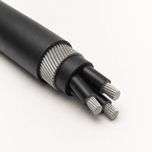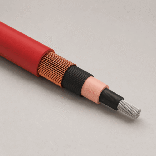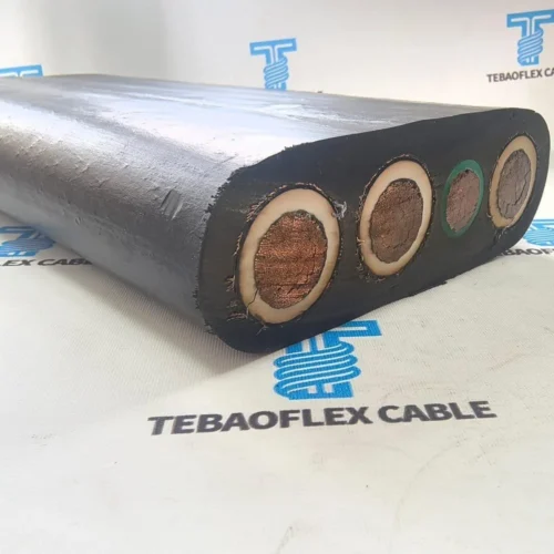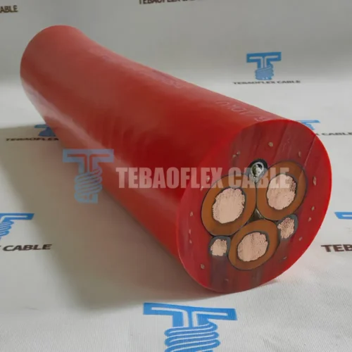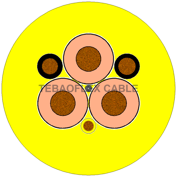
Portable medium-voltage mining trailing cable
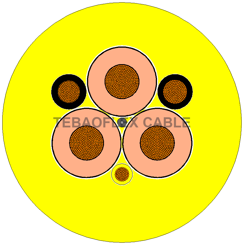
A yellow polyurethane-jacketed portable trailing cable with three power, two ground and one ground-check conductor. The three voltage grades are kept in one family page with their individual insulation thickness and dimensional data.
Where it is used
Portable power to shovels, draglines, drills, dredges and other heavy mine equipment using compatible cable reels and ground-check circuits.
Cable construction
| Component | Specification |
|---|---|
| Power conductor | Fine-stranded Class 5 tinned copper |
| Insulation | Thermosetting EPR with semi-conductive conductor and insulation screens |
| Ground / ground check | Two tinned-copper ground conductors and one insulated tinned-copper ground-check conductor |
| Outer jacket | Yellow oil-resistant thermoplastic polyurethane (TPU) |
Operating and selection data
| Parameter | Documented value / selection note |
|---|---|
| Rated voltage | 6/10, 8.7/15 and 14/25 kV |
| Maximum conductor temperature | +90 °C |
| Cold flexibility | −30 °C stated in the datasheet |
| Minimum bending radius | 4 × OD fixed; 7.5 × OD free bending on drum |
Dimensions by voltage and configuration
Nominal values from the company datasheet. Dimensions and weights may vary within manufacturing tolerances; electrical ratings depend on the stated installation conditions.
| Voltage (kV) | Configuration (mm²) | Power stranding | Ground / GC stranding | Insulation (mm) | Jacket (mm) | OD (mm) | R20 (Ω/km) | Current (A) | Weight (kg/km) |
|---|---|---|---|---|---|---|---|---|---|
| 6/10 | 3×70+2×35+1×35 | 514×0.4 | 254×0.4/254×0.4 | 2.9 | 5.5 | 53.2 | 0.277 | 250 | 5050 |
| 6/10 | 3×95+2×35+1×35 | 684×0.4 | 254×0.4/254×0.4 | 2.9 | 5.5 | 61.0 | 0.210 | 301 | 6401 |
| 6/10 | 3×120+2×50+1×35 | 870×0.4 | 364×0.4/254×0.4 | 2.9 | 5.5 | 64.7 | 0.164 | 352 | 7067 |
| 6/10 | 3×185+2×70+1×35 | 1325×0.4 | 514×0.4/254×0.4 | 2.9 | 5.5 | 74.0 | 0.108 | 461 | 10300 |
| 8.7/15 | 3×70+2×35+1×35 | 514×0.4 | 254×0.4/254×0.4 | 3.7 | 5.5 | 61.0 | 0.277 | 265 | 5300 |
| 8.7/15 | 3×95+2×35+1×35 | 684×0.4 | 254×0.4/254×0.4 | 3.7 | 5.5 | 66.0 | 0.210 | 319 | 6300 |
| 8.7/15 | 3×120+2×50+1×35 | 870×0.4 | 364×0.4/254×0.4 | 3.7 | 5.5 | 70.0 | 0.164 | 371 | 7600 |
| 8.7/15 | 3×185+2×70+1×35 | 1325×0.4 | 514×0.4/254×0.4 | 3.7 | 5.5 | 77.5 | 0.108 | 488 | 11300 |
| 14/25 | 3×70+2×35+1×35 | 514×0.4 | 254×0.4/254×0.4 | 5.5 | 5.5 | 67.4 | 0.277 | 265 | 7200 |
| 14/25 | 3×95+2×35+1×35 | 684×0.4 | 254×0.4/254×0.4 | 5.5 | 5.5 | 73.0 | 0.210 | 319 | 8200 |
| 14/25 | 3×120+2×50+1×35 | 870×0.4 | 364×0.4/254×0.4 | 5.5 | 5.5 | 76.0 | 0.164 | 371 | 8600 |
| 14/25 | 3×185+2×70+1×35 | 1325×0.4 | 514×0.4/254×0.4 | 5.5 | 5.5 | 84.0 | 0.108 | 488 | 13200 |
Installation limits
Confirm ground-check circuit compatibility, reel bending, termination and project-specific approval requirements; an approval number in the source PDF is not claimed for every configuration here.
Technical datasheets
Standards named in the datasheets are design or test references; request the applicable certificate and test evidence for the exact product configuration.
Request a configuration review
Send the voltage, conductor size, core arrangement, moving or fixed duty, bend radius, environment, required length and quantity to TEBAOFLEX. We will confirm the construction and commercial details for the project.