Application & Operating Conditions
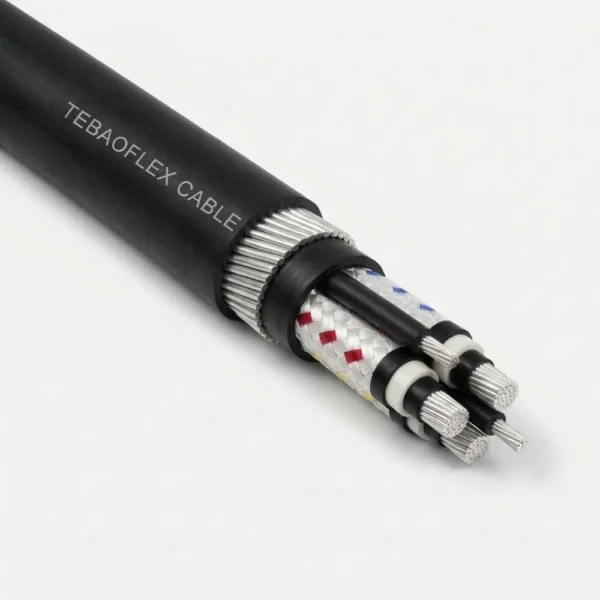
AS/NZS 1802 Type 260 is a pliable galvanised steel wire armoured (PSWA) rubber mining feeder cable (1.1 kV to 11 kV, 6–300 mm²) designed for semi-mobile underground substations, gate-end distribution control boxes (DCBs), pump stations, and roadway feeders exposed to rockfall impact, rib convergence, and mobile plant crush hazards.
Semi-Mobile Substations & DCB Feeders
Pliable 7-wire galvanised steel armour strands (7/0.45, 7/0.90, and 7/1.25 mm) enable repeated relocation as longwall panels retreat without the stiffness of solid-wire SWA cables.
High-Impact Underground Roadways
Dual elastomer sheathing (2.0–4.5 mm PCP inner bedding + 3.8–10.7 mm heavy-duty PCP outer jacket) combined with helical steel wire armour resists roof spall, floor heave, and abrasion.
Composite Earth Fault & Pilot Protection
Each power core incorporates an individual tinned-copper/polyester composite screen (7.2–71.5 mm² per core) paired with an EPR-insulated interstitial pilot for earth-continuity tripping.
Need Unarmoured Flexible Feeder or Trailing Cable? Where armour is not required and lighter handling or continuous reeling is prioritized, compare Type 240 (3-Pilot Unarmoured Feeder) or Type 209 (Composite Screened Trailing Cable).
Cable Construction (AS/NZS 1802 Type 260)
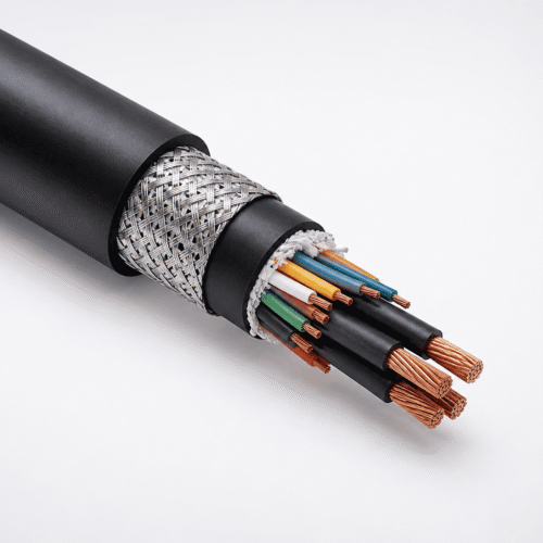
Type 260 integrates seven concentric engineering layers from flexible tinned copper conductors and composite phase screens through PCP inner bedding, pliable stranded galvanised steel armour, and heavy-duty PCP outer sheathing.
| Layer / Component | Material & AS/NZS 1802 Specification |
|---|---|
| 1. Phase Conductors | Flexible stranded tinned annealed copper, three phase cores (84/0.30 on 6 mm² up to 854/0.67 on 300 mm²) |
| 2. Conductor Screen | Extruded semi-conductive compound applied on cables rated 3.3 kV, 6.6 kV, and 11 kV |
| 3. Insulation & Elastomer Screen | R-EP-90 EPR thermosetting insulation + extruded semi-conductive elastomer insulation screen |
| 4. Composite Core Screen | Tinned annealed copper wire braid interwoven with polyester yarn over each phase core (7.2 mm² to 71.5 mm² effective copper area) |
| 5. Cradle & Interstitial Pilot | Semiconductive PCP cradle separator + one EPR-covered flexible tinned copper pilot laid in the outer interstice |
| 6. Inner Sheath & Pliable Armour | Extruded PCP inner bedding sheath (2.0–4.5 mm) armored with helical pliable stranded galvanised steel wires (7/0.45, 7/0.90, or 7/1.25 mm) |
| 7. Heavy-Duty Outer Sheath | Black heavy-duty PCP outer sheath (3.8–10.7 mm nominal radial thickness; CPE/CSP compounds available on request) |
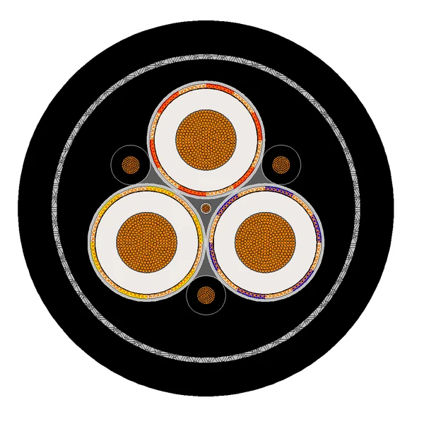
Type 260 Cross-Section Geometry: Three composite-screened EPR phase cores and one interstitial EPR-covered pilot enclosed in a PCP inner sheath, encircled by 7-wire pliable galvanised steel armour bundles and a heavy PCP outer sheath.
Technical Characteristics
Engineered to AS/NZS 1802 across four voltage classes (1.1 kV to 11 kV), Type 260 provides armoured mechanical crush protection while preserving pliable coiling and relocation capability underground.
| Parameter | AS/NZS 1802 Rated Value |
|---|---|
| Manufacturing Standard | AS/NZS 1802 (Electric cables — Reeling and trailing — For underground coal mining applications) |
| Voltage Grades & Sub-Types | Type 260.1 (1.1/1.1 kV) | Type 260.3 (3.3/3.3 kV) | Type 260.6 (6.6/6.6 kV) | Type 260.11 (11/11 kV) |
| Conductor Cross-Section Range | 6–300 mm² (1.1 kV) | 16–300 mm² (3.3 kV & 6.6 kV) | 25–185 mm² (11 kV) |
| Pliable Armour Stranding | 7-wire stranded galvanised steel (7/0.45 mm on small LV; 7/0.90 mm mid-range; 7/1.25 mm large/MV) |
| Max. Continuous Conductor Temp. | +90 °C |
| Minimum Installation Temperature | −25 °C |
| Recommended Service Duty | Semi-mobile substation feeders, gate-end DCB distribution, and armored roadway power supply |
| Outer Sheath & Flame Performance | Black heavy-duty PCP standard (coloured / CPE / CSP on request) | C1 vertical flame retardant |
Specification & Armour Data (43 Standard Sizes)
Complete dimensional, copper screen area, pliable steel armour stranding, dual sheath thickness, and mass tables for AS/NZS 1802 Type 260.1 (1.1 kV), Type 260.3 (3.3 kV), Type 260.6 (6.6 kV), and Type 260.11 (11 kV).
| Sub-Type | Voltage | Size Range | Armour Strands | Inner / Outer PCP | OD Range | Mass (kg/100m) |
|---|---|---|---|---|---|---|
| Type 260.1 | 1.1/1.1 kV | 6–300 mm² (13) | 7/0.45 – 7/1.25 | 2.0–4.5 / 3.8–8.8 mm | 36.9–112.1 mm | 230–2590 |
| Type 260.3 | 3.3/3.3 kV | 16–300 mm² (11) | 7/0.90 – 7/1.25 | 2.5–4.5 / 5.3–9.4 mm | 56.9–115.4 mm | 566–2710 |
| Type 260.6 | 6.6/6.6 kV | 16–300 mm² (11) | 7/0.90 – 7/1.25 | 3.5–4.5 / 6.4–10.4 mm | 70.1–126.3 mm | 796–3060 |
| Type 260.11 | 11/11 kV | 25–185 mm² (8) | 7/1.25 | 4.5 / 8.1–10.7 mm | 92.7–125.9 mm | 1380–2750 |
Type 260.1 — Rated Voltage: 1.1/1.1 kV (6 mm² to 300 mm² | 13 Sizes)
| Area (mm²) | Cond. Strand | Insul. (mm) | Screen Strand | Screen (mm²) | Pilot Strand | Pilot Cover (mm) | Armour (No./mm) | Inner Sheath (mm) | Outer Sheath (mm) | Cable Dia. (mm) | Mass (kg/100m) |
|---|---|---|---|---|---|---|---|---|---|---|---|
| 3 × 6 | 84 / 0.30 | 1.5 | 7 / 0.25 | 7.2 | 18 / 0.30 | 1.0 | 7 / 0.45 | 2.0 | 3.8 | 36.9 | 230 |
| 3 × 10 | 77 / 0.40 | 1.5 | 7 / 0.25 | 8.6 | 27 / 0.30 | 1.0 | 7 / 0.45 | 2.0 | 3.8 | 39.5 | 265 |
| 3 × 16 | 126 / 0.40 | 1.6 | 7 / 0.25 | 9.6 | 42 / 0.30 | 1.0 | 7 / 0.90 | 2.5 | 4.0 | 46.5 | 410 |
| 3 × 25 | 209 / 0.40 | 1.6 | 7 / 0.25 | 11.3 | 66 / 0.30 | 1.2 | 7 / 0.90 | 2.5 | 4.3 | 50.4 | 495 |
| 3 × 35 | 285 / 0.40 | 1.6 | 7 / 0.25 | 12.4 | 90 / 0.30 | 1.2 | 7 / 0.90 | 2.5 | 4.6 | 53.8 | 576 |
| 3 × 50 | 380 / 0.40 | 1.7 | 7 / 0.25 | 14.1 | 120 / 0.30 | 1.2 | 7 / 0.90 | 2.5 | 5.0 | 58.4 | 679 |
| 3 × 70 | 203 / 0.67 | 1.8 | 7 / 0.25 | 16.5 | 39 / 0.67 | 1.2 | 7 / 0.90 | 2.5 | 5.4 | 64.6 | 837 |
| 3 × 95 | 259 / 0.67 | 2.0 | 7 / 0.25 | 18.2 | 39 / 0.67 | 1.2 | 7 / 0.90 | 3.5 | 6.0 | 71.4 | 1003 |
| 3 × 120 | 336 / 0.67 | 2.1 | 7 / 0.25 | 20.3 | 42 / 0.67 | 1.4 | 7 / 0.90 | 3.5 | 6.4 | 77.2 | 1176 |
| 3 × 150 | 427 / 0.67 | 2.3 | 7 / 0.25 | 22.3 | 54 / 0.67 | 1.4 | 7 / 0.90 | 3.5 | 6.9 | 83.0 | 1372 |
| 3 × 185 | 518 / 0.67 | 2.5 | 7 / 0.30 | 30.2 | 63 / 0.67 | 1.4 | 7 / 0.90 | 3.5 | 7.4 | 90.0 | 1610 |
| 3 × 240 | 672 / 0.67 | 2.8 | 7 / 0.30 | 33.6 | 77 / 0.67 | 1.6 | 7 / 1.25 | 4.5 | 8.2 | 103.0 | 2150 |
| 3 × 300 | 854 / 0.67 | 3.0 | 7 / 0.40 | 50.1 | 98 / 0.67 | 1.6 | 7 / 1.25 | 4.5 | 8.8 | 112.1 | 2590 |
Type 260.3 — Rated Voltage: 3.3/3.3 kV (16 mm² to 300 mm² | 11 Sizes)
| Area (mm²) | Cond. Strand | Insul. (mm) | Screen Strand | Screen (mm²) | Pilot Strand | Pilot Cover (mm) | Armour (No./mm) | Inner Sheath (mm) | Outer Sheath (mm) | Cable Dia. (mm) | Mass (kg/100m) |
|---|---|---|---|---|---|---|---|---|---|---|---|
| 3 × 16 | 126 / 0.40 | 3.0 | 7 / 0.25 | 13.1 | 42 / 0.30 | 1.4 | 7 / 0.90 | 2.5 | 5.3 | 56.9 | 566 |
| 3 × 25 | 209 / 0.40 | 3.0 | 7 / 0.25 | 14.8 | 66 / 0.30 | 1.4 | 7 / 0.90 | 2.5 | 5.6 | 60.8 | 661 |
| 3 × 35 | 285 / 0.40 | 3.0 | 7 / 0.25 | 15.8 | 90 / 0.30 | 1.4 | 7 / 0.90 | 3.5 | 5.9 | 66.3 | 779 |
| 3 × 50 | 380 / 0.40 | 3.0 | 7 / 0.25 | 17.2 | 120 / 0.30 | 1.4 | 7 / 0.90 | 3.5 | 6.3 | 70.4 | 886 |
| 3 × 70 | 203 / 0.67 | 3.0 | 7 / 0.25 | 18.6 | 39 / 0.67 | 1.4 | 7 / 0.90 | 3.5 | 6.6 | 75.3 | 1044 |
| 3 × 95 | 259 / 0.67 | 3.0 | 7 / 0.25 | 20.3 | 39 / 0.67 | 1.4 | 7 / 0.90 | 3.5 | 7.1 | 78.9 | 1156 |
| 3 × 120 | 336 / 0.67 | 3.0 | 7 / 0.30 | 27.2 | 42 / 0.67 | 1.6 | 7 / 0.90 | 3.5 | 7.4 | 84.7 | 1350 |
| 3 × 150 | 427 / 0.67 | 3.0 | 7 / 0.40 | 39.6 | 54 / 0.67 | 1.6 | 7 / 1.25 | 4.5 | 7.8 | 95.0 | 1779 |
| 3 × 185 | 518 / 0.67 | 3.0 | 7 / 0.40 | 42.2 | 63 / 0.67 | 1.8 | 7 / 1.25 | 4.5 | 8.2 | 100.4 | 1990 |
| 3 × 240 | 672 / 0.67 | 3.0 | 7 / 0.40 | 46.6 | 77 / 0.67 | 1.8 | 7 / 1.25 | 4.5 | 8.8 | 107.3 | 2300 |
| 3 × 300 | 854 / 0.67 | 3.0 | 7 / 0.50 | 63.2 | 98 / 0.67 | 1.8 | 7 / 1.25 | 4.5 | 9.4 | 115.4 | 2710 |
Type 260.6 — Rated Voltage: 6.6/6.6 kV (16 mm² to 300 mm² | 11 Sizes)
| Area (mm²) | Cond. Strand | Insul. (mm) | Screen Strand | Screen (mm²) | Pilot Strand | Pilot Cover (mm) | Armour (No./mm) | Inner Sheath (mm) | Outer Sheath (mm) | Cable Dia. (mm) | Mass (kg/100m) |
|---|---|---|---|---|---|---|---|---|---|---|---|
| 3 × 16 | 126 / 0.40 | 5.0 | 7 / 0.25 | 17.2 | 42 / 0.30 | 1.4 | 7 / 0.90 | 3.5 | 6.4 | 70.1 | 796 |
| 3 × 25 | 209 / 0.40 | 5.0 | 7 / 0.25 | 18.6 | 66 / 0.30 | 1.4 | 7 / 0.90 | 3.5 | 6.7 | 74.0 | 897 |
| 3 × 35 | 285 / 0.40 | 5.0 | 7 / 0.25 | 18.6 | 90 / 0.30 | 1.6 | 7 / 0.90 | 3.5 | 7.0 | 77.4 | 990 |
| 3 × 50 | 380 / 0.40 | 5.0 | 7 / 0.25 | 21.3 | 120 / 0.30 | 1.6 | 7 / 0.90 | 3.5 | 7.3 | 81.2 | 1102 |
| 3 × 70 | 203 / 0.67 | 5.0 | 7 / 0.25 | 23.4 | 39 / 0.67 | 1.6 | 7 / 1.25 | 4.5 | 7.7 | 90.7 | 1456 |
| 3 × 95 | 259 / 0.67 | 5.0 | 7 / 0.30 | 29.2 | 39 / 0.67 | 1.6 | 7 / 1.25 | 4.5 | 8.1 | 94.8 | 1610 |
| 3 × 120 | 336 / 0.67 | 5.0 | 7 / 0.30 | 31.7 | 42 / 0.67 | 1.8 | 7 / 1.25 | 4.5 | 8.5 | 100.2 | 1807 |
| 3 × 150 | 427 / 0.67 | 5.0 | 7 / 0.40 | 45.7 | 54 / 0.67 | 1.8 | 7 / 1.25 | 4.5 | 8.9 | 106.2 | 2080 |
| 3 × 185 | 518 / 0.67 | 5.0 | 7 / 0.40 | 48.4 | 63 / 0.67 | 1.8 | 7 / 1.25 | 4.5 | 9.3 | 111.5 | 2300 |
| 3 × 240 | 672 / 0.67 | 5.0 | 7 / 0.40 | 52.8 | 77 / 0.67 | 1.8 | 7 / 1.25 | 4.5 | 9.9 | 118.4 | 2630 |
| 3 × 300 | 854 / 0.67 | 5.0 | 7 / 0.50 | 71.5 | 98 / 0.67 | 1.8 | 7 / 1.25 | 4.5 | 10.4 | 126.3 | 3060 |
Type 260.11 — Rated Voltage: 11/11 kV (25 mm² to 185 mm² | 8 Sizes)
| Area (mm²) | Cond. Strand | Insul. (mm) | Screen Strand | Screen (mm²) | Pilot Strand | Pilot Cover (mm) | Armour (No./mm) | Inner Sheath (mm) | Outer Sheath (mm) | Cable Dia. (mm) | Mass (kg/100m) |
|---|---|---|---|---|---|---|---|---|---|---|---|
| 3 × 25 | 209 / 0.40 | 7.6 | 7 / 0.25 | 23.7 | 66 / 0.30 | 2.0 | 7 / 1.25 | 4.5 | 8.1 | 92.7 | 1380 |
| 3 × 35 | 285 / 0.40 | 7.6 | 7 / 0.30 | 30.2 | 90 / 0.30 | 2.0 | 7 / 1.25 | 4.5 | 8.4 | 96.7 | 1528 |
| 3 × 50 | 380 / 0.40 | 7.6 | 7 / 0.30 | 31.7 | 120 / 0.30 | 2.0 | 7 / 1.25 | 4.5 | 8.7 | 100.6 | 1664 |
| 3 × 70 | 203 / 0.67 | 7.6 | 7 / 0.30 | 34.1 | 39 / 0.67 | 2.0 | 7 / 1.25 | 4.5 | 9.1 | 105.8 | 1867 |
| 3 × 95 | 259 / 0.67 | 7.6 | 7 / 0.40 | 47.5 | 39 / 0.67 | 2.0 | 7 / 1.25 | 4.5 | 9.6 | 110.7 | 2080 |
| 3 × 120 | 336 / 0.67 | 7.6 | 7 / 0.40 | 51.0 | 42 / 0.67 | 2.2 | 7 / 1.25 | 4.5 | 9.9 | 115.8 | 2290 |
| 3 × 150 | 427 / 0.67 | 7.6 | 7 / 0.40 | 53.7 | 54 / 0.67 | 2.2 | 7 / 1.25 | 4.5 | 10.3 | 120.5 | 2510 |
| 3 × 185 | 518 / 0.67 | 7.6 | 7 / 0.40 | 57.2 | 63 / 0.67 | 2.2 | 7 / 1.25 | 4.5 | 10.7 | 125.9 | 2750 |
Selection: Type 260 Armoured vs. Type 240 / Type 209 Unarmoured
Choosing between pliable steel wire armoured Type 260 and unarmoured AS/NZS 1802 feeders depends on roadway rockfall/crush exposure, relocation frequency, and reeling requirements.
| Cable Model | Mechanical Protection, Pilot Layout & Recommended Duty |
|---|---|
| Type 260 (This Product) | Pliable 7-wire galvanised steel armour + PCP inner & outer sheaths + 1 interstitial pilot + composite copper screens. Best for semi-mobile roadway feeders, DCBs, and substations subject to crush or rockfall impact (NOT for dynamic drum reeling). |
| Type 240 (Unarmoured Feeder) | Type 240 omits steel armour in favor of lighter weight and three interstitial pilots, ideal for suspended rib hangers or protected gate-road DCB interconnects. |
| Type 209 / Type 241 (Trailing) | For mobile mining machines requiring continuous trailing or reeling behind the DCB, specify unarmoured Type 209 or semiconductive-screened Type 241. |
Frequently Asked Questions (FAQ)
Engineering answers regarding Type 260 pliable steel wire armour, earth fault capacity, and underground coupler terminations.
How does pliable wire armour (PSWA) on Type 260 differ from standard solid SWA?
Instead of rigid single steel wires, Type 260 uses 7-wire stranded galvanised steel armour bundles (7/0.45, 7/0.90, or 7/1.25 mm) cushioned over an extruded PCP inner sheath. This allows underground crews to coil, drag, and re-route substation feeders as panels advance without kinking or bird-caging the armour.
Does Type 260 rely on the steel armour alone for earth return?
No. Every phase core is individually screened with a high-conductivity tinned copper / polyester composite braid (7.2 mm² to 71.5 mm² per core) in addition to the pliable galvanised steel armour and interstitial EPR-covered pilot conductor, ensuring low-impedance earth fault clearance across long roadway runs.
Is Type 260 compatible with flameproof bolted couplers and armour glands?
Yes. Nominal core insulation diameters, inner bedding walls, and overall cable diameters are controlled to AS/NZS 1802 tolerances for Australian/NZ mining armour clamping glands and 1.1 kV–11 kV flameproof bolted couplers.
Request a Quote for AS/NZS 1802 Type 260 Armoured Mining Cables
Specify your voltage rating (1.1 kV to 11 kV), conductor size (6–300 mm²), sheath compound, and drum length for factory pricing and routine test documentation.
Explore All Mining & Tunneling Cables