Application & Operating Conditions
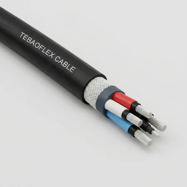
AS/NZS 1802 Type 241SF (also designated Type 241 Superflex) is a maximum-flexibility semiconductive screened mining cable (1.1/1.1 kV to 11/11 kV, 70–300 mm²) engineered specifically to achieve a smaller natural bending radius in arduous underground coal and metalliferous roadways. Its extra-supple core lay forms narrower overhead monorail cable loops that clear passing haulage vehicles and minimize snagging hazards.
Narrow-Loop Longwall Monorails
Specially developed for overhead monorail carrier loops feeding distribution control boxes (DCBs) and longwall gate roads where large, stiff 70–300 mm² cables bow outward into mobile equipment travel lanes.
Continuous Miners & Tight Handling
Multi-bunched 0.50 mm rope-lay tinned copper phase conductors (up to 1,221 strands per core) drastically lower bending stiffness during manual figure-eight coiling and continuous miner trailing maneuvers.
Semiconductive PCP Core Cushioning
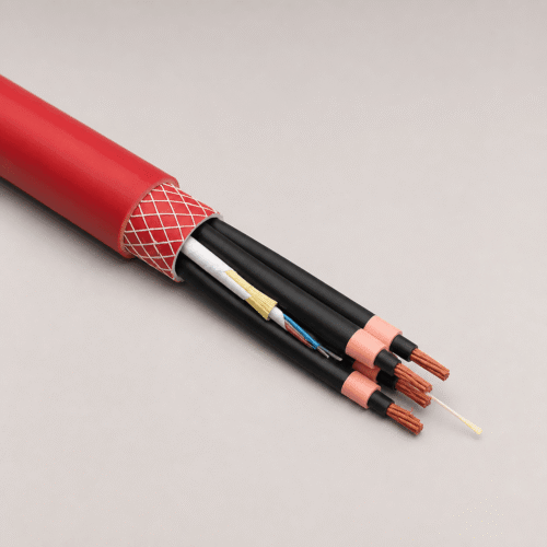
A semiconductive PCP cradle separator and overall core filling cushion internal shear forces under repeated tight flexing, backed by open-weave braid reinforcement and a C1 flame-retardant HD-85-PCP jacket.
Size Range Engineering Note: Because smaller 6–50 mm² cables already bend easily in standard construction, Type 241SF (Superflex) is standardized strictly for heavy 70 mm² to 300 mm² power cross-sections. For 6–50 mm² circuits or general feeder runs, see standard AS/NZS 1802 Type 241.
Cable Construction (AS/NZS 1802 Type 241SF / Superflex)
Type 241SF enhances standard Type 241 geometry with ultra-fine rope-lay tinned copper stranding, a semiconductive PCP cradle separator, semiconductive PCP overall core filling/covering, and open-weave reinforced HD-85-PCP (or optional CPE/CSP) sheathing.
| Layer / Component | Material & Superflex Specification |
|---|---|
| 1. Superflex Conductors | Extra-flexible rope-lay stranded tinned annealed copper, three phase cores (e.g., 361/0.50 mm on 70 mm² up to 1221/0.50 mm on 240 mm²) |
| 2. Conductor Screen | Polyester separator where necessary for 1.1/1.1 kV; extruded semi-conductive compound for 3.3/3.3 kV, 6.6/6.6 kV, and 11/11 kV |
| 3. Insulation & Core ID | Ethylene-propylene rubber compound (R-EP-90 EPR) with durably printed core numbers / phase colours |
| 4. Insulation Screen | Flexible semi-conductive elastomer screen applied over each insulated phase core |
| 5. Cradle & Core Screen | Semiconductive PCP cradle separator plus semiconductive PCP overall core filling and covering stabilizing core geometry in narrow loops |
| 6. Earth & Pilot Cores | Three interstitial earth conductors (0.40 mm tinned Cu strands with 1.0–1.4 mm semiconductive PCP cover) + one central extensible pilot (40/0.20 mm tinned Cu with 0.8 mm EPR cover) |
| 7. Reinforcement & Sheath | Open-weave braid reinforcement under heavy-duty HD-85-PCP elastomer sheath (heavy-duty CPE/CSP sheath available on request) |
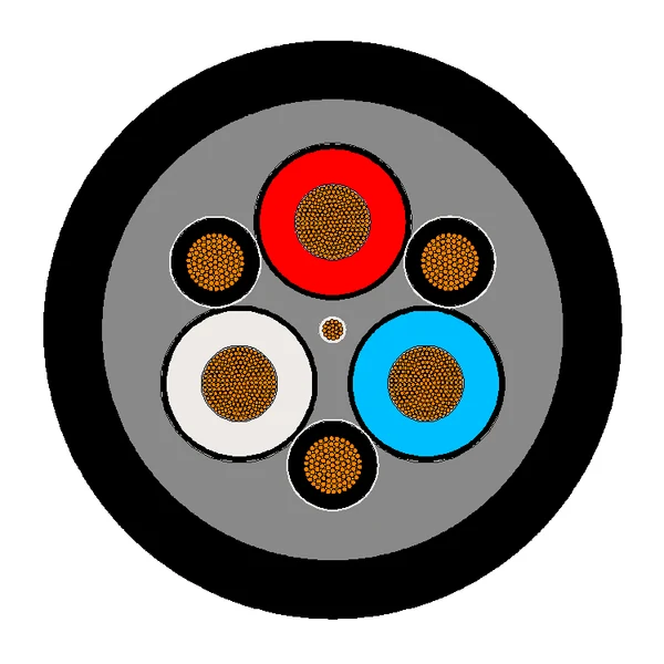
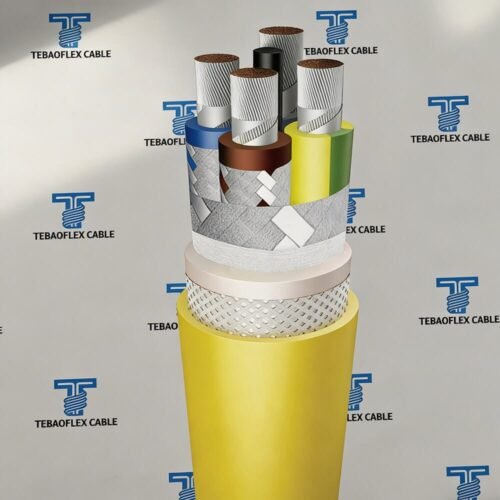
Type 241SF Cross-Section Geometry: Grey semiconductive PCP cradle filling and overall covering surround the three extra-flexible EPR phase cores, three interstitial earths, and central extensible pilot.
Technical Characteristics
Built to AS/NZS 1802 across 1.1/1.1 kV to 11/11 kV, Type 241SF combines a reduced natural bending loop profile with full +90 °C thermal capacity, water/oil immersion durability, and C1 flame performance.
| Parameter | AS/NZS 1802 Rated Value |
|---|---|
| Manufacturing Standard | AS/NZS 1802 (Electric cables — Reeling and trailing — For underground coal mining applications) |
| Voltage Grades & Sub-Types | Type 241.1 SF (1.1/1.1 kV) | Type 241.3 SF (3.3/3.3 kV) | Type 241.6 SF (6.6/6.6 kV) | Type 241.11 SF (11/11 kV) |
| Phase Cross-Section Range | 70–300 mm² (1.1 kV, 3.3 kV & 6.6 kV) | 70–240 mm² (11 kV) |
| Mechanical Flexibility Grade | Superflex (SF) extra-flexible rope-lay construction for smaller natural monorail bending radius |
| Max. Continuous Conductor Temp. | +90 °C |
| Minimum Installation Temperature | −25 °C |
| Installation Duty | Overhead monorail cable loops, flexible trailing and reeling service, free air, and underground ducts |
| Flame Performance & Sheath Options | C1 flame retardant; standard HD-85-PCP sheath (CPE/CSP elastomer sheath available upon request) |
Specification, Electrical & Superflex Stranding Data
Complete nominal dimensional and electrical specifications for all 27 Type 241SF sizes (1.1 kV to 11 kV) are detailed below, followed by the physical conductor, earth, and pilot wire stranding schedule.
| Sub-Type | Voltage | Area Range | EPR Insul. | Earth Core (mm²) | Sheath Wall | OD Range | Mass (kg/100m) |
|---|---|---|---|---|---|---|---|
| Type 241.1 SF | 1.1/1.1 kV | 70–300 mm² (7) | 1.8–3.0 mm | 12.5–35.7 | 5.3–8.7 mm | 52.7–91.2 mm | 525–1715 |
| Type 241.3 SF | 3.3/3.3 kV | 70–300 mm² (7) | 3.0 mm | 12.5–50 | 6.4–9.1 mm | 60.9–92.7 mm | 635–1775 |
| Type 241.6 SF | 6.6/6.6 kV | 70–300 mm² (7) | 5.0 mm | 12.5–50 | 7.4–10.2 mm | 72.0–104 mm | 820–2040 |
| Type 241.11 SF | 11/11 kV | 70–240 mm² (6) | 7.6 mm | 12.5–39.5 | 8.9–11.0 mm | 86.4–111 mm | 1090–2080 |
Type 241.1 SF — Rated Voltage: 1.1/1.1 kV (70 mm² to 300 mm² | 7 Sizes)
Type 241.1 SF (1.1/1.1 kV): Superflex tinned copper stranding, 1.8–3.0 mm R-EP-90 EPR insulation, semiconductive PCP cradle, three interstitial earths (12.5–35.7 mm²), and reinforced HD-85-PCP sheath.
| Area (mm²) | Cond. Dia. (mm) | Insul. (mm) | AC Res. (Ω/km) | React. (Ω/km) | Volt Drop (mV/A·m) | Cap. (µF/km) | Earth (mm²) | Sheath (mm) | Cable Dia. (mm) | Mass (kg/100m) |
|---|---|---|---|---|---|---|---|---|---|---|
| 70 | 12.1 | 1.8 | 0.346 | 0.0985 | 0.623 | 0.619 | 12.5 | 5.3 | 52.7 | 525 |
| 95 | 13.6 | 2.0 | 0.271 | 0.0968 | 0.498 | 0.622 | 12.5 | 5.8 | 57.6 | 635 |
| 120 | 15.6 | 2.1 | 0.210 | 0.0938 | 0.398 | 0.673 | 13.75 | 6.3 | 63.6 | 785 |
| 150 | 17.5 | 2.3 | 0.166 | 0.0922 | 0.329 | 0.685 | 17 | 6.7 | 69.2 | 955 |
| 185 | 19.0 | 2.5 | 0.137 | 0.0898 | 0.284 | 0.674 | 22 | 7.3 | 74.8 | 1115 |
| 240 | 21.9 | 2.8 | 0.107 | 0.0881 | 0.240 | 0.689 | 27 | 8.0 | 83.7 | 1405 |
| 300 | 24.4 | 3.0 | 0.0851 | 0.0862 | 0.210 | 0.736 | 35.7 | 8.7 | 91.2 | 1715 |
Type 241.3 SF — Rated Voltage: 3.3/3.3 kV (70 mm² to 300 mm² | 7 Sizes)
Type 241.3 SF (3.3/3.3 kV): Semi-conductive conductor & insulation screens, 3.0 mm R-EP-90 EPR insulation, semiconductive PCP cradle, three interstitial earths (12.5–50 mm²), and reinforced HD-85-PCP sheath.
| Area (mm²) | Cond. Dia. (mm) | Insul. (mm) | AC Res. (Ω/km) | React. (Ω/km) | Volt Drop (mV/A·m) | Cap. (µF/km) | Earth (mm²) | Sheath (mm) | Cable Dia. (mm) | Mass (kg/100m) |
|---|---|---|---|---|---|---|---|---|---|---|
| 70 | 12.1 | 3.0 | 0.346 | 0.107 | 0.627 | 0.422 | 12.5 | 6.4 | 60.9 | 635 |
| 95 | 13.6 | 3.0 | 0.271 | 0.103 | 0.502 | 0.461 | 16 | 6.8 | 64.8 | 750 |
| 120 | 15.6 | 3.0 | 0.210 | 0.0991 | 0.402 | 0.517 | 20 | 7.2 | 70.0 | 900 |
| 150 | 17.5 | 3.0 | 0.166 | 0.0961 | 0.332 | 0.568 | 27 | 7.6 | 74.8 | 1075 |
| 185 | 19.0 | 3.0 | 0.137 | 0.0924 | 0.286 | 0.600 | 35.2 | 8.0 | 78.9 | 1225 |
| 240 | 21.9 | 3.0 | 0.107 | 0.0891 | 0.241 | 0.675 | 39.5 | 8.6 | 86.2 | 1485 |
| 300 | 24.4 | 3.0 | 0.0851 | 0.0867 | 0.210 | 0.744 | 50 | 9.1 | 92.7 | 1775 |
Type 241.6 SF — Rated Voltage: 6.6/6.6 kV (70 mm² to 300 mm² | 7 Sizes) — Click to Expand
Type 241.6 SF (6.6/6.6 kV): Semi-conductive conductor & insulation screens, 5.0 mm R-EP-90 EPR insulation, semiconductive PCP cradle, three interstitial earths (12.5–50 mm²), and reinforced HD-85-PCP sheath.
| Area (mm²) | Cond. Dia. (mm) | Insul. (mm) | AC Res. (Ω/km) | React. (Ω/km) | Volt Drop (mV/A·m) | Cap. (µF/km) | Earth (mm²) | Sheath (mm) | Cable Dia. (mm) | Mass (kg/100m) |
|---|---|---|---|---|---|---|---|---|---|---|
| 70 | 12.1 | 5.0 | 0.346 | 0.118 | 0.633 | 0.283 | 12.5 | 7.4 | 72.0 | 820 |
| 95 | 13.6 | 5.0 | 0.271 | 0.114 | 0.509 | 0.307 | 16 | 7.9 | 76.1 | 945 |
| 120 | 15.6 | 5.0 | 0.210 | 0.109 | 0.410 | 0.341 | 20 | 8.3 | 81.3 | 1110 |
| 150 | 17.5 | 5.0 | 0.166 | 0.105 | 0.340 | 0.371 | 27 | 8.6 | 85.8 | 1290 |
| 185 | 19.0 | 5.0 | 0.137 | 0.101 | 0.295 | 0.390 | 35.2 | 9.0 | 89.9 | 1445 |
| 240 | 21.9 | 5.0 | 0.106 | 0.0971 | 0.249 | 0.436 | 39.5 | 9.6 | 97.2 | 1725 |
| 300 | 24.4 | 5.0 | 0.0847 | 0.0941 | 0.219 | 0.478 | 50 | 10.2 | 104 | 2040 |
Type 241.11 SF — Rated Voltage: 11/11 kV (70 mm² to 240 mm² | 6 Sizes) — Click to Expand
Type 241.11 SF (11/11 kV): Semi-conductive conductor & insulation screens, 7.6 mm R-EP-90 EPR insulation, semiconductive PCP cradle, three interstitial earths (12.5–39.5 mm²), and reinforced HD-85-PCP sheath.
| Area (mm²) | Cond. Dia. (mm) | Insul. (mm) | AC Res. (Ω/km) | React. (Ω/km) | Volt Drop (mV/A·m) | Cap. (µF/km) | Earth (mm²) | Sheath (mm) | Cable Dia. (mm) | Mass (kg/100m) |
|---|---|---|---|---|---|---|---|---|---|---|
| 70 | 12.1 | 7.6 | 0.346 | 0.129 | 0.640 | 0.212 | 12.5 | 8.9 | 86.4 | 1090 |
| 95 | 13.6 | 7.6 | 0.271 | 0.125 | 0.517 | 0.229 | 16 | 9.3 | 90.3 | 1225 |
| 120 | 15.6 | 7.6 | 0.210 | 0.119 | 0.418 | 0.252 | 20 | 9.7 | 95.5 | 1405 |
| 150 | 17.5 | 7.6 | 0.165 | 0.115 | 0.348 | 0.273 | 27 | 10.0 | 100.0 | 1600 |
| 185 | 19.0 | 7.6 | 0.136 | 0.110 | 0.303 | 0.286 | 35.2 | 10.4 | 104 | 1765 |
| 240 | 21.9 | 7.6 | 0.106 | 0.106 | 0.260 | 0.317 | 39.5 | 11.0 | 111 | 2080 |
Superflex Physical Wire Stranding & Core Cover Schedule (70–240 mm², 1.1–6.6 kV) — Click to Expand
Type 241 Superflex Stranding Reference: Detailed wire count and strand diameter (No./mm) for phase conductors, semiconductive-PCP-covered interstitial earths, and the 40/0.20 mm EPR-covered extensible central pilot.
Download Stranding Supplement PDF| Voltage & Area | Phase Stranding (No./mm) | Insul. (mm) | Earth Stranding (No./mm) | Earth Cover (mm) | Pilot Stranding (No./mm) | Pilot Cover (mm) | Ref. OD (mm) | Ref. Mass (kg/100m) |
|---|---|---|---|---|---|---|---|---|
| 1.1 kV — 70 mm² | 361 / 0.50 | 1.8 | 110 / 0.40 | 1.0 | 40 / 0.20 | 0.8 | 53.0 | 485 |
| 1.1 kV — 95 mm² | 475 / 0.50 | 2.0 | 85 / 0.40 | 1.0 | 40 / 0.20 | 0.8 | 58.8 | 595 |
| 1.1 kV — 120 mm² | 608 / 0.50 | 2.1 | 110 / 0.40 | 1.2 | 40 / 0.20 | 0.8 | 62.5 | 715 |
| 1.1 kV — 150 mm² | 740 / 0.50 | 2.3 | 135 / 0.40 | 1.2 | 40 / 0.20 | 0.8 | 67.0 | 840 |
| 1.1 kV — 185 mm² | 925 / 0.50 | 2.5 | 165 / 0.40 | 1.4 | 40 / 0.20 | 0.8 | 75.1 | 1040 |
| 1.1 kV — 240 mm² | 1221 / 0.50 | 2.8 | 216 / 0.40 | 1.4 | 40 / 0.20 | 0.8 | 85.7 | 1340 |
| 3.3 kV — 70 mm² | 361 / 0.50 | 3.0 | 110 / 0.40 | 1.2 | 40 / 0.20 | 0.8 | 61.2 | 590 |
| 3.3 kV — 95 mm² | 475 / 0.50 | 3.0 | 135 / 0.40 | 1.2 | 40 / 0.20 | 0.8 | 65.9 | 710 |
| 3.3 kV — 120 mm² | 608 / 0.50 | 3.0 | 165 / 0.40 | 1.2 | 40 / 0.20 | 0.8 | 68.9 | 820 |
| 3.3 kV — 150 mm² | 740 / 0.50 | 3.0 | 216 / 0.40 | 1.2 | 40 / 0.20 | 0.8 | 72.5 | 940 |
| 3.3 kV — 185 mm² | 925 / 0.50 | 3.0 | 252 / 0.40 | 1.4 | 40 / 0.20 | 0.8 | 79.4 | 1130 |
| 3.3 kV — 240 mm² | 1221 / 0.50 | 3.0 | 324 / 0.40 | 1.4 | 40 / 0.20 | 0.8 | 88.3 | 1420 |
| 6.6 kV — 70 mm² | 361 / 0.50 | 5.0 | 110 / 0.40 | 1.4 | 40 / 0.20 | 0.8 | 72.1 | 750 |
| 6.6 kV — 95 mm² | 475 / 0.50 | 5.0 | 135 / 0.40 | 1.4 | 40 / 0.20 | 0.8 | 77.0 | 885 |
| 6.6 kV — 120 mm² | 608 / 0.50 | 5.0 | 165 / 0.40 | 1.4 | 40 / 0.20 | 0.8 | 79.9 | 1000 |
| 6.6 kV — 150 mm² | 740 / 0.50 | 5.0 | 216 / 0.40 | 1.4 | 40 / 0.20 | 0.8 | 83.3 | 1130 |
| 6.6 kV — 185 mm² | 925 / 0.50 | 5.0 | 252 / 0.40 | 1.4 | 40 / 0.20 | 0.8 | 90.2 | 1330 |
| 6.6 kV — 240 mm² | 1221 / 0.50 | 5.0 | 324 / 0.40 | 1.4 | 40 / 0.20 | 0.8 | 99.1 | 1640 |
Monorail Loop Sizing & Type 241SF vs. Standard Type 241 Comparison
Comparing Type 241SF directly against standard Type 241 highlights why underground longwall operators specify Superflex construction on congested maingate monorail systems.
| Engineering Parameter | Type 241SF (Superflex) Engineering Advantage |
|---|---|
| Rope-Lay Conductor Geometry | Uses multi-bunched 0.50 mm tinned copper strands (361 strands at 70 mm² up to 1,221 strands at 240 mm²) with shortened core lay pitch, yielding a slightly larger conductor bundle (+0.1 to +0.3 mm) and dramatically lower flexural modulus than standard Type 241. |
| Roadway Clearance & Snag Reduction | Allows suspended monorail loops between cable trolleys to hang cleanly and compactly against the rib/roof profile, freeing vital roadway width for LHD loaders, personnel carriers, and shuttle cars. |
| Coupler & Gland Compatibility | Outer diameter increases by only 0.3 to 0.7 mm over standard Type 241 (e.g., 150 mm² at 3.3 kV: 74.8 mm vs. 74.2 mm), maintaining full compatibility with standard AS/NZS 1299 / 1300 flameproof mining couplers and glands. |
Frequently Asked Questions (FAQ)
Technical clarifications on Type 241SF vs. Type 241 Superflex naming, monorail bend loops, and outer sheath compound options.
Are “Type 241SF” and “Type 241 Superflex” the same AS/NZS 1802 cable?
Yes. SF stands for Superflex. Both designations refer to the extra-flexible large-cross-section (70–300 mm²) variant of AS/NZS 1802 Type 241 engineered with fine rope-lay tinned copper stranding and semiconductive PCP core cradling for narrow monorail cable loops and high-flex trailing service.
Why does Type 241SF start at 70 mm² rather than 6 mm²?
Below 70 mm², standard Type 241 cables already exhibit a small natural bending radius suitable for monorail hangers and trailing leads. Above 70 mm² (where cable OD exceeds 52 mm and mass exceeds 500 kg/100m), standard stranding becomes stiff in overhead loops鈥攎aking Type 241SF (70–300 mm²) essential for space-saving monorail installations.
Can Type 241SF be supplied with CPE or CSP outer sheathing instead of PCP?
Yes. Heavy-duty polychloroprene (HD-85-PCP) is our standard outer sheath per AS/NZS 1802, and TEBAOFLEX also custom-extrudes heavy-duty chlorinated polyethylene (CPE) or chlorosulfonated polyethylene (CSP / Hypalon-type) sheaths for elevated chemical or thermal environments.
Need a Custom Type 241SF (Superflex) Monorail or Trailing Cable Quote?
Send your required voltage class (1.1 kV to 11 kV), cross-section (70–300 mm²), monorail loop count, and drum schedule to TEBAOFLEX engineering sales.
Explore All Mining & Tunneling Cables