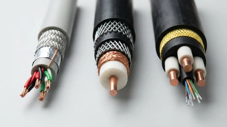
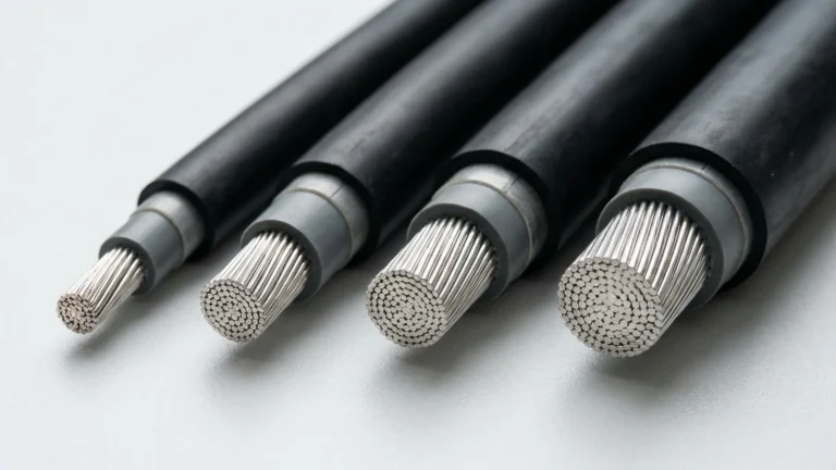
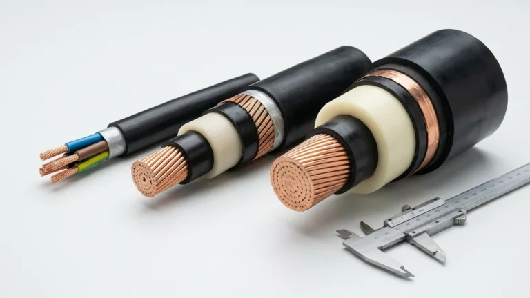
Quick answer: Protective earth (PE) conductor size in a flexible power cable is not determined by phase-conductor area alone. The responsible designer must identify the applicable installation and product rules, the protective device and prospective fault duty, the complete earth-fault path, and the cable’s termination and movement conditions. A ground-check core or metallic screen is a different function unless the approved system design expressly assigns and verifies an earth-path role.
This guide is for engineers and technical buyers specifying flexible power, reeling and trailing cables for industrial equipment. It explains the information needed to select or review a PE arrangement; it is not a universal mm²-to-earth-size chart or a substitute for the project electrical design.
What Does the PE Conductor Do?
A PE or equipment grounding conductor provides a protective connection between exposed conductive equipment parts and the relevant earthing or grounding system. It is not intended to carry the normal load current of a phase or neutral conductor. Under a fault, however, the path must support the protective action required by the system design. Continuity through the cable, connectors, terminations and machine frame matters as much as the conductor specified on a drawing. OSHA describes the path to ground for equipment as permanent, continuous and effective in its flexible-cord electrical-safety guidance.
“Earth wire,” “ground wire,” “PE” and “equipment grounding conductor” are often used in related discussions, but the governing terminology and sizing rule depend on the jurisdiction. The protective conductor inside a mobile power cable must also be distinguished from an earthing-electrode conductor, a main bonding conductor and a neutral. Treating all of these as one “ground cable size” question can lead to the wrong specification.
PE, Ground Check, Screen and Neutral: Different Jobs
| Element | Primary function | Selection question |
|---|---|---|
| Phase or line conductor | Delivers power to the load in normal operation | What current, voltage drop, thermal and short-circuit duties apply? |
| Protective earth / equipment grounding conductor | Forms the designated protective connection and fault path | What minimum section, fault duty, continuity and termination rules apply? |
| Ground-check or pilot conductor | Supports continuity monitoring in a compatible protection system | What monitor, circuit arrangement and connector pinout are approved? |
| Metallic screen or shield | Controls electric field or electromagnetic coupling, depending on the cable | Must it be bonded, and is any protective fault-path role expressly permitted and verified? |
| Neutral conductor | Provides the specified return path for normal load current | What load, harmonics and system arrangement govern its size? |
The table distinguishes functions, not universal wiring arrangements. In particular, a cable screen should not automatically be credited as the PE path because it is metallic, and a ground-check core should not be counted as the protective conductor. The approved design must establish the role and continuity of each element.
Can PE Size Be Chosen from Phase-Conductor Size Alone?
No. Phase size is relevant, but a rule-of-thumb such as “make the earth half the phase” is not a complete design method. The selected code may use a prescribed relationship, a protective-device rating or a fault-energy method under defined conditions. Material, conductor arrangement, disconnection time, available fault current, mechanical protection and terminations can change the answer. A nominal area that looks adequate on paper may still be unsuitable if the supplied cable build or connector cannot maintain the required protective path in service.
Do not use an AWG-to-mm² conversion as proof that a proposed PE is compliant. Nominal geometric area is not a complete substitution test. Likewise, normal-load ampacity answers a different question from the PE conductor’s fault-duty and protection checks.
Which Standard Governs the Earth-Conductor Check?
IEC-based low-voltage installations
IEC 60364-5-54 addresses earthing arrangements and protective conductors for low-voltage electrical installations. An IEC-based project should use the adopted edition, applicable national implementation and the actual installation conditions. The product standard, equipment instructions and protective-device study may impose additional requirements. Do not transfer a low-voltage installation shortcut directly to a medium-voltage mobile mining cable.
NEC-based installations and portable equipment
For a US project, the designer must check the adopted edition of NFPA 70 (NEC) and the provisions applicable to the actual wiring method, motor circuit or flexible cord. Equipment grounding conductor sizing under NEC Article 250 is not interchangeable with an IEC protective-conductor table. The protection-device rating, conductor arrangement and any relevant flexible-cord provisions need review; this article intentionally does not reproduce an unqualified NEC size table.
US general-industry rules add specific requirements for portable cables over 600 V under OSHA 29 CFR 1910.305(h), including provision of grounding conductors, shielding at the stated voltage threshold, and suitable connectors and strain relief. That clause has a defined US and voltage scope; it is not a worldwide PE sizing formula. Mining sites must also check the applicable mine, equipment and protection-system rules.
A Practical PE-Conductor Sizing Workflow
- Define the system. Record voltage, AC or DC arrangement, earthing method, equipment type, installation country, adopted code edition and whether the cable is fixed, occasionally flexed, reeled or trailed.
- Identify the protective device and fault case. Provide breaker or fuse details, prospective earth-fault current at the equipment, required disconnection behaviour and the engineering study used to establish them.
- Map the full protective path. Include the cable PE element, any parallel earth elements, couplers, terminations, glands, frame connection and upstream bonding. State clearly whether a screen has a separately verified protective role.
- Apply the governing sizing rule. Use the adopted IEC, NEC or project-specific method and verify the selected copper or aluminum construction against its conditions. Do not choose a smaller PE simply because the circuit’s normal load current is low.
- Check movement and damage exposure. Reeling, trailing, torsion and repeated connector handling can challenge continuity. Verify the cable design, bend path, strain relief, protection against abrasion and permitted repair method.
- Verify the supplied assembly. Compare the manufacturer’s exact conductor schedule, drawing and termination plan with the approved design. Test and commission the protective path according to the site procedure.
The result should be a documented requirement—such as the approved PE arrangement and minimum cross-section for this circuit—not a generic recommendation inferred from a photograph or a product name. For the normal-load conductor, use the separate amps-to-cable-size workflow; both decisions must be reconciled in the final cable assembly.
Why Flexible and Reeling Duty Need Extra Attention
A stationary conductor-size calculation does not describe the entire life of a moving cable. The PE may be one core, several distributed earth conductors or another expressly approved construction. The route can include drums, rollers, S-bends, festoons, trailing contact and detachable couplers. Engineers should ask how each PE element is protected, terminated and kept electrically continuous throughout the permitted motion and maintenance cycle.
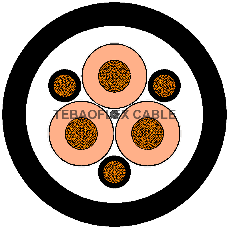
Where several earth conductors share the protective function, the project documents should say how their combined arrangement is assessed and how each is terminated. Do not silently substitute a one-earth-core cable for a distributed-earth design. For a product-level example of three phase and three earth conductors, see the (N)TSCGEWÖU MT medium-voltage reeling cable; confirm the selected build and project requirements before ordering.
Why Ground Check Does Not Replace PE
A ground-check circuit monitors the integrity of a designated grounding path; it does not remove the need for the path itself. In mining trailing-cable systems, the monitor, pilot conductor, connectors and machine connection must operate as one approved protection system. The US Mine Safety and Health Administration’s grounding guidance describes monitors that detect loss of grounding-conductor continuity and trip the feeding breaker. The exact requirement depends on the mine and jurisdiction.
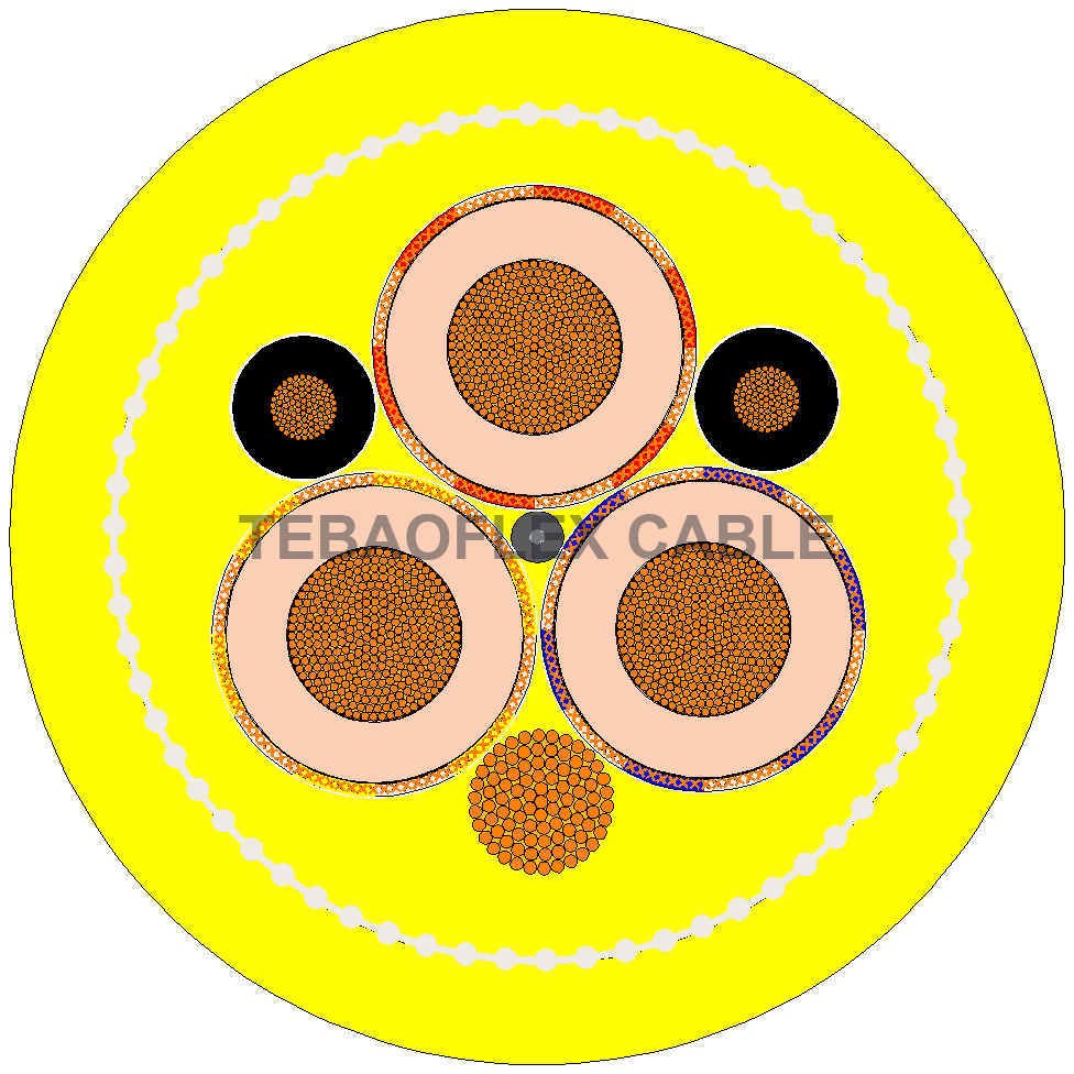
The (N)TSCGECEWÖU-GCC product documents three phase conductors, two earth conductors and one ground-check conductor in its stated configuration. That is a construction example, not a universal PE-size rule. For a US Type G-GC context, our Type G-GC ground-check selection guide explains the additional monitor and connector information needed in an RFQ.
Two Specifications That Need Different Answers
Industrial low-voltage motor feed: The buyer may know the motor rating and the length of a flexible feeder. That is enough to start the phase-conductor and voltage-drop checks, but it does not establish the PE size. The RFQ still needs the adopted wiring rules, protection-device data, fault study, termination method and cable movement class.
Medium-voltage reel-fed mining machine: The required cable schedule may include multiple earth elements and a separate monitoring core. In addition to voltage and power-core area, the reviewer needs the mine’s approved grounding and ground-check scheme, reel geometry, coupler pinout, fault-duty basis and repair procedure. A low-voltage building-installation table is not a substitute for this system review.

What to Include in a PE-Conductor Cable RFQ
| Information to supply | Why it matters |
|---|---|
| Country, site rules and adopted standard edition | Establishes the applicable PE sizing and installation basis. |
| System voltage, earthing arrangement and equipment | Identifies the protection system and appropriate cable family. |
| Phase-core count, material, area and design current | Defines the power circuit; this alone does not set PE size. |
| Protective device, prospective fault current and clearing requirement | Supports the engineer’s protective-conductor and fault-duty verification. |
| Specified PE arrangement, screen function and ground-check requirement | Prevents confusion between fault path, shielding and monitoring. |
| Route, movement, reel or festoon dimensions, connectors and length | Checks mechanical suitability and continuity at every interface. |
| Approved drawing, tests, quantity and destination | Allows a build-specific technical review and quotation. |
TEBAOFLEX can compare a proposed flexible-cable construction with the approved conductor schedule and application details supplied by the customer. The responsible engineer remains responsible for the electrical protection design and local-code approval. Send the information above through Contact Us / Send Your Requirements to request a construction review and quotation.
Frequently Asked Questions
Is the PE conductor always the same size as the phase conductor?
No. Some rules and constructions may require the same area under stated conditions; others use a different basis. Confirm the adopted standard, fault duty, material and cable arrangement instead of applying one ratio to every installation.
Can a cable screen act as the grounding conductor?
Only where the governing rules and approved system design permit and verify that role. Screen coverage or the presence of metal alone does not establish fault-current capability, continuity through joints or compliant termination.
Does a ground-check core carry the equipment earth-fault current?
A ground-check or pilot core is used for the specified monitoring circuit. Do not treat it as a substitute for the designated protective earth path; verify both against the approved cable and protection-system drawings.
What if the PE size is not yet known at quotation stage?
State it as an open engineering item. Send the protection data and a proposed cable schedule for review, but do not label a provisional cross-section as code-compliant until the responsible designer has completed the applicable checks.
Source and Scope Notes
Primary references: IEC 60364-5-54 publication scope; NFPA 70 (NEC) official publication; OSHA 29 CFR 1910.305; and MSHA grounding technical guidance. These sources address different scopes and jurisdictions. Check the adopted edition, local law, equipment documentation and project approval before using any sizing method.