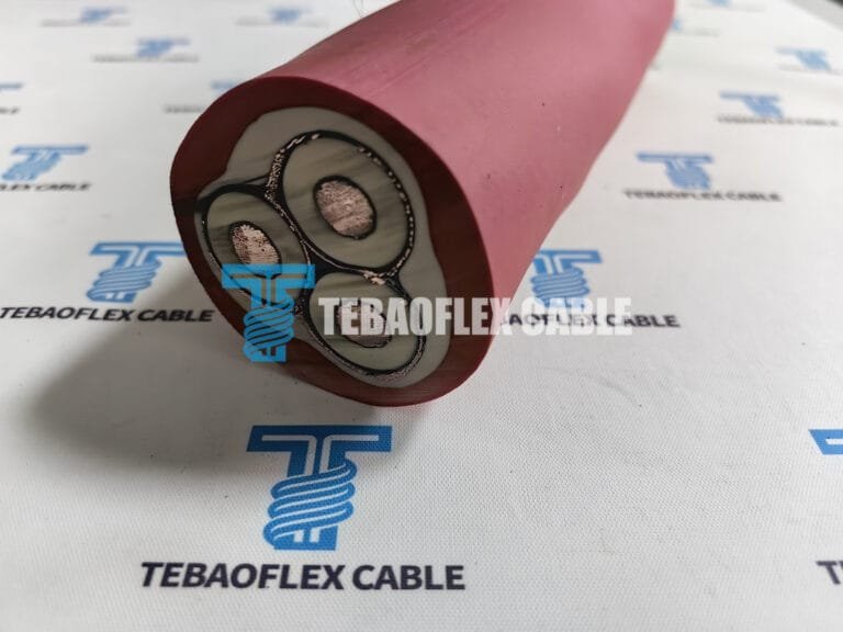
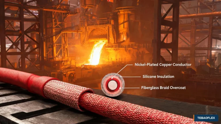
A Polish minerals company needed a low-voltage reeling cable for the drum system of a bucket-wheel stacker-reclaimer. The cable would not remain static: it had to wind and unwind with the machine, fit the available reel geometry, remain visible in a busy mining area, and support inspection before shipment. This case explains how the project team translated those operating conditions into two project-specific (N)SHTOEU-J 0.6/1 kV reeling cable configurations and a practical factory acceptance plan.
The key lesson is that conductor size and voltage are only the starting point. For a cable reel on large material-handling equipment, the engineer must also confirm the movement cycle, reel dimensions, allowable cable diameter, installation route, mechanical exposure, ambient conditions and acceptance documents. That application-led approach is also used across our mining cable solutions. For the corresponding product family, review the (N)SHTÖU-O/J 0.6/1 kV heavy-duty reeling cable; the project configuration, reel geometry and acceptance criteria must still be confirmed against the approved order documents.
Project requirements at a glance
A bucket-wheel stacker-reclaimer continuously stacks, reclaims and transfers bulk materials such as coal, ore or aggregate. Its cable reel must manage electrical power while the machine travels along the stockyard. The cable therefore becomes part of a moving system rather than a standalone product.
| Project item | Confirmed project input | Engineering significance |
|---|---|---|
| Destination and user | Poland; minerals-industry end user | Outdoor weather, winter conditions and site handling had to be reviewed |
| Equipment | Bucket-wheel stacker-reclaimer cable drum | Repeated winding, unwinding and machine travel |
| Rated voltage | 0.6/1 kV | Electrical tests and insulation system must match the agreed specification |
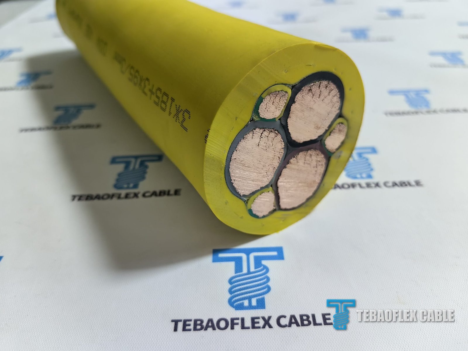
| Configuration 1 | 3 × 70 + 3 × 35/3 mm² | Three power conductors with three divided grounding conductors |
| Configuration 2 | 3 × 185 + 3 × 95/3 mm² | Larger power section for the higher-current circuit |
| Site exposure | Cold weather, moisture, rough ground and mobile equipment | Sheath, visibility, handling and protection measures matter |
| Acceptance | Factory inspection and whole-length electrical checks | Release depends on records, not appearance alone |
Why an ordinary flexible cable was not enough
A general flexible cable may bend during installation, but a reeling cable experiences repeated cyclic bending throughout operation. It may also see pulling force, changes in direction, layer pressure on the drum and occasional twist caused by imperfect cable guidance. The cable construction and the reel therefore have to be reviewed together.
For this project, the customer supplied the equipment context and maximum cable-envelope requirement. TEBAOFLEX compared the proposed constructions with the available drum space and recorded overall-diameter values for the two sizes. Those figures are project inspection values rather than universal catalogue dimensions, because conductor lay, insulation thickness, reinforcement and sheath tolerances can change the finished diameter.
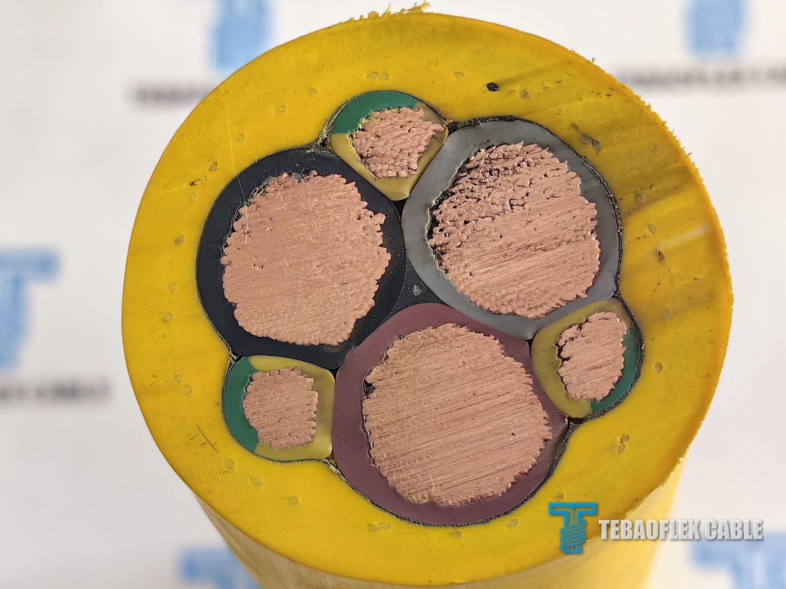
The agreed cable construction
The project specification combined a flexible conductor system with rubber insulation, a mechanically reinforced lay-up and a visible yellow sheath. The following construction describes the supplied project design; it should not be treated as a substitute for the approved drawing or data sheet for another installation.
| Layer | Project construction | Purpose in the application |
|---|---|---|
| Power conductors | Class 5 flexible tinned-copper conductors | Flexible current path for controlled reeling duty |
| Power-core insulation | EPR; brown, black and grey identification | Electrical insulation with a rubber system suited to flexible cable construction |
| Grounding conductors | Class 5 flexible tinned copper | Protective grounding arrangement distributed in the cable lay-up |
| Ground insulation | EPR; green/yellow identification | Clear protective-conductor identification |
| Core assembly | Laid-up cores with a central rubber filler | Supports a stable round construction |
| Inner sheath | Yellow PCP rubber compound, project designation 5GM5 | Provides an internal bedding and protective layer |
| Reinforcement | Aramid braided layer | Supports mechanical stability under the agreed movement and tension conditions |
| Outer sheath | Yellow PCP rubber compound, project designation 5GM5 | Visible external protection for the specified outdoor duty |
IEC 60228:2023 classifies Class 5 conductors for flexible cables and includes requirements for conductor construction and resistance. The project also referenced DIN VDE 0250-814 for the relevant rubber-insulated flexible cable family. The exact edition, test programme and compliance statement should always be confirmed in the purchase specification and signed technical documents.
Why tinned copper was selected
The base conductor requirement called for copper, while the agreed project construction used metal-coated copper strands. Tinning creates a barrier between the copper and the surrounding rubber compound during processing and provides additional protection against surface oxidation in humid handling conditions. It also gives the inspection team a visible construction feature that can be checked after a sample is stripped.
Tinned copper does not by itself guarantee flex life or corrosion performance. Strand diameter, bunching, conductor resistance, core lay, bending control, terminations and water ingress protection remain part of the complete system. During FAT, the team therefore combined visual conductor inspection with electrical measurements rather than relying on colour alone.
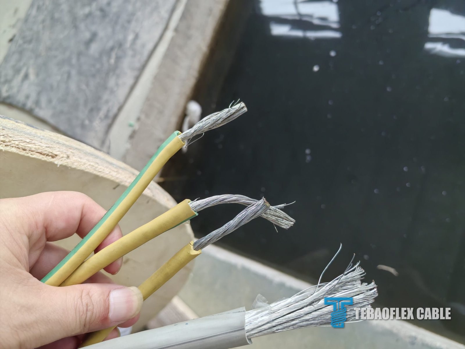
Cable diameter and reel compatibility
The reel system imposed a practical dimensional limit. Project inspection records listed an overall diameter of 44.45 mm for the 3 × 70 + 3 × 35/3 mm² construction and 63.23 mm for the 3 × 185 + 3 × 95/3 mm² construction. These figures were used for the equipment-fit discussion, but final acceptance must use the signed inspection report and the customer-approved reel drawing.
| Project configuration | Recorded overall diameter | What the equipment team must still confirm |
|---|---|---|
| 3 × 70 + 3 × 35/3 mm² | 44.45 mm | Drum groove, bending radius, fleet angle, pulling tension and termination space |
| 3 × 185 + 3 × 95/3 mm² | 63.23 mm | Drum capacity, layer build-up, bend path, reel drive torque and cable guide clearance |
Diameter alone cannot approve a reel installation. The equipment designer should check the minimum bending radius stated in the approved cable data, drum core diameter, the number of layers, the entry and exit path, speed, acceleration and maximum tensile load. Our open-pit mining cable guide explains why the complete route is more useful than a cable name alone.
Yellow sheath for visibility in the stockyard
The customer selected a yellow sheath so the cable would be easier to see around gravel, reels, service vehicles and mobile equipment. Visibility can help operators identify the cable route during inspection and handling, but colour is not a substitute for mechanical protection. Traffic crossings still require suitable cable ramps, routing controls or exclusion measures, and the cable should not be exposed to vehicle crushing.
For Polish outdoor service, the project team also considered cold weather, rain, snowmelt and wet handling. A general statement such as “cold-resistant” is not enough for final selection. The customer should specify the minimum ambient temperature, minimum moving temperature, storage conditions and reel duty so the compound and test requirements can be confirmed for the actual site.
Factory acceptance testing for the complete cable drum
The buyer wanted evidence that the cable was electrically continuous and had no hidden intermediate repair. The FAT plan therefore followed the cable from insulated-core production through the finished drum. Inspection points included in-process spark testing where applicable, visual construction checks, conductor continuity, insulation resistance, applied-voltage testing, dimensional checks and drum condition.
- Visual inspection: verify sheath colour, marking, surface condition and the absence of visible joints or repairs.
- Construction check: strip an agreed sample to confirm conductor coating, core identification and layer sequence.
- Conductor resistance: measure and correct the result to the reference temperature required by the applicable procedure.
- Continuity test: confirm each power and grounding conductor is continuous over the complete manufactured length.
- Insulation resistance: record the instrument, test voltage, temperature, cable length and measured result.
- Applied-voltage test: use the voltage and duration stated in the approved test plan, then record the signed result.
- Dimensional inspection: measure overall diameter and confirm compatibility with the approved reel design.
- Drum and packing check: verify cable end sealing, drum integrity, protective boarding, labels and release documentation.
Photographs and videos are useful evidence of the inspection process, but the instrument display in a single frame is not the acceptance record. The signed report, calibrated-equipment information and agreed test procedure control the final result. This distinction prevents a momentary reading from being mistaken for the complete test duration or final pass criteria. Buyers can review the wider document process on our certifications and test-report support page.
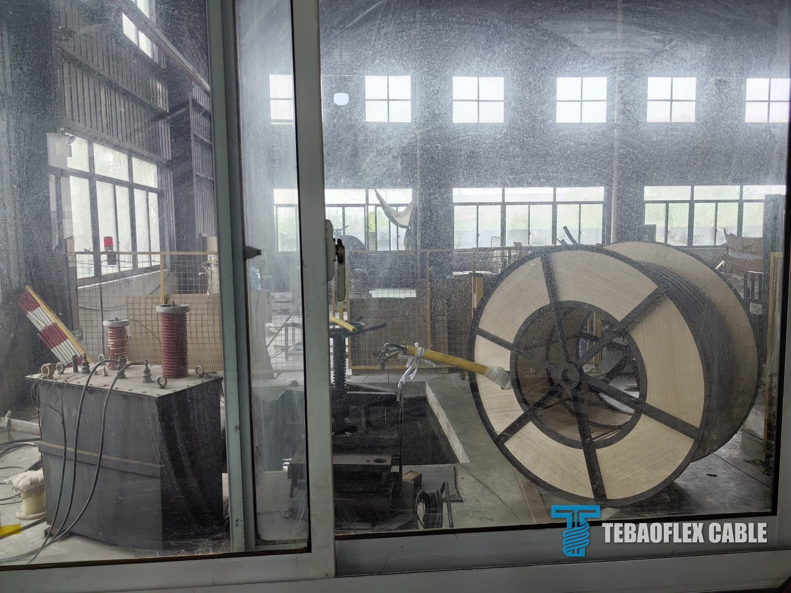
Export drum and transport planning
Heavy reeling cable places a substantial load on the delivery drum. The drum design must account for cable diameter, total length, net cable mass, flange loading and lifting method. After winding, protective boarding reduces the risk of exposed cable being struck during handling. Inside the container, the drum requires blocking and bracing so it cannot roll, slide or shift under transport forces.
Transport planning should also cover end sealing, moisture protection, lifting marks, gross and net weights, centre-of-gravity information where needed, and photo records before container closure. These steps are part of TEBAOFLEX’s custom cable and export support workflow, with the exact packing method confirmed for each order.
What procurement teams should send for a similar project
A useful reeling-cable enquiry should describe the machine and movement rather than only requesting a model number. For a bucket-wheel stacker-reclaimer or comparable mobile material-handling machine, send the following information:
- Rated voltage, current or load data, conductor configuration and required length.
- Equipment type, reel drawing, drum core diameter, available flange width and maximum cable envelope.
- Reeling speed, acceleration, travel distance, duty cycle, number of layers and maximum pulling tension.
- Minimum ambient, installation and moving temperatures, plus exposure to water, oil, sunlight, gravel or chemicals.
- Required standard, inspection plan, documentation language and destination-market requirements.
- Termination drawing, connector or gland details, packing limits and requested delivery schedule.
If the route or reel data is incomplete, start with the machine drawing and operating description. TEBAOFLEX can then review whether an existing industrial cable product is suitable or whether a project-specific construction is needed.
Project conclusion
This Polish bucket-wheel stacker-reclaimer project required more than a large 0.6/1 kV flexible cable. The final proposal connected conductor construction, rubber materials, reinforcement, visible sheath colour, finished diameter, reel fit, whole-length FAT and export-drum protection. That sequence gives the equipment manufacturer and end user a clearer basis for technical review before installation.
For a similar mining or material-handling project, send the reel drawing, voltage, conductor size, movement data, environmental limits and required tests through the TEBAOFLEX contact form. Our team will review the complete application and prepare a cable construction for technical discussion.
Frequently asked questions
Is (N)SHTOEU-J the same as a general rubber flexible cable?
No. The project construction was reviewed for a cable-reel duty with flexible conductors, rubber insulation and sheath layers, reinforcement and a specific core arrangement. A general rubber cable should not be substituted without checking the movement, reel and test requirements.
Can reel compatibility be approved from cable diameter alone?
No. Overall diameter is necessary, but the design review also needs minimum bending radius, drum core diameter, reel capacity, fleet angle, speed, acceleration, tension and the full cable path.
Why did this project use tinned copper conductors?
The agreed design used metal-coated flexible copper strands to suit the rubber cable construction and humid industrial handling conditions. Final suitability still depends on the complete conductor, insulation, sheath, termination and operating system.
Which FAT records should a buyer request?
Request the approved inspection and test plan, conductor and dimensional records, continuity and insulation-resistance results, applied-voltage record, calibrated-instrument details, visual inspection record, drum and packing checklist, and any project-specific certificates or declarations.
Technical references: IEC 60228:2023 Conductors of Insulated Cables; DIN VDE 0250-814 standard listing. Always confirm the applicable edition and contractual requirements for the specific order.