

Application & Underground Mining Service
MGM 110 is a 110 V underground mine signaling and voice-communication cable family manufactured to Turkish TTK MGM 110/1984, combining 1.5 mm² Class 2 tinned copper conductors, PVC core insulation, and single or double galvanized steel wire armour for deep shafts and gassy roadways.
Shaft Hoist & Haulage Signaling
Multi-core configurations from 2×1.5 mm² up to 91×1.5 mm² carry shaft-bell signals, cage-interlock circuits, conveyor pull-cord trips, and ventilation monitoring telemetry across underground levels.
Twisted-Pair Underground Telephony
Balanced twisted-pair formations from 1x2x1.5 mm² to 61x2x1.5 mm² minimize inductive crosstalk for intrinsically safe mine dispatcher telephones, intercom trunks, and emergency refuge-chamber voice lines.
Selectable SWA or DWA Armouring
Single-layer GSW armour (SWA) protects horizontal gallery tray runs, while twin-layer GSW armour (DWA) delivers vertical self-supporting tensile strength and severe rockfall crush protection in deep shafts.
Unified SWA & DWA Specification: Specify Single-Armoured (SWA) for horizontal drift brackets (min. bend radius 8 x OD) or Double-Armoured (DWA) for vertical shaft drops and high-impact haulage ways (min. bend radius 9 x OD).
Cable Construction & Layer Anatomy
Engineered under Turkish standard TTK MGM 110/1984 for humid, corrosive hard-coal shafts, every signal core and telephone pair uses tin-plated 7/0.50 mm copper conductors insulated with 0.5 mm flame-retardant PVC, cushioned inside an extruded PVC bedding beneath heavy galvanized steel wire armour and special PVC.
| Layer / Component | Material & MGM 110/1984 Engineering Specification |
|---|---|
| 1. Conductor | Electrolytic circular stranded tinned copper wire per IEC 60228 Class 2: 1.5 mm² nominal cross-section (7 x 0.50 mm stranding, 1.50 mm nominal conductor diameter) for moisture corrosion immunity and reliable Krone/screw termination. |
| 2. Core Insulation & Pairing | 0.5 mm nominal PVC insulation wall yielding 2.36–2.64 mm insulated core diameter. Concentrically stranded as single cores (2–91C Signal) or twisted into balanced pairs (1–61P Telephone). |
| 3. Inner Bedding | Extruded PVC inner sheath (1.0 mm to 1.6 mm nominal wall depending on core count) forming a firm mechanical cushion beneath the steel armour wires. |
| 4. Galvanized Steel Wire Armour | Single concentric layer (SWA: 0.9 mm to 2.5 mm wires) or double counter-wound layer (DWA: 2×0.9 mm to 2×2.5 mm wires) of galvanized steel round wires, with optional galvanized steel binder tape. |
| 5. Outer Sheath | Heavy-duty special flame-retardant PVC compound (1.4 mm to 2.6 mm radial thickness) resistant to acidic mine water, mineral oils, and mechanical abrasion. |
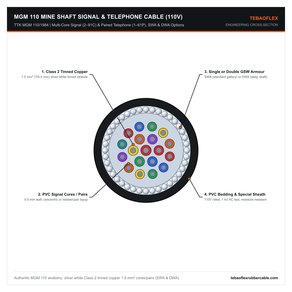
MGM 110 Cross-Section: Concentric layers of 1.5 mm² (7/0.50 mm) Class 2 tinned copper PVC cores or twisted pairs, extruded PVC bedding, single or double GSW wire armour, and special mining PVC jacket.
Technical Characteristics
TTK MGM 110 standardizes a rugged 1.5 mm² (7/0.50 mm) tinned copper conductor gauge and 1 kV AC dielectric test across all 22 core and pair counts so underground signaling relays and dispatcher telephone loops maintain low loop resistance over multi-kilometer shaft distances.
| Parameter | MGM 110/1984 Rated Value |
|---|---|
| Reference Standard | Turkish Hard Coal Enterprises TTK MGM 110/1984 & IEC 60228 Class 2 |
| Rated Operating Voltage | 110 V (Signaling, Telemetry, Bell & Underground Telephone Circuits) |
| Routine Dielectric Test | 1000 V (1 kV) AC |
| Unit Conductor Geometry | 1.5 mm² Tinned Copper (7 / 0.50 mm, nom. Ø 1.50 mm; Core OD 2.36–2.64 mm) |
| Signal Core Counts | 2, 4, 7, 10, 12, 14, 19, 37, 61, and 91 cores x 1.5 mm² |
| Telephone Pair Counts | 1, 2, 4, 7, 10, 12, 19, 27, 30, 37, 48, and 61 pairs x 2 x 1.5 mm² |
| Minimum Bending Radius | 8 x Max. OD (Single-Layer Armour SWA) | 9 x Max. OD (Double-Layer Armour DWA) |
| Installation Environment | Fixed installation in deep gassy coal shafts, inclined drifts, haulage roadways, and surface headframes |
Dimensional, Armour & Weight Specifications (SWA & DWA)
All four verified TTK MGM 110/1984 dimensional schedules are tabulated below, covering single-armoured (SWA) and double-armoured (DWA) builds with inner/outer sheath walls, wire gauges, diameter tolerances, bending radii, and copper/cable masses for both mine signaling (2×1.5–91×1.5 mm²) and telephone trunks (1x2x1.5–61x2x1.5 mm²).
1. MGM 110 Signal Cable — Single-Layer Galvanized Steel Wire Armour (SWA, 2×1.5 to 91×1.5 mm²)
| Cable Size | Inner Sheath (mm) | SWA Wire Dia. (mm) | Outer Sheath (mm) | Min. OD (mm) | Max. OD (mm) | Min. Bend (mm) | Copper Wt. (kg/km) | Cable Wt. (kg/km) |
|---|---|---|---|---|---|---|---|---|
| 2×1.5 | 1.0 | 1 x 0.90 | 1.4 | 11.6 | 13.0 | 104 | 30 | 320 |
| 4×1.5 | 1.0 | 1 x 0.90 | 1.5 | 12.8 | 14.4 | 116 | 60 | 395 |
| 7×1.5 | 1.0 | 1 x 0.90 | 1.5 | 14.2 | 15.8 | 127 | 105 | 500 |
| 10×1.5 | 1.0 | 1 x 1.25 | 1.6 | 17.7 | 19.3 | 155 | 150 | 750 |
| 12×1.5 | 1.0 | 1 x 1.25 | 1.6 | 18.1 | 19.7 | 158 | 180 | 850 |
| 14×1.5 | 1.0 | 1 x 1.25 | 1.6 | 18.6 | 20.6 | 165 | 210 | 950 |
| 19×1.5 | 1.0 | 1 x 1.25 | 1.7 | 20.2 | 22.2 | 178 | 280 | 1100 |
| 37×1.5 | 1.2 | 1 x 1.60 | 1.8 | 26.5 | 28.9 | 232 | 540 | 1900 |
| 61×1.5 | 1.2 | 1 x 1.60 | 2.0 | 32.1 | 34.5 | 276 | 880 | 2740 |
| 91×1.5 | 1.4 | 1 x 2.00 | 2.2 | 38.5 | 41.3 | 331 | 1315 | 4050 |
2. MGM 110 Signal Cable — Double-Layer Galvanized Steel Wire Armour (DWA, 2×1.5 to 91×1.5 mm²)
| Cable Size | Inner Sheath (mm) | DWA Wire Dia. (mm) | Outer Sheath (mm) | Min. OD (mm) | Max. OD (mm) | Min. Bend (mm) | Copper Wt. (kg/km) | Cable Wt. (kg/km) |
|---|---|---|---|---|---|---|---|---|
| 2×1.5 | 1.0 | 2 x 0.90 | 1.5 | 15.9 | 17.3 | 156 | 30 | 570 |
| 4×1.5 | 1.0 | 2 x 0.90 | 1.6 | 17.0 | 18.6 | 168 | 60 | 680 |
| 7×1.5 | 1.0 | 2 x 0.90 | 1.6 | 17.5 | 19.1 | 172 | 105 | 820 |
| 10×1.5 | 1.0 | 2 x 1.25 | 1.7 | 22.8 | 24.4 | 220 | 150 | 1280 |
| 12×1.5 | 1.0 | 2 x 1.25 | 1.7 | 23.2 | 24.8 | 224 | 180 | 1350 |
| 14×1.5 | 1.0 | 2 x 1.25 | 1.7 | 23.8 | 25.8 | 233 | 210 | 1450 |
| 19×1.5 | 1.0 | 2 x 1.25 | 1.8 | 25.3 | 27.3 | 246 | 280 | 1650 |
| 37×1.5 | 1.2 | 2 x 1.60 | 1.9 | 32.5 | 34.9 | 315 | 540 | 2850 |
| 61×1.5 | 1.2 | 2 x 1.60 | 2.1 | 37.7 | 40.1 | 361 | 880 | 3000 |
| 91×1.5 | 1.4 | 2 x 2.00 | 2.3 | 45.1 | 47.9 | 432 | 1315 | 5600 |
3. MGM 110 Telephone Cable — Single-Layer Galvanized Steel Wire Armour (SWA, 1x2x1.5 to 61x2x1.5 mm²)
| Pair Size | Inner Sheath (mm) | SWA Wire Dia. (mm) | Outer Sheath (mm) | Min. OD (mm) | Max. OD (mm) | Min. Bend (mm) | Copper Wt. (kg/km) | Cable Wt. (kg/km) |
|---|---|---|---|---|---|---|---|---|
| 1x2x1.5 | 1.0 | 1 x 0.90 | 1.4 | 11.6 | 13.0 | 104 | 30 | 320 |
| 2x2x1.5 | 1.0 | 1 x 0.90 | 1.5 | 12.8 | 14.4 | 116 | 60 | 395 |
| 4x2x1.5 | 1.0 | 1 x 1.25 | 1.6 | 17.6 | 19.3 | 155 | 120 | 690 |
| 7x2x1.5 | 1.0 | 1 x 1.60 | 1.7 | 20.5 | 22.5 | 180 | 210 | 900 |
| 10x2x1.5 | 1.2 | 1 x 1.60 | 1.7 | 27.0 | 28.0 | 224 | 290 | 1350 |
| 12x2x1.5 | 1.2 | 1 x 1.60 | 1.7 | 27.3 | 28.9 | 232 | 350 | 1460 |
| 19x2x1.5 | 1.2 | 1 x 1.60 | 1.8 | 30.5 | 32.9 | 264 | 550 | 2000 |
| 27x2x1.5 | 1.4 | 1 x 2.00 | 2.0 | 36.9 | 39.5 | 316 | 780 | 2800 |
| 30x2x1.5 | 1.4 | 1 x 2.00 | 2.0 | 37.0 | 39.6 | 317 | 870 | 3000 |
| 37x2x1.5 | 1.4 | 1 x 2.00 | 2.1 | 40.8 | 43.6 | 349 | 1070 | 3450 |
| 48x2x1.5 | 1.4 | 1 x 2.00 | 2.3 | 46.1 | 48.9 | 392 | 1390 | 4160 |
| 61x2x1.5 | 1.6 | 1 x 2.50 | 2.4 | 51.3 | 54.5 | 436 | 1760 | 5500 |
4. MGM 110 Telephone Cable — Double-Layer Galvanized Steel Wire Armour (DWA, 1x2x1.5 to 61x2x1.5 mm²)
| Pair Size | Inner Sheath (mm) | DWA Wire Dia. (mm) | Outer Sheath (mm) | Min. OD (mm) | Max. OD (mm) | Min. Bend (mm) | Copper Wt. (kg/km) | Cable Wt. (kg/km) |
|---|---|---|---|---|---|---|---|---|
| 1x2x1.5 | 1.0 | 2 x 0.90 | 1.4 | 15.9 | 17.3 | 156 | 30 | 570 |
| 2x2x1.5 | 1.0 | 2 x 0.90 | 1.5 | 17.0 | 18.6 | 168 | 60 | 680 |
| 4x2x1.5 | 1.0 | 2 x 1.25 | 1.6 | 22.7 | 24.4 | 220 | 120 | 1250 |
| 7x2x1.5 | 1.0 | 2 x 1.25 | 1.7 | 25.3 | 27.3 | 246 | 210 | 1580 |
| 10x2x1.5 | 1.2 | 2 x 1.60 | 1.9 | 32.0 | 34.0 | 306 | 290 | 2350 |
| 12x2x1.5 | 1.2 | 2 x 1.60 | 1.9 | 32.4 | 34.8 | 314 | 350 | 2550 |
| 19x2x1.5 | 1.2 | 2 x 1.60 | 2.0 | 36.2 | 38.6 | 348 | 550 | 3280 |
| 27x2x1.5 | 1.4 | 2 x 2.00 | 2.2 | 43.6 | 46.2 | 416 | 780 | 4680 |
| 30x2x1.5 | 1.4 | 2 x 2.00 | 2.2 | 44.7 | 47.3 | 426 | 870 | 4950 |
| 37x2x1.5 | 1.4 | 2 x 2.00 | 2.3 | 47.3 | 50.1 | 451 | 1070 | 5620 |
| 48x2x1.5 | 1.4 | 2 x 2.00 | 2.4 | 52.5 | 55.3 | 498 | 1390 | 6590 |
| 61x2x1.5 | 1.6 | 2 x 2.50 | 2.6 | 58.8 | 62.0 | 558 | 1760 | 8800 |
27.3 mm on 12x2x1.5 SWA and 30.5 mm on 19x2x1.5 SWA).MGM 110 Signal vs. Telephone & Armour Selection Guide
Choosing the right TTK MGM 110 configuration depends on whether your 110 V underground circuit carries discrete DC/AC shaft-bell and conveyor interlock signals or balanced voice/telemetry pairs, and whether cable routing traverses horizontal roadways (SWA) or vertical hoisting shafts (DWA).
| MGM 110 Configuration | Core Formation, Armour Architecture & Underground Mine Application |
|---|---|
| MGM 110 Multi-Core Signal — SWA | 2×1.5 to 91×1.5 mm² concentric single cores + Single GSW armour for horizontal roadway conveyor pull-cords, pump level switches, and damper status indicators. |
| MGM 110 Multi-Core Signal — DWA | 2×1.5 to 91×1.5 mm² concentric single cores + Double GSW armour for vertical shaft cage-bell signaling, shaft-gate interlocks, and steep incline control trunks. |
| MGM 110 Twisted-Pair Phone — SWA | 1x2x1.5 to 61x2x1.5 mm² balanced twisted pairs + Single GSW armour for lateral gallery telephone distribution, intercom stations, and RS-485/analog sensor loops. |
| MGM 110 Twisted-Pair Phone — DWA | 1x2x1.5 to 61x2x1.5 mm² balanced twisted pairs + Double GSW armour for main vertical shaft telecom backbones connecting surface dispatch to deep pit-bottom exchanges. |
Frequently Asked Questions (FAQ)
Below are detailed technical answers to frequent underground mine communication and shaft signaling questions regarding TTK MGM 110 core and twisted-pair identification, Single Armour (SWA) versus Double Armour (DWA) ordering codes, custom electrostatic foil screening, and intrinsically safe blue outer sheaths.
How should we specify Single Armour (SWA) vs. Double Armour (DWA) when ordering MGM 110?
State the exact core or pair formation followed by SWA (Single GSW Armour) or DWA (Double GSW Armour) — for example, “MGM 110 19×1.5 mm² DWA” for a 19-core shaft signal cable or “MGM 110 12x2x1.5 mm² SWA” for a 12-pair gallery telephone cable.
Why does MGM 110 use 1.5 mm² (7/0.50 mm) conductors instead of thin 0.5 mm² telecom wire?
Deep underground mines require low loop resistance over multi-kilometer shaft/roadway runs for intrinsically safe barriers and shaft-bell relays, plus high mechanical strand tensile strength at terminal blocks exposed to vibration.
Can MGM 110 telephone cables be supplied with an electrostatic foil screen?
Standard TTK MGM 110/1984 relies on balanced pair twist and grounded galvanized steel wire armour for interference rejection. Where VFD power cables run on adjacent brackets, TEBAOFLEX can add an overall aluminum/PET tape + tinned drain wire screen on request.
Are custom pair counts or colored outer jackets (blue for IS circuits) available?
Yes. In addition to black mining PVC, TEBAOFLEX manufactures intrinsically safe (IS) light-blue outer sheaths or high-visibility orange/yellow striping to segregate shaft communication trunks.
Need MGM 110 Shaft Signal or Underground Telephone Cables?
Specify your required core/pair count (2×1.5–91×1.5 or 1x2x1.5–61x2x1.5 mm²), SWA or DWA armouring, and drum lengths for a prompt factory quotation.
Explore All Mining & Tunneling Cables