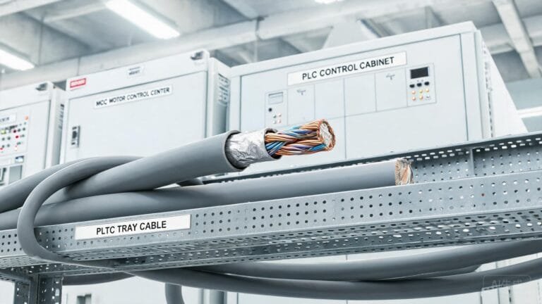
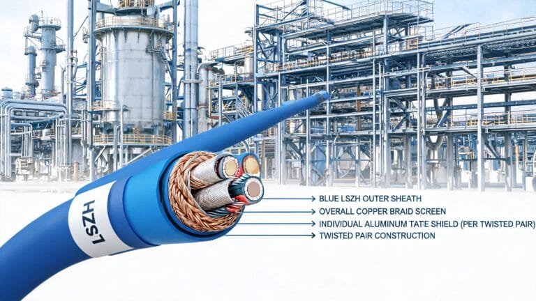
A drone charging cable is one part of an approved UAV ground-support system. Before requesting a cable, identify which cable leg is being specified, then confirm the charger output, UAV interface, continuous duty, connector system, data or interlock needs, route and environmental exposure.
First define the cable boundary
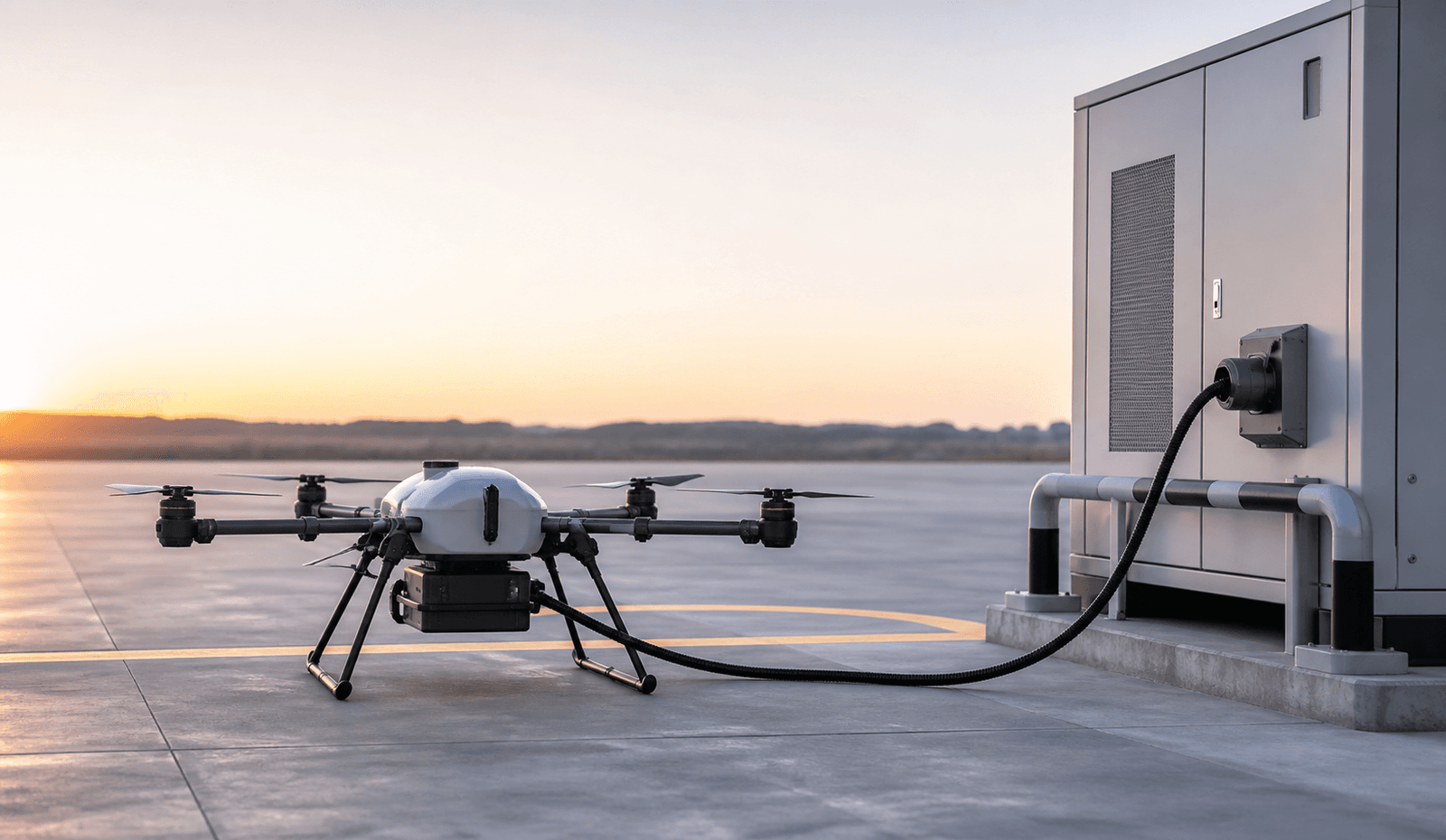
“Drone charging cable” can refer to more than one connection. The facility-supply cable feeds the charger or ground-support cabinet. The charger-output cable connects the approved charging equipment to the UAV-side interface. These two legs can have different voltage, current, connector, protective and environmental requirements, so they should not share a single generic specification.
Start with the UAV manufacturer’s approved charging documentation and the charger or ground-support equipment documentation. A cable supplier should receive those electrical and interface requirements—not be asked to infer them from the drone size, battery label or connector appearance.
UAV ground-support charging cable checklist
| Specification area | Questions to answer before RFQ | What to provide |
|---|---|---|
| Cable leg | Is this the facility supply to the charger, or the charger output to the UAV interface? | Single-line diagram and clear connection-end identification. |
| Electrical duty | What are the approved AC or DC voltage, continuous current, maximum current, duty cycle and allowable voltage-drop criteria? | Charger output data, UAV charging requirement and project electrical documentation. |
| Connector system | Which approved connector, mating half, contact arrangement, keying, sealing and strain-relief arrangement is required? | Connector model, drawing, pinout and approved assembly method. |
| Control and data | Are there interlock, enable, temperature-sense, pilot or communication conductors? | Full control/data schedule, protocol requirements and termination details. |
| Conductor and cable design | Does the route require flexibility, fine stranding, shielding, protective conductor, signal pairs or other elements? | Required core schedule and conductor size after system design. |
| Movement and routing | Will the cable be carried, reeled, guided, dragged or used on a mobile ground-support cart? | Length, bend points, travel, tension, guide hardware and service cycle. |
| Environment | What exposure is expected from rain, UV, dust, oil, cleaning fluids, temperature and vehicle traffic? | Site conditions and any ingress-protection or jacket requirements. |
| Safety and documentation | What emergency shutdown, inspection, labelling, test and acceptance requirements apply? | Project safety procedure, drawings, test requirements and applicable authority requirements. |
Connector details cannot be inferred from an image
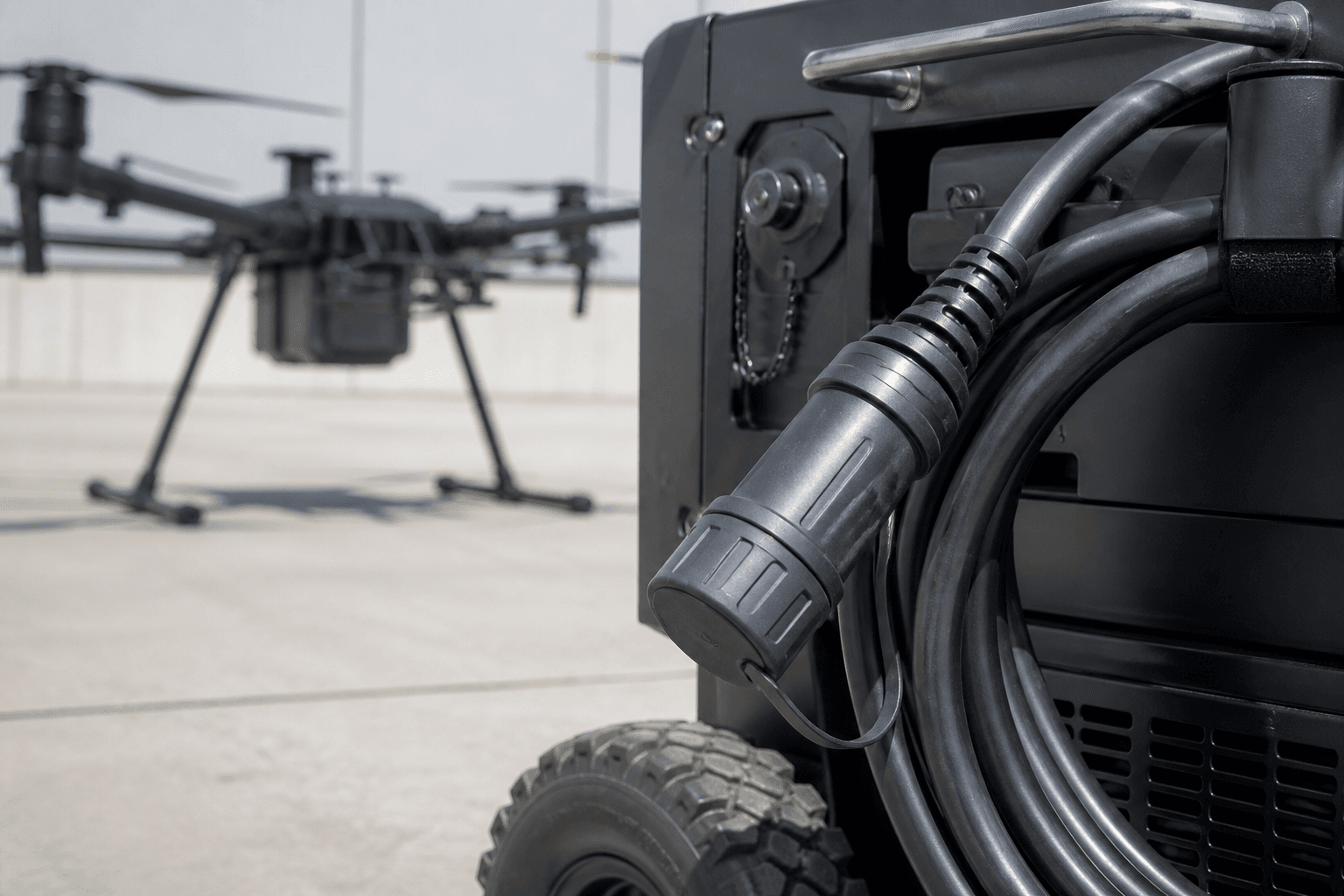
A connector can look similar while having different contact ratings, keying, sealing, data contacts or interlock functions. Record the exact mating interface and which end of the cable it serves. Include contact arrangement, connector backshell or overmould requirement, strain-relief method, mating-cycle requirement and the approved assembly or termination instructions.
Do not choose a connector or cable from a generic “charging” category. The approved UAV/charger interface defines the required electrical and functional arrangement. If the system includes communication or interlock conductors, their purpose and termination must be documented before the cable construction is selected.
Specify power, data and mechanical duty together
Conductor size cannot be selected from charging current alone. The final design also depends on voltage, length, permitted voltage drop, duty cycle, installation method, ambient temperature, grouping and connection method. Where the charging lead also carries enable, status, sensing or communication functions, those cores should be specified as part of the same approved cable schedule.
For ground-support carts and field charging stations, document whether the cable is regularly moved, wound on a reel, routed through guides or exposed to abrasion. State the required bend radius, handling frequency, tensile or strain-relief conditions and any protection needed where the cable crosses a working area.
Plan the route before selecting the jacket
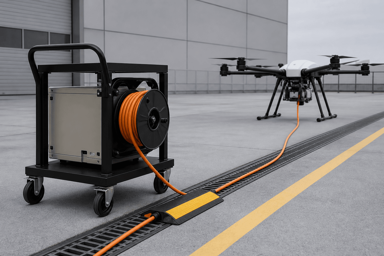
- Fixed charging bay: identify the cable path, supports, bend points and protection from vehicle or pedestrian traffic.
- Mobile ground-support cart: state the reel or storage arrangement, travel path, acceleration, wheel traffic and connector parking position.
- Outdoor use: document UV, rain, dust, temperature and cleaning exposure rather than requesting a generic “weatherproof” cable.
- Portable lead: define handling frequency, pull force, minimum bend radius and storage conditions.
Keep approval and cable supply in the right order
The UAV manufacturer and charging-system provider must approve the charging interface and operating process. The cable specification should then translate those approved requirements into conductor, insulation, shielding, jacket, connector and length details. A custom cable does not change the UAV’s approved charging limits or replace the system’s protective functions.
For a related view of ground-support cable documentation, see the Aircraft Ground Power Cable Guide. That article addresses aircraft ground-power context; it is not a UAV charging specification. For cable quality records and documentation support, review TEBAOFLEX cable certifications, test reports and laboratory support.
Frequently asked questions
Can one cable serve both facility input and UAV charging output?
Do not assume so. The facility-to-charger and charger-to-UAV cable legs can have different electrical, connector and protection requirements. Specify them separately.
Can a cable be selected from the drone battery label?
No. Use the approved UAV charging documentation and charger specifications, including the exact interface and operating conditions.
What if the charging lead includes data or an interlock?
Provide the full core schedule, pinout, protocol or functional requirement and approved termination details. Do not treat these conductors as optional additions.
Is a generic outdoor cable sufficient for a mobile charging cart?
Not without confirming movement, reel or storage arrangement, bend limits, vehicle exposure, weather and connector strain relief.
Send an RFQ-ready UAV cable brief
Send TEBAOFLEX your UAV ground-support charging cable requirements, including the approved electrical data, connector drawings, core schedule, length, route, environmental conditions and documentation needs. We can review the cable construction request before quotation.