

Application & Underground Mining Service
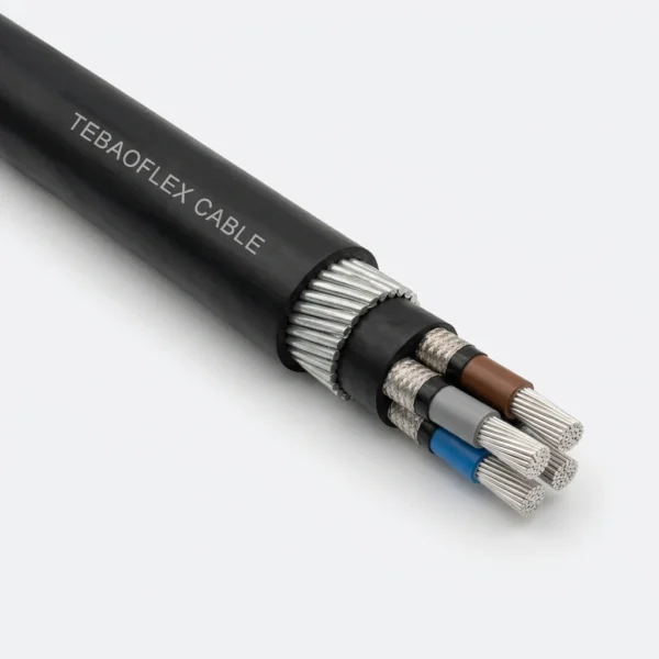
MGM 111 Type 320 and Type 321 are 1900/3300 V pliable-armoured elastomeric mining cables engineered to Turkish TTK MGM 111/1985, combining Class 5 tinned copper conductors, 3.0 mm EPR insulation, copper/nylon braided core screens, and stranded galvanized steel armour for semi-mobile coal-face feeders.
Advancing Longwall Substation Feeders
Pliable 7-wire galvanized steel rope strands (7/0.70 mm to 7/1.25 mm) allow repeated roadway relocation as longwall faces advance without the kinking or birdcaging of rigid SWA shaft cables.
Composite Copper/Nylon Core Screens
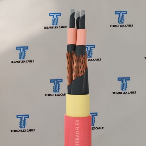
Each 3.3 kV insulated core is enclosed in semiconducting elastomeric layers and a flexible tinned-copper/nylon composite braid screen for instantaneous earth-fault containment under flexing.
Severe Abrasion & Flame Protection
Extra-thick heavy-duty polychloroprene (PCP) outer sheathing (4.0 mm up to 7.6 mm radial wall) resists coal-floor dragging, hydraulic oil immersion, and underground fire propagation.
Type 320 vs. Type 321 Architecture: Type 320 integrates three individually screened EPR phase cores plus one uninsulated interstitial tinned copper earth core (3x16+16 to 3x120+70 mm²); Type 321 provides four equal-section individually screened EPR cores (4x16 to 4x150 mm²).
Cable Construction & Layer Anatomy
Built for harsh semi-mobile underground duty under MGM 111/1985, Type 320 and Type 321 pair fine-stranded Class 5 tinned copper conductors and thick 3.0 mm thermoset EPR dielectric walls with flexible braided metallic screens, elastomeric bedding, and stranded steel wire rope armour.
| Layer / Component | Material & MGM 111/1985 Engineering Specification |
|---|---|
| 1. Conductor | Electrolytic flexible stranded tinned copper wire per IEC 60228 Class 5 (0.40 mm wires on 16–50 mm²; 0.50 mm wires on 70–150 mm²). |
| 2. Semiconductive & EPR Insulation | 3.0 mm nominal Ethylene Propylene Rubber (EPR) insulation wall with semiconducting stress-control layers on all insulated cores (3 phase cores in Type 320; all 4 cores in Type 321). |
| 3. Core Metallic Screen & Earth | Flexible composite braid of tinned copper wires and nylon yarns applied over each insulated core. Type 320 includes one uninsulated Class 5 tinned copper earth core in direct contact with the phase screens. |
| 4. Elastomeric Inner Sheath | Extruded heavy rubber inner bedding (2.5 mm to 5.0 mm radial thickness) encapsulating the cabled core assembly. |
| 5. Pliable Steel Rope Armour | Helical armour of 7-wire galvanized steel pliable strands (7/0.70 mm, 7/0.90 mm, or 7/1.25 mm) combining high crush strength with repeatable bending flexibility. |
| 6. Outer Sheath | Heavy-duty black chloroprene rubber (PCP) jacket (4.0 mm to 7.6 mm radial wall), flame retardant, oil resistant, and tear resistant. |
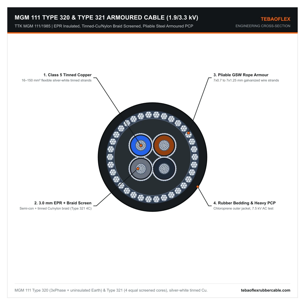
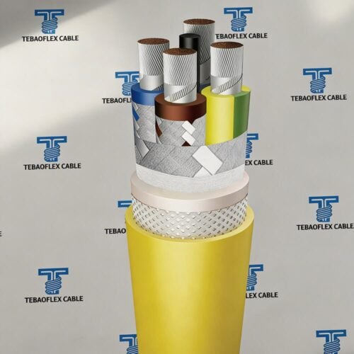
MGM 111 Type 321 Cross-Section (4-Core Screened Shown): Class 5 tinned copper conductors, 3.0 mm EPR insulation, semiconductive layers + tinned copper/nylon composite braid screens, rubber bedding, pliable 7-wire GSW rope armour, and heavy-duty PCP sheath.
Technical Characteristics
Turkish standard TTK MGM 111/1985 mandates a 7.5 kV AC routine dielectric test and strict maximum DC resistances across Class 5 phase conductors, composite copper/nylon core screens, and pliable galvanized steel armour strands to guarantee fail-safe earth-fault tripping in gassy coal seams.
| Parameter | MGM 111/1985 Rated Value |
|---|---|
| Reference Standard | Turkish Hard Coal Enterprises TTK MGM 111/1985 & IEC 60228 Class 5 |
| Rated Voltage (Uo/U) | 1900 / 3300 V (1.9/3.3 kV AC Three-Phase Mining Systems) |
| Routine Dielectric Test | 7500 V (7.5 kV) AC |
| Size Range | Type 320: 3×16+16 to 3×120+70 mm² | Type 321: 4×16 to 4×150 mm² |
| EPR Insulation Thickness | 3.0 mm nominal radial thickness across all cross-sections |
| Current Rating Basis | 85 A (16 mm²) up to 345 A (150 mm²) continuous at 25°C ambient |
| Minimum Bending Radius | 9 x maximum overall cable diameter (503 mm to 894 mm) |
| Earth-Fault Path Impedance | Low-resistance tinned Cu/nylon screen + earth core (0.70–0.18 Ω/km on Type 320) + pliable GSW armour (1.40–0.38 Ω/km) |
Dimensional, Impedance & Ampacity Specifications
The two verified TTK MGM 111/1985 engineering schedules below list IEC 60228 Class 5 conductor stranding, rubber sheath walls, 7-wire pliable steel armour gauges, outer diameter tolerances, 9x OD bending radii, 25°C current ratings, DC resistances, and masses for Type 320 and Type 321.
1. MGM 111 Type 320 (1900/3300V) — 3 Screened Phase Cores + 1 Uninsulated Earth Core (3×16+16 to 3×120+70 mm²)
| Cable Size | Phase Strand (n/mm) | Earth Size & Strand | Inner Sheath (mm) | Pliable Armour | Outer Sheath (mm) | Min. OD (mm) | Max. OD (mm) | Min. Bend (mm) | Current 25°C (A) | Phase R (Ω/km) | 3 Scr.+Earth R | Armour R (Ω/km) | Cu Wt. (kg/km) | Cable Wt. (kg/km) |
|---|---|---|---|---|---|---|---|---|---|---|---|---|---|---|
| 3×16+16 | 126/0.40 | 1×16 (126/0.40) | 2.5 | 7 / 0.70 | 4.0 | 51.5 | 55.8 | 503 | 85 | 1.24 | 0.70 | 1.40 | 990 | 4700 |
| 3×25+16 | 196/0.40 | 1×16 (126/0.40) | 2.5 | 7 / 0.70 | 5.0 | 56.7 | 60.1 | 541 | 110 | 0.795 | 0.60 | 0.96 | 1300 | 6150 |
| 3×35+16 | 276/0.40 | 1×16 (126/0.40) | 3.5 | 7 / 0.90 | 5.3 | 60.7 | 64.1 | 577 | 135 | 0.565 | 0.50 | 0.90 | 1650 | 7300 |
| 3×50+25 | 396/0.40 | 1×25 (196/0.40) | 3.8 | 7 / 0.90 | 5.8 | 68.6 | 72.3 | 651 | 170 | 0.393 | 0.50 | 0.79 | 2250 | 9100 |
| 3×70+35 | 360/0.50 | 1×35 (276/0.40) | 3.8 | 7 / 0.90 | 6.7 | 74.7 | 78.4 | 706 | 205 | 0.277 | 0.34 | 0.73 | 3150 | 11000 |
| 3×95+50 | 475/0.50 | 1×50 (396/0.40) | 5.0 | 7 / 1.25 | 6.8 | 85.3 | 89.2 | 803 | 250 | 0.210 | 0.28 | 0.47 | 4200 | 11800 |
| 3×120+70 | 608/0.50 | 1×70 (360/0.50) | 5.0 | 7 / 1.25 | 7.2 | 88.5 | 93.7 | 844 | 295 | 0.164 | 0.18 | 0.44 | 5050 | 16700 |
2. MGM 111 Type 321 (1900/3300V) — 4 Equal Individually Screened EPR Cores (4×16 to 4×150 mm²)
| Cable Size | Cond. Strand (n/mm) | EPR Wall (mm) | Inner Sheath (mm) | Pliable Armour | Outer Sheath (mm) | Min. OD (mm) | Max. OD (mm) | Min. Bend (mm) | Current 25°C (A) | Cond. R (Ω/km) | Armour R (Ω/km) | Cu Wt. (kg/km) | Cable Wt. (kg/km) |
|---|---|---|---|---|---|---|---|---|---|---|---|---|---|
| 4×16 | 126/0.40 | 3.0 | 2.5 | 7 / 0.70 | 4.0 | 51.5 | 55.8 | 503 | 85 | 1.24 | 1.40 | 1100 | 4850 |
| 4×25 | 196/0.40 | 3.0 | 2.5 | 7 / 0.70 | 5.0 | 56.7 | 60.1 | 541 | 110 | 0.795 | 0.96 | 1500 | 6400 |
| 4×35 | 276/0.40 | 3.0 | 3.5 | 7 / 0.90 | 5.3 | 60.7 | 64.1 | 577 | 135 | 0.565 | 0.90 | 2000 | 7650 |
| 4×50 | 396/0.40 | 3.0 | 3.8 | 7 / 0.90 | 5.8 | 68.6 | 72.3 | 651 | 170 | 0.393 | 0.79 | 2650 | 9500 |
| 4×70 | 360/0.50 | 3.0 | 3.8 | 7 / 0.90 | 6.7 | 74.7 | 78.4 | 706 | 205 | 0.277 | 0.73 | 3700 | 11550 |
| 4×95 | 475/0.50 | 3.0 | 5.0 | 7 / 1.25 | 6.8 | 85.3 | 89.2 | 803 | 250 | 0.210 | 0.47 | 4900 | 12500 |
| 4×120 | 608/0.50 | 3.0 | 5.0 | 7 / 1.25 | 7.2 | 88.5 | 93.7 | 844 | 295 | 0.164 | 0.44 | 5800 | 17450 |
| 4×150 | 756/0.50 | 3.0 | 5.0 | 7 / 1.25 | 7.6 | 95.4 | 99.3 | 894 | 345 | 0.124 | 0.38 | 6850 | 19000 |
7/0.70, 7/0.90, and 7/1.25 denote 7-wire stranded galvanized steel ropes laid helically over the rubber inner sheath.3.3 kV Underground Mining Feeder Selection Guide
Selecting between pliable-armoured MGM 111 Type 320, MGM 111 Type 321, and rigid steel-wire-armoured MGM 109 shaft cables depends on 3.3 kV earthing topology, insulated fourth-core or pilot requirements, and whether the feeder relocates periodically alongside advancing longwall coal-face switchgear.
| 3.3 kV Mining Cable Model | Core Architecture, Flexibility & Underground Duty Profile |
|---|---|
| MGM 111 Type 320 (This Page) | 1.9/3.3 kV | 3 Screened EPR Phase Cores + 1 Uninsulated Tinned Cu Earth Core | Pliable 7-wire GSW rope armour + PCP sheath for movable transformers and gate-end feeders. |
| MGM 111 Type 321 (This Page) | 1.9/3.3 kV | 4 Equal Individually Screened EPR Cores (4×16–4×150 mm²) | Pliable 7-wire GSW rope armour + PCP sheath where an insulated fourth earth/pilot core is required. |
| MGM 109 Type 3123 | 1.9/3.3 kV | 3 Class 2 Cu Cores + Cu-Tape Screen + Rigid Double GSW Armour (DWA) + PVC sheath for permanent vertical shafts and stationary main roadways. |
| MGM 109 Type 3023 / Type 3013 | 1.9/3.3 kV | 3 Unscreened Class 2 Cu PVC Cores + Rigid DWA (3023) or SWA (3013) for fixed shaft/roadway feeders without individual phase screens. |
Frequently Asked Questions (FAQ)
Below are practical engineering answers to common technical inquiries from underground hard-coal mine electrical engineers regarding TTK MGM 111 Type 320 versus Type 321 earthing geometry, flexible tinned copper and nylon braid screens, flameproof bolted coupler gland compatibility, and 660/1100V MGM 112 companion feeders.
When should engineers specify Type 320 versus Type 321 under MGM 111?
Choose Type 320 when your 3.3 kV distribution system bonds an uninsulated interstitial earth conductor directly to the three phase screens; choose Type 321 when switchgear protection requires four fully insulated, individually screened cores (3 phases + 1 insulated earth or pilot core) or extends up to 150 mm².
Why does MGM 111 use copper/nylon composite braid screens instead of copper tape?
Helical copper tape cracks or buckles when semi-mobile cables are coiled and dragged during longwall advances. A woven tinned-copper and nylon yarn braid flexes cleanly without damaging the 3.0 mm EPR insulation.
Can MGM 111 Type 320/321 terminate into standard flameproof mining couplers?
Yes. The calibrated outer diameter windows and 7-wire pliable galvanized steel armour strands fit standard flameproof (Ex d) mining bolted couplers and pliable-wire-armour compression glands.
Does TEBAOFLEX manufacture 660/1100V pliable armoured cables in the related MGM 112 series?
Yes. We supply the full TTK MGM 112 range including unscreened Type E2/E4/E5 as well as collectively and individually screened 660/1100V pliable-armoured coal-face cables.
Sourcing MGM 111 Type 320 or Type 321 3.3kV Pliable Armoured Cables?
Send your cross-section schedule (3×16+16–3×120+70 mm² or 4×16–4×150 mm²), coupler diameter constraints, and drum lengths for a detailed factory quote.
Explore All Mining & Tunneling Cables