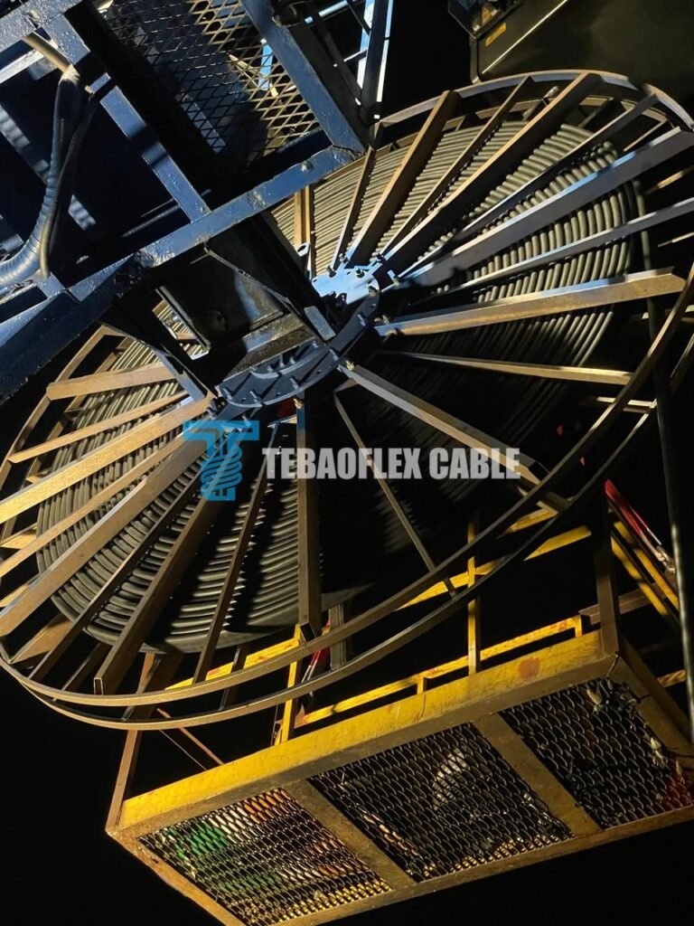
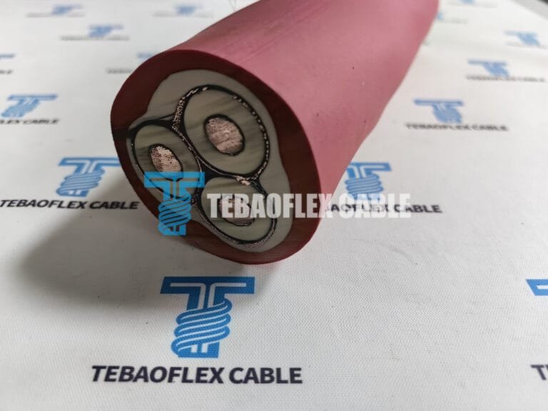
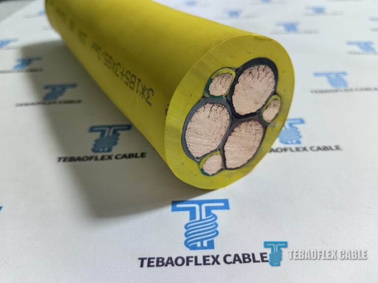
A Kazakhstan pump project needed a replacement for an existing medium-voltage submersible pump cable. The request was more specific than a voltage rating: the buyer wanted a 6/10 kV submersible pump cable replacement configured for a 180 m run, with power, protective-earth and control functions brought together in one cable. The existing pump cable and termination photographs gave the team a starting point, but the new construction still had to be agreed against the pump, entry hardware, drive system and final technical drawing.
This account follows the specification review for a proposed (N)TSCGEWCUEUS 6/10 kV cable. It reports the project requirements and acceptance questions documented during the inquiry. The site photographs show the existing equipment and cable, not a completed TEBAOFLEX installation. A signed final data sheet, production test report and installation record would be needed to report manufacturing results or field performance.
The replacement requirement in one view
The buyer described an existing pump cable that needed replacement and asked for one continuous 180 m length on a drum, without factory joints, splices or repaired sections. The proposed cable designation was TEBAOFLEX (N)TSCGEWCUEUS 6/10 kV S3×50+2×25/2+S(4×0.5) mm². This exact notation belongs in the approved drawing and purchase documentation; it should not be simplified into a different earth-core cross-section or control-core arrangement.
| Project input | Recorded requirement | What still needs approval |
|---|---|---|
| Application | Replacement cable for an industrial submersible pump in Kazakhstan | Pump model, duty, water conditions and installation route |
| Voltage | 6/10 kV (U₀/U), with a 12 kV maximum system-voltage reference in the inquiry | Final system and motor documentation |
| Length | One continuous 180 m length on one drum, without joints or repaired sections | Approved drum plan, metre marking and production-length traceability |
| Proposed designation | (N)TSCGEWCUEUS S3×50+2×25/2+S(4×0.5) mm² | Signed technical data sheet and cross-section drawing |
| Pump interface | Replacement must fit the existing cable entry and termination | Measured finished outside diameter, tolerance and gland or grommet dimensions |
| Drive system | The inquiry raised a 6 kV motor, a medium-voltage VFD, a du/dt filter and a 180 m route | Written review by the pump and drive-system responsible parties |
The customer also discussed delivery points in Kazakhstan. Because the available correspondence names more than one location, this article identifies the country without presenting a particular port or construction site as the final installation address. Commercial quotations, freight estimates and payment terms are intentionally outside this engineering case.
What the existing cable photographs can and cannot establish
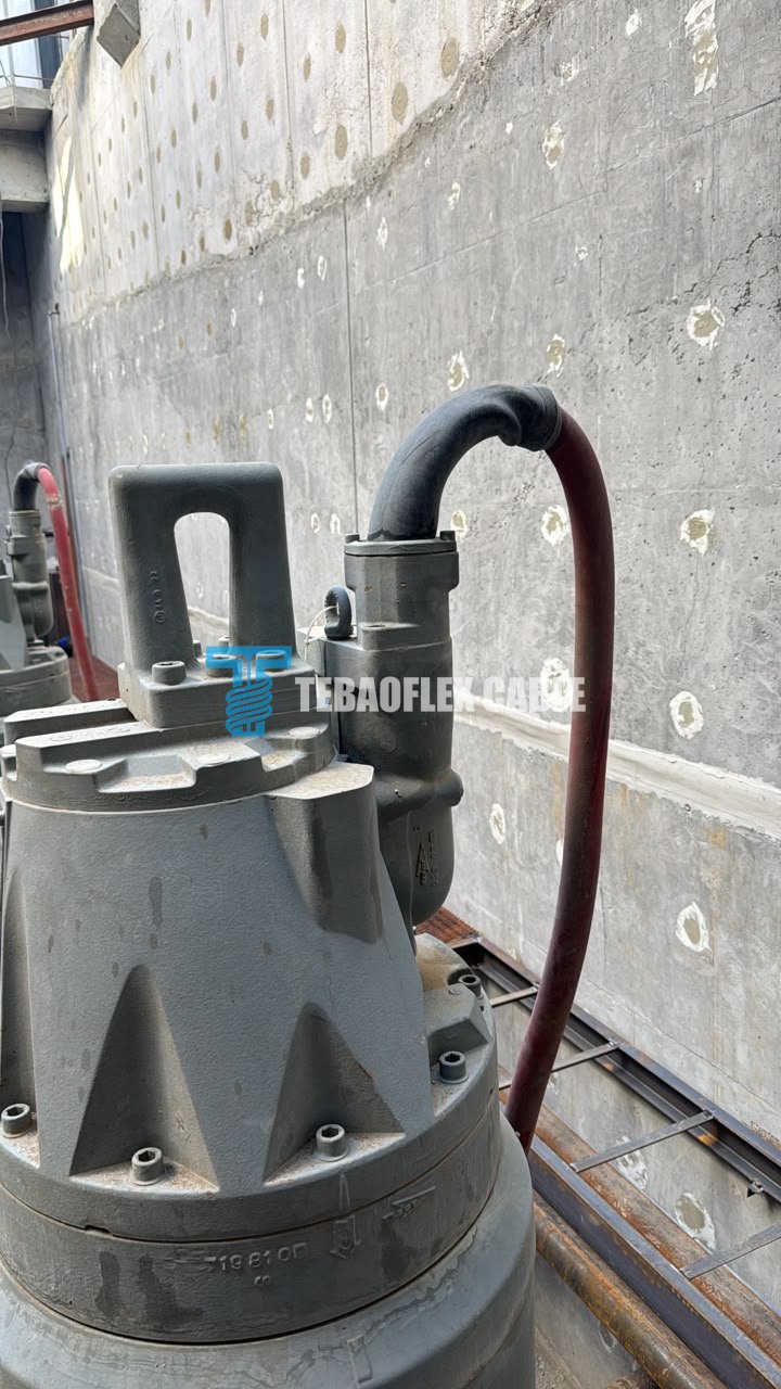
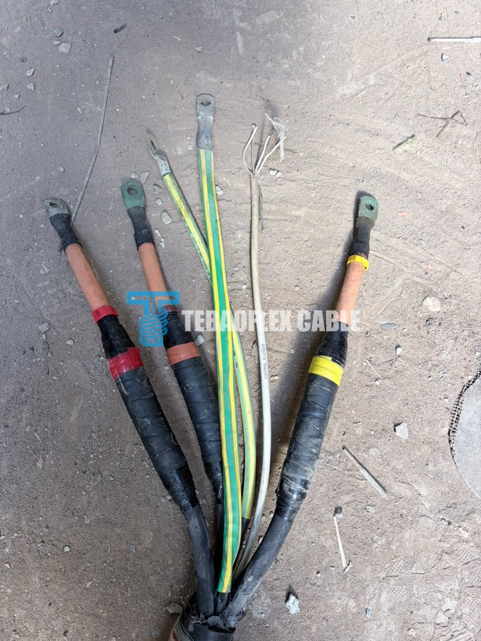
The site photographs show the pump cable entry, an opened red-sheathed cable, separated conductors and termination lugs. They are useful when discussing cable routing, available space and which electrical functions must be retained. They do not, by themselves, establish the original cable’s conductor cross-sections, insulation grade, water-depth rating or the compatibility of a new cable with the pump seal. Those details require the original cable documentation and the approved replacement drawing.
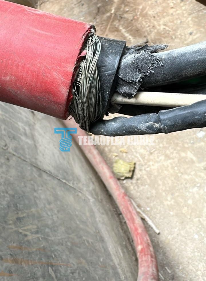
For a submersible pump, the cable entry is part of the water-tight system. An acceptable outside diameter on paper is not enough if the cable gland, grommet, strain relief or termination differs from the original arrangement. The inquiry discussed a finished diameter ceiling of 54 mm, but an actual measurement and the pump entry specification are needed before treating that figure as an achieved fit. Immersion depth, water type and whether the cable moves during operation likewise need project-specific confirmation. Our broader submersible and underwater cable application guide lists these installation inputs for buyers preparing a specification.
Why power, earth and control cores were reviewed together
The proposed designation combines three 50 mm² power paths with separately described protective-earth and control elements. The project notes discuss flexible stranded tinned-copper conductors, screened medium-voltage cores, EPR insulation, a screened control group, a tinned-copper overall braid and a PCP outer sheath. These are design inputs from the technical exchange, not a claim that every sample or production drum has been independently verified. The approved drawing must resolve the relationship between the earth-core notation 2×25/2 and the buyer’s description of two 12.5 mm² conductors.
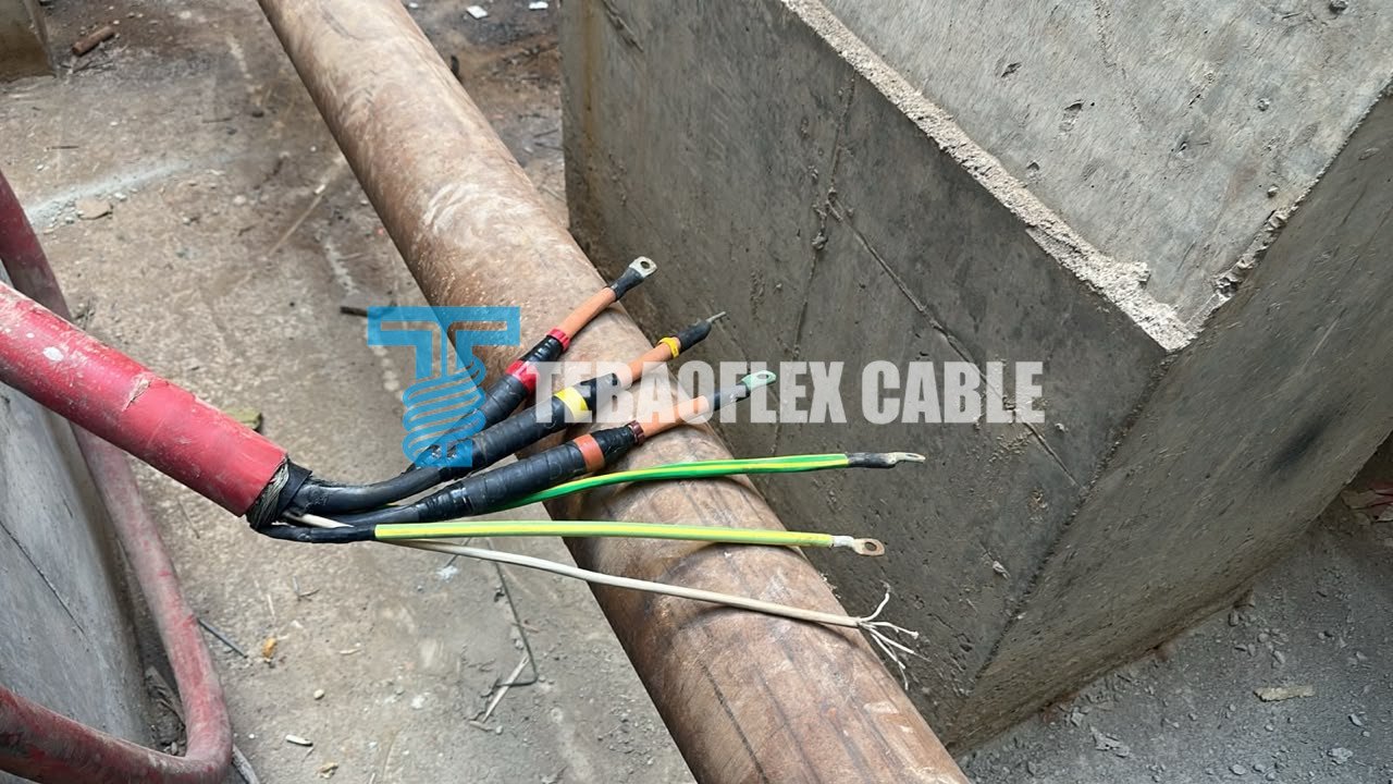
The control notation also deserves care. An early description in the exchange refers to two pairs of 0.5 mm² cores; later wording uses S(4×0.5) and states that the pair group is screened. The final drawing should identify pair grouping, screen construction, colour or number identification, connection points and the agreed control-circuit test. Without that drawing, “four control cores” could be read as four independent conductors even when the buyer expects two defined pairs.
TEBAOFLEX’s existing (N)TSCGEWCUEUS 6/10 kV product page provides the related cable family and enquiry path. This case adds the pump replacement decision: matching the delivered configuration to the specific motor, entry, route and monitoring circuit. The submersible pump cable selection guide covers the broader product category.
What a 180 m medium-voltage VFD run changes
The project correspondence asks about a 6 kV motor supplied through a medium-voltage VFD and a du/dt filter over approximately 180 m of cable. That description raises system questions; it does not establish compatibility. The drive supplier and pump manufacturer need to review the actual output waveform, filter arrangement, switching conditions, cable capacitance, insulation stress, earthing and screen termination. A cable design can have an appropriate nominal voltage while the full drive-and-motor arrangement still needs changes at the filter, termination or cable entry.
Likewise, the inquiry includes indicative capacitance and inductance figures, but no signed final data sheet or measurement report was present in the supplied folder. For a procurement decision, those values should be linked to the approved 180 m configuration and the method used to obtain them. Voltage drop and conductor heating also depend on motor current, starting behaviour, installation and ambient conditions. A generic ampacity number is not a substitute for checking the actual pump duty. TEBAOFLEX can review the cable construction and document package; system approval remains with the parties responsible for the pump and drive.
How the proposed drum should be accepted
The buyer asked to see the factory test record for the actual 180 m drum before accepting the balance of the order. Requested evidence included finished-cable and drum photographs, sheath and metre marking, measured outside diameter, whole-length continuity, conductor and screen resistance, AC withstand and partial-discharge results. Water-immersion testing was also discussed. These are acceptance requirements from the project conversation, not results shown by the site photographs.
| Acceptance item | Evidence to retain for the actual drum | Reason for checking |
|---|---|---|
| Identity and length | Approved designation, drum number, visible metre marks and production-length record | Links the supplied length to the agreed one-piece specification |
| Dimensions and cable entry | Measured finished outside diameter, tolerance and approved gland or grommet fit | Avoids an unusable pump termination |
| Conductors and screens | Continuity and resistance records for the power, earth, control and specified screen paths | Confirms the functions named in the drawing remain continuous |
| Medium-voltage insulation | Approved AC withstand and partial-discharge procedure with actual measured results | Supports electrical acceptance of the produced cable |
| Water-exposure procedure | Agreed method, duration, temperature and post-immersion test record | Prevents a general water-resistance claim from replacing the specified test |
| Release package | Signed FAT report, cable and drum photographs, marking record and final cross-section drawing | Lets the buyer compare the delivered article with the purchase specification |
The correspondence contains different descriptions of the proposed water-immersion duration and test sequence. It also discusses AC withstand and partial-discharge limits without a final report for this drum. The article therefore does not state that a 24-hour immersion, a particular voltage test or a discharge limit was passed. These claims belong only in the final agreed procedure and signed results. Buyers can review TEBAOFLEX’s testing and documentation information when preparing a project-specific acceptance list.
A replacement-cable enquiry checklist for pump owners
When a pump cable has to be replaced, start with the original pump and cable documents rather than choosing only by the jacket colour or conductor size visible in a photograph. A useful enquiry identifies the motor voltage and full-load current, pump and cable-entry model, existing cable designation, required continuous length, immersion depth, fresh or saline water, fixed or moving duty, VFD and filter details, control and monitoring circuits, termination layout, target delivery address and the tests required for the actual drum.
For this Kazakhstan request, the useful next document is the final cross-section drawing tied to the quotation and the 180 m drum acceptance plan. That makes differences in earth-core notation, control-pair screening and finished diameter visible before the cable is produced. It also keeps the distinction clear: TEBAOFLEX is specifying a replacement cable for the application and is not the original pump manufacturer’s cable supplier or an OEM-approved substitute unless the pump manufacturer confirms that status.
Frequently asked questions
Can any 6/10 kV cable replace a submersible pump cable?
No. Voltage is one input. The cable construction, water exposure, cable entry, movement, control circuits, termination and complete pump system must also match the application. The IEC 60502-2 scope description, for example, concerns specified extruded-insulation power cables for fixed installations and does not by itself establish suitability for a special submersible service. A project-specific approved data sheet and installation review are needed.
Does the 180 m requirement mean the cable has already been delivered?
No. In the material used for this case, 180 m is the requested continuous production length. Acceptance of a completed drum would require the agreed length identification, actual test results and release documents. This article records the specification stage only.
What should be confirmed before using this cable with a VFD-driven pump?
Confirm the pump maker’s cable-entry and motor requirements, the drive maker’s output and filter requirements, the exact cable length and electrical parameters, and how screens and protective-earth paths will be terminated. Written system approval is more useful than a general statement that a cable is “VFD compatible.”
Discuss a project-specific pump cable replacement
The TEBAOFLEX cable team can review a proposed medium-voltage pump cable against your equipment, route and acceptance-document requirements. Send the original cable designation or clear photographs, pump and drive data, required length, water conditions, cable-entry limits and test specification through our contact form. We can then discuss a buildable configuration and the documents needed before order release.