Project-specific high-voltage cable engineering

High Voltage DC Cable & High-Temperature Wire Solutions

Configure high voltage DC cable for power supplies, industrial X-ray equipment, medical imaging systems, lasers, electron-beam equipment, semiconductor tools, analytical instruments and pulsed-power systems. TEBAOFLEX supports unshielded, shielded, coaxial, triaxial and multi-conductor high-voltage constructions using silicone, FEP, PFA, EPR, PE and XLPE insulation options.

Voltage & waveformDC, AC and pulse duties are evaluated separately.
Temperature & materialInsulation is selected for the real operating range.
Shielding & terminationGrounding, partial discharge and interfaces are reviewed together.
Red silicone high voltage DC lead wire with stranded conductor
Start with the electrical duty—not a generic cable name.Voltage waveform, temperature, conductor size, insulation thickness, shielding and the termination interface determine the final construction.
Preliminary configuration guide

Select by Voltage, Temperature and Insulation Material

The ranges below organize configurable design directions found across the available high-voltage cable families. They do not describe one universal cable or guarantee that every voltage, material and temperature combination can be combined.

Cable familyConfigurable project rangeTypical temperature directionInsulation optionsShieldingCommon equipment use
Unshielded HV wireLow-kilovolt designs through project configurations up to approximately 150 kV DCMaterial-dependent designs from sub-zero service through high-temperature duties up to approximately +250°CSilicone, FEP, PFA, EPR, PE or XLPENoneHigh-voltage power supplies, lasers, test equipment and internal equipment wiring
Shielded / coaxial HV cableProject-specific designs from approximately 8 kV through very-high-voltage equipment connectionsSelected around dielectric, jacket and installation conditionsSilicone, FEP, EPR, PE or XLPECopper braid with optional semiconductive field-control layersPower supplies, analytical instruments, industrial inspection and controlled-field applications
Triaxial HV cableProject configurations extending into high-voltage pulse and measurement classesDependent on dielectric system and outer jacketEPR, silicone and project-specific combinationsTwo separate conductive or braided shield systemsPrecision measurement, pulse systems, research instruments and guarded circuits
X-ray / E-beam cableEquipment-specific single-core or multi-core constructions, including high-voltage classes up to approximately 320 kV DCSelected around equipment movement, cooling, jacket and terminationEPR or silicone-based high-voltage systemsSemiconductive layers and metallic braidIndustrial X-ray, medical imaging, E-beam welding and non-destructive testing equipment
Special hybrid HV cableDefined by the main HV core and auxiliary circuitsDefined by the complete compound and jacket systemPE, EPR, silicone, fluoropolymer or combined systemsOverall or individual shielding when requiredCompact machines combining HV, control, signal or auxiliary power functions

Engineering note: final rated voltage, conductor resistance, outside diameter, minimum bend radius, operating temperature, partial-discharge limit and test voltage must be confirmed against the selected construction and application.

Compact high-voltage lead wire

Unshielded High Voltage & High-Temperature Wire

Unshielded high voltage wire is typically selected where the equipment layout provides adequate separation, shielding is handled elsewhere, and a compact outside diameter is important. The conductor can be configured in fine-stranded or application-specific constructions, while the dielectric is selected according to DC voltage, continuous temperature, peak heat exposure, routing and termination method.

FEP and PFA high-voltage wire can support compact insulation systems, elevated temperatures and demanding chemical environments. Silicone high-voltage lead wire prioritizes flexibility and heat resistance. EPR, PE and XLPE designs provide additional routes for equipment that needs different electrical, mechanical or dimensional characteristics.

  • Use actual operating voltage and waveform rather than relying only on nominal equipment voltage.
  • Confirm conductor AWG or mm² size from current, voltage drop and termination requirements.
  • State whether the wire is fixed, occasionally moved or repeatedly flexed.
  • Provide the required creepage, clearance and termination geometry.

FEP & PFA HV Wire

Useful for compact high-voltage routing, elevated temperatures, instrumentation and equipment with restricted space.

Silicone HV Lead Wire

Suitable when flexibility, heat resistance and practical equipment routing are primary design requirements.

EPR High Voltage Wire

A design route for robust insulation systems, pulse duties and specialized shielded or imaging cable constructions.

PE & XLPE HV Designs

Considered for selected fixed equipment, controlled dimensions and project-specific electrical constructions.

Flexible red silicone unshielded high voltage wire with stranded conductor
Electric-field and interference control

Shielded High Voltage Cable & Coaxial Constructions

A shielded high voltage cable adds a conductive screen around the primary dielectric. Depending on the voltage class and electrical duty, the construction can include inner and outer semiconductive layers, a high-voltage insulation wall, a tinned or bare copper braid and an environmental jacket. This controlled structure can improve grounding consistency, manage the electric field and reduce interference with adjacent circuits.

Shield selection cannot be separated from grounding and termination. The equipment designer should specify whether the braid is grounded at one end or both ends, the required screen coverage, the permissible leakage or capacitance, and any partial-discharge or corona criterion. Jacket material is then selected for heat, oil, abrasion, chemical exposure and installation movement.

  • Semiconductive layers can be evaluated when smooth field control is required.
  • Copper braid material and coverage are selected around grounding and mechanical needs.
  • Silicone, fluoropolymer, PVC, TPE and other jacket routes are reviewed by environment.
  • The termination area must preserve the intended insulation and screen geometry.

For an existing related construction, review the screened silicone cable. Its published product scope is separate from the project-specific high-voltage designs described on this page.

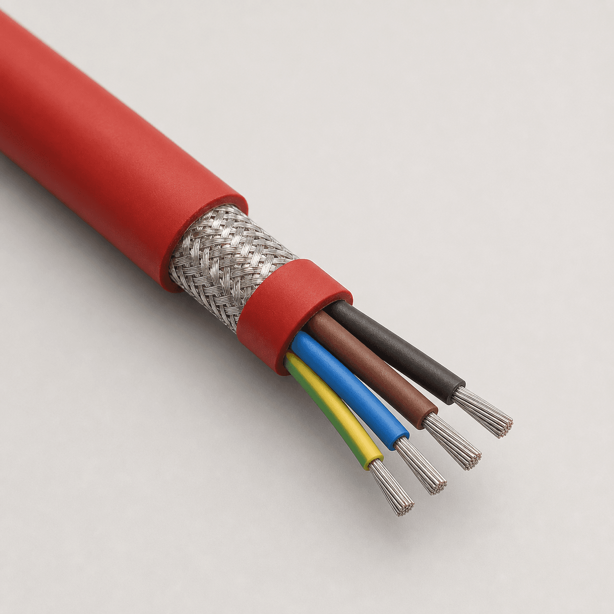
Screened silicone cable showing copper braid and insulated conductors
Specialized high-voltage constructions

Triaxial, X-ray and E-beam Cable Systems

These cable families require the electrical layers, shield functions, connector interface and test method to be designed as one system rather than selected as independent catalogue features.

Triaxial High Voltage & Pulse Cable

Triaxial high voltage cable uses more than one conductive shield layer. One layer may serve as a guard or measurement reference while the outer shield supports safety grounding and environmental screening. This arrangement is relevant to precision measurement, guarded circuits, pulsed-power equipment and scientific instruments where leakage, noise and field control must be considered together.

The enquiry should identify the role of each shield, the allowed capacitance, pulse shape, repetition rate, rise time, energy, conductor current and termination design. A DC rating alone is not enough to select a pulse cable.

X-ray & E-beam High Voltage Cable

X-ray and electron-beam cable may use one, three, four or five conductors with semiconductive layers, a high-voltage dielectric, metallic braid and a durable outer jacket. The construction is developed around the generator, tube head, equipment movement, cooling arrangement and connector or receptacle interface.

Potential applications include industrial X-ray inspection, medical imaging, computed tomography subsystems, electron-beam welding and non-destructive testing equipment. Final voltage class, core arrangement, outside diameter and bend radius remain configuration-specific.

Integrated electrical functions

Special Multi-Conductor & Hybrid High Voltage Cable

Some machines need a high-voltage circuit and auxiliary electrical functions to follow the same route. A project-specific hybrid cable can combine the main high-voltage conductor with low-voltage power, control, signal, interlock or monitoring conductors, subject to insulation coordination and system safety review.

HV + Auxiliary Power

Combine a high-voltage core with an auxiliary conductor arrangement where the circuits share a defined potential relationship and routing path.

HV + Control or Signal

Integrate control, interlock or monitoring conductors when separation, screening, capacitance and interference limits can be engineered safely.

Compact Multi-Core Design

Review conductor count, conductor size, insulation wall, fillers, shields and jacket as a complete diameter-controlled construction.

Terminated Cable Assembly

Coordinate cable length, strip dimensions, connector or receptacle interface, molded transition, identification and electrical testing.

Important design boundaryAuxiliary conductors cannot be added solely to reduce installation space. Their working potential, insulation coordination, electromagnetic compatibility, heat generation, termination and fault conditions must be evaluated before the combined construction is approved.
Insulation selection

Silicone, FEP, PFA, EPR and XLPE High Voltage Cable

Material selection balances temperature, dielectric thickness, flexibility, chemical exposure, mechanical protection, termination processing and the required outside diameter. No single compound is the best choice for every high-voltage application.

SILICONE

Flexible & Heat Resistant

Suited to high-temperature lead wire and flexible equipment routing. Mechanical protection and surface conditions must match the installation.

FEP

Compact Fluoropolymer

Supports thin, consistent insulation systems for instruments and high-voltage equipment with limited routing space.

PFA

Wide Temperature Capability

Considered for demanding high-temperature and chemical environments where the complete termination process is also compatible.

EPR

Robust HV Dielectric

Commonly evaluated for shielded, pulse, X-ray and other substantial insulation systems requiring flexibility and electrical integrity.

PE / XLPE

Stable Electrical Design

Useful in selected fixed or shielded high-voltage constructions where temperature and movement are within the confirmed design limits.

Also review the broader high-temperature and specialty cable range and the high-temperature cable application guide.

Equipment applications

Where High Voltage DC Cable Is Used

Application names help narrow the selection, but the actual cable is defined by the electrical circuit, environment, motion and equipment interface.

High-Voltage Power Supplies

Internal and external high-voltage leads for power conversion, laboratory sources and industrial equipment, configured around output voltage, current and routing.

Laser & Optical Systems

Compact high-voltage wire for laser power modules, optical inspection equipment and instruments where space and clean routing matter.

Industrial X-ray Inspection

Shielded and multi-core cable systems connecting generators, tube heads and inspection equipment for non-destructive testing.

Medical Imaging Equipment

Project-specific X-ray high voltage cable for imaging subsystems, subject to equipment safety, movement and termination requirements.

E-beam Welding

High-voltage cable for electron-beam generation equipment where shielding, vacuum-system interfaces and pulse or continuous duty must be confirmed.

Semiconductor Equipment

High-temperature and compact high-voltage leads for process, inspection and analytical tools with controlled installation environments.

Analytical Instruments

Coaxial or triaxial designs for electron microscopes, detectors and measurement systems that require managed leakage and interference.

Pulse & Research Systems

Special pulse cable for scientific equipment, electrostatic systems and test installations where waveform details drive the insulation design.

Engineering enquiry checklist

Information Needed for a High Voltage Cable Recommendation

Providing complete electrical and mechanical information reduces design iterations and helps TEBAOFLEX identify whether an existing construction can be adapted or a new project-specific cable is required.

  • Voltage and waveformOperating, peak and test voltage; DC, AC or pulse; polarity, frequency and pulse shape.
  • ConductorRequired AWG or mm², conductor material, current, number of HV cores and auxiliary circuits.
  • TemperatureMinimum, continuous and short-term peak temperature at the cable and termination.
  • Installation movementFixed, occasional movement, continuous flexing, torsion, reeling or other mechanical duty.
  • Shield and groundingShield function, grounding arrangement, coverage, capacitance and interference requirements.
  • PD and corona criteriaRequired inception or extinction limit, measurement method and acceptance conditions.
  • EnvironmentOil, chemicals, abrasion, humidity, vacuum, radiation, outdoor exposure or cleanliness requirements.
  • DimensionsMaximum outside diameter, minimum bend radius, routing space and connector entry dimensions.
  • TerminationConnector, receptacle, lug, stripped end, molded transition or customer-supplied interface drawing.
  • Commercial detailsRequired length, tolerance, quantity, reel or assembly packaging, destination and schedule.
Project documentation

Testing and Documentation for High Voltage Cable Projects

The inspection and test plan must be agreed for the selected construction. Depending on the project, the review may include conductor resistance, dimensions, insulation resistance, voltage withstand testing, shield continuity and examination of the finished termination or assembly. Partial-discharge or corona testing is included only when the required method, voltage, limits and test arrangement are defined and accepted.

Documentation should identify the approved drawing, construction revision, cable length, test conditions and traceability reference. Published configuration examples are not substitutes for the final technical specification.

No implied certification claimThis page intentionally does not assign third-party approvals, certification marks or file numbers to a cable family. Any mandatory market approval or standard must be stated in the enquiry and verified against the final product scope.
Project checkWhat must be definedWhy it matters
Dimensional inspectionConductor, insulation, overall diameter and termination dimensionsConfirms fit, clearance and construction consistency
Electrical withstandWaveform, voltage level, duration, ramp and leakage criteriaEnsures the test represents the approved cable duty
Shield continuityShield path, grounding points and assembly interfaceConfirms the intended screen and safety connection
Partial dischargeTest circuit, background noise, voltage and acceptance valueAvoids quoting a PD value without a reproducible method
Use boundary

Equipment High Voltage Cable Is Not Utility HVDC Transmission Cable

The cable families described here are primarily intended for equipment connections, high-voltage power supplies, imaging, inspection, scientific instruments, test systems and related internal or short-route applications. They should not be assumed to comply with utility, grid, submarine or long-distance HVDC transmission requirements. High-voltage equipment must be designed, installed and tested by qualified personnel using the final approved specification.

Technical FAQ

High Voltage DC Cable Questions

What is a high voltage DC cable?

A high voltage DC cable is an insulated conductor or multi-layer cable designed around a defined direct-current operating voltage. The appropriate construction depends on more than the kV value: conductor current, polarity, insulation material, temperature, electric-field control, shielding, routing, termination and test method also affect the design.

What is the difference between shielded and unshielded high voltage wire?

Unshielded wire uses the insulation surface as the outer electrical boundary and normally relies on equipment spacing and surrounding design for field management. Shielded high voltage cable adds a conductive screen, often with semiconductive layers, to provide a controlled grounded boundary. Shielding can improve field control and interference management but increases diameter, capacitance and termination complexity.

Should I choose silicone, FEP or PFA insulation?

Silicone is often considered when flexibility and heat resistance are priorities. FEP supports compact fluoropolymer insulation systems and elevated temperatures. PFA can extend the temperature and chemical-performance direction for selected projects. The choice should also consider dielectric thickness, outside diameter, movement, surface exposure and how the cable will be terminated.

Can a DC voltage rating be used for AC or pulse operation?

Not automatically. AC and pulse waveforms introduce different field stress, frequency, rise-time, repetition and heating conditions. Provide the complete waveform, peak value, duty cycle and test requirement so the insulation and screen system can be evaluated correctly.

What is a triaxial high voltage cable?

A triaxial cable has a central conductor and two separate conductive shield systems divided by insulation. It can be used where a guarded measurement circuit and an external safety or interference shield serve different functions. The role and grounding of each shield must be defined by the equipment circuit.

Can TEBAOFLEX develop X-ray or electron-beam cable?

TEBAOFLEX can evaluate project-specific cable constructions for industrial X-ray, imaging and electron-beam equipment using the required voltage, conductor arrangement, shield layers, jacket, movement and termination information. Final feasibility and values are confirmed through technical review rather than inferred from a generic family description.

Can signal or control conductors be integrated with the HV core?

They may be integrated in a hybrid cable when their potential relationship, insulation coordination, interference, heat and fault conditions are understood. Provide the circuit diagram and conductor requirements so the auxiliary cores and any individual or overall screens can be reviewed safely.

What does low partial discharge mean for a cable enquiry?

Partial discharge performance depends on the cable construction, termination, test circuit, background noise, test voltage and acceptance method. Instead of requesting “low PD” without a value, specify the measurement standard or procedure, test voltage, maximum apparent charge and whether the connector or full assembly is included.

Can a connector or molded termination be supplied with the cable?

A terminated high-voltage cable assembly can be reviewed when interface drawings, materials, creepage and clearance, strip dimensions, length, mechanical loads and test conditions are available. Connector compatibility and final assembly testing must be agreed as part of the project scope.

Is this cable suitable for utility HVDC transmission?

Not by default. This page concerns equipment, imaging, measurement, test, scientific and industrial high-voltage connections. Utility and long-distance HVDC transmission cables have separate system, installation, qualification and standard requirements and require a dedicated engineering scope.

Send Your High Voltage Cable Specification

Share the operating voltage, waveform, conductor size, temperature, shielding, movement, outside-diameter limit, termination, test criteria, length and quantity. TEBAOFLEX will review the most suitable construction route for your equipment.