A Polish mining company needed a flexible medium-voltage cable to connect a large excavator’s cable reel system with the mine power supply. The cable would repeatedly wind and unwind while carrying 12/20 kV power, so the project could not be treated as a normal fixed-cable purchase. The team had to confirm the conductor configuration, screened core construction, cable identification, dimensional checks and factory acceptance tests before shipment.
This case explains how the 12/20 kV mining reeling cable requirement was translated into an (N)TSCGECEWOEU 3 × 35 + 3 × 25/3 mm² project configuration. The customer is not named for confidentiality, and the article reports the manufacturing and pre-shipment qualification stage rather than claiming long-term field performance. Buyers considering a similar application can also review the related (N)TSCGECEWOEU cable family; the voltage, dimensions and operating limits must be confirmed for each order.
Project requirements at a glance
The excavator receives power through a moving cable reel rather than a fixed route. As the machine travels, the cable is paid out and recovered by the drum. This movement adds cyclic bending, pulling force, layer pressure and possible torsion to the electrical duty. A suitable design therefore has to be reviewed as part of the complete machine system.
| Project item | Confirmed input | Why it matters |
|---|---|---|
| Destination | Poland | Documentation, outdoor handling and site conditions require project review |
| Application | Large mining excavator cable reel and transformer connection | The cable is subject to repeated winding and machine movement |
| Cable model | (N)TSCGECEWOEU | Flexible screened medium-voltage construction for demanding mining duty |
| Rated voltage | 12/20 kV | Controls the insulation, screening and electrical test requirements |
| Configuration | 3 × 35 + 3 × 25/3 mm² | Three power cores with three divided auxiliary or earth conductors as specified |
| Release requirement | Factory acceptance testing for each production length or reel | Acceptance depends on recorded results and approved documentation |
Why the application required more than a standard MV cable
A medium-voltage cable can meet its electrical rating and still be unsuitable for a reel. Fixed installation designs are not automatically intended for thousands of winding cycles, tension from a moving machine or changes in bending direction. The equipment designer must consider the drum core diameter, minimum bend radius, number of layers, travel distance, reeling speed, acceleration, pulling force and cable guide geometry.
The mine environment adds other constraints. Abrasion, dust, wet handling, oil exposure, uneven ground and outdoor temperature changes can all affect the sheath and termination system. The correct cable cannot be selected from voltage and conductor size alone. TEBAOFLEX therefore treats the cable route and movement data as essential inputs, consistent with the application-led approach used across our mining cable solutions.
The selected (N)TSCGECEWOEU construction
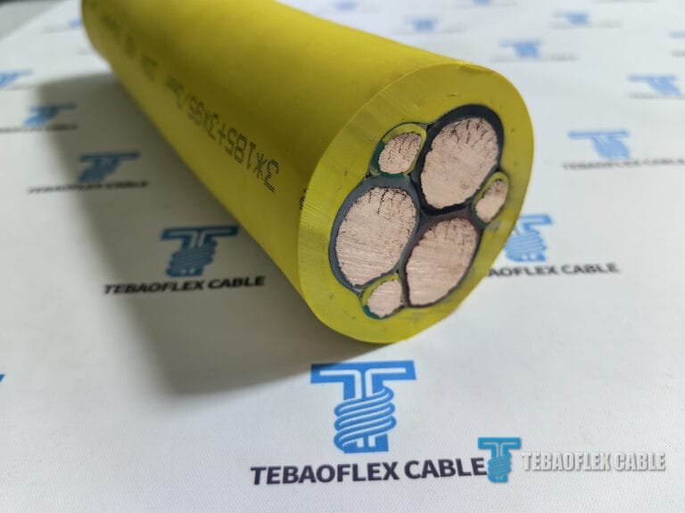
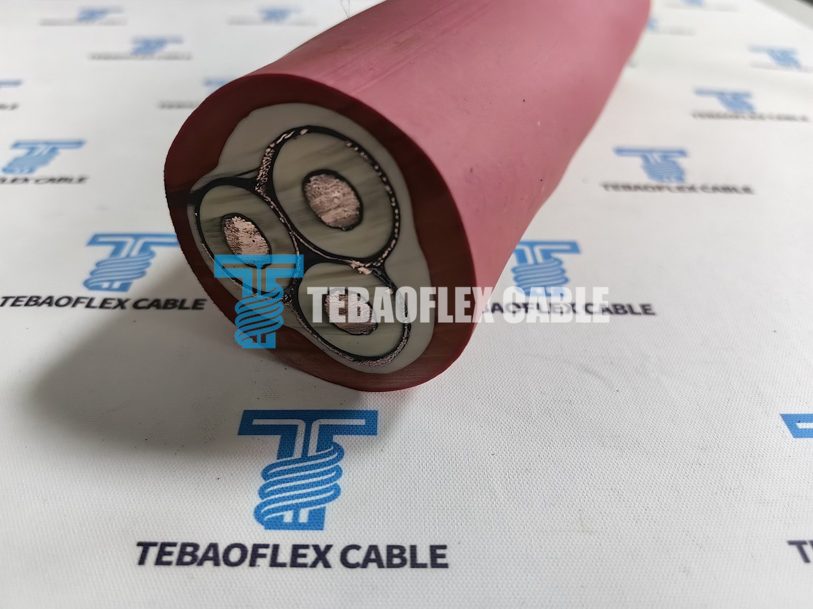
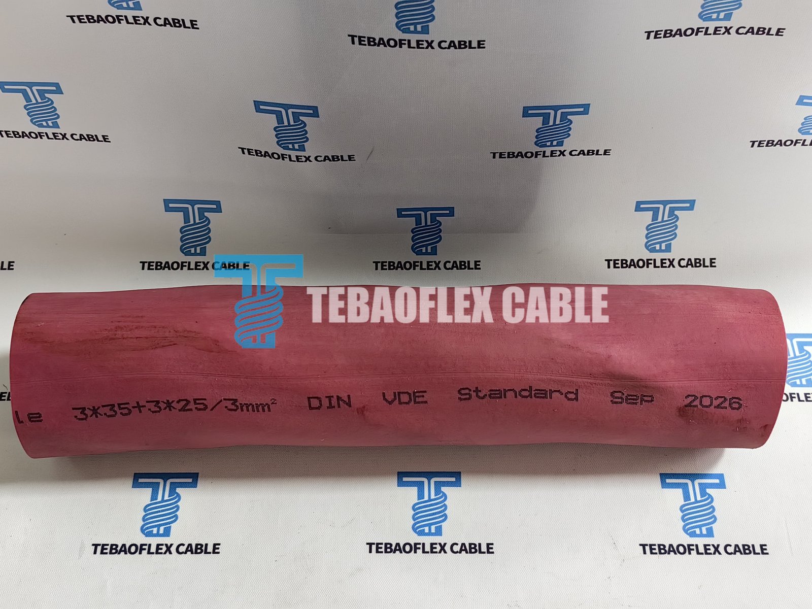
The supplied project information describes a Class 5 flexible tinned-copper conductor system, EPR insulation, semi-conductive layers, individual copper screening and a heavy-duty rubber sheath. The construction is intended to combine flexible power transmission with electrical field control and mechanical protection. Exact material grades, dimensions and tolerances remain governed by the approved project drawing and final technical data sheet.
| Cable element | Project construction | Function |
|---|---|---|
| Power conductors | Flexible stranded tinned copper | Provides a flexible current path for moving duty |
| Conductor screen | Semi-conductive layer | Supports controlled electrical stress at the conductor surface |
| Insulation | EPR rubber compound | Provides the primary 12/20 kV insulation system |
| Insulation screen | Semi-conductive layer | Controls the electrical field around each insulated core |
| Metallic screen | Individual copper wire screen or braid | Provides the specified screened-core arrangement |
| Core assembly | Three power cores with divided conductors and rubber filling | Maintains the project-specific round flexible construction |
| Inner sheath | EPR-based rubber compound | Provides bedding and protection for the assembled cores |
| Outer sheath | Heavy-duty rubber compound | Protects the cable during handling and the agreed mining duty |
DIN VDE 0250-813 is the relevant standard listing for trailing cables in this project documentation. The conductor requirements also refer to IEC 60228, which covers nominal conductor cross-sections, conductor classes and resistance requirements. The applicable editions and contractual test criteria must be stated in the signed purchase specification; a general website description does not replace those documents.
How the three power cores are identified during installation
The customer’s installation team asked how the three 35 mm² power cores could be distinguished when connecting the excavator and transformer. The agreed production method was to mark the insulation of the three power cores with the numbers 1, 2 and 3. This gives the installer a repeatable reference at both cable ends and reduces the risk of relying on position alone after the cores have been laid up.
Core numbering is only one part of the termination procedure. Before energisation, the installation team should verify phase identification from end to end, continuity, screen and protective-conductor connections, termination dimensions, stress-control components and the manufacturer’s installation instructions. Final phasing remains the responsibility of the authorised electrical team at the site.
Dimensional inspection before release
Medium-voltage performance depends on more than the finished outer diameter. Insulation thickness, insulation-screen thickness and the condition of the prepared interface affect the electrical field within the cable. The inspection plan therefore included dimensional measurements on prepared samples rather than checking only the external appearance.
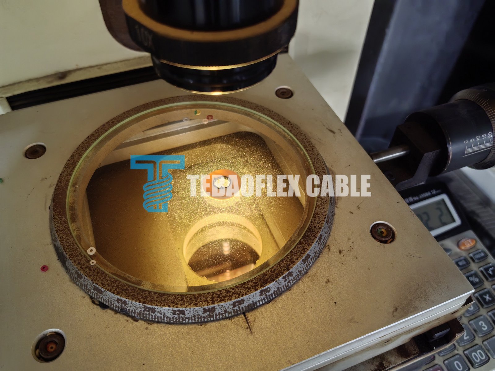
The photographs document the inspection process, but they are not substitutes for a signed Factory Test Report. The final report should identify the reel or production length, measuring instrument, test date, applicable procedure and actual recorded result. This distinction is important because a photograph of a gauge or display does not show the full measurement sequence, calibration status or acceptance limit.
Factory acceptance tests requested for every reel
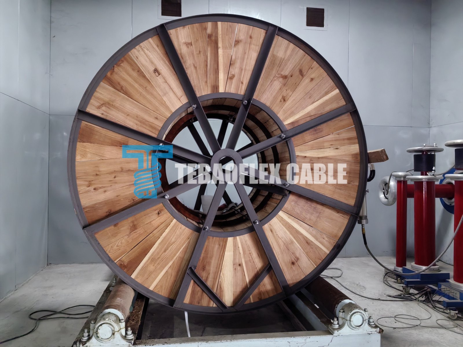
The customer asked for the range of tests and inspections to be confirmed before each production length or reel left the factory. The project discussion also required a final Factory Test Report and a Declaration of Conformity as part of the delivery documentation. This made traceability and actual measurement records part of the product deliverable.
| Inspection or test | Purpose | Required record |
|---|---|---|
| Visual and marking inspection | Confirm sheath condition, cable identity and production marking | Reel or length reference and inspection result |
| Conductor and divided-conductor resistance | Verify the electrical conductor construction | Measured value corrected to 20°C where required |
| Whole-length continuity | Confirm every conductor remains electrically continuous | Result for each power and divided conductor |
| Insulation resistance | Evaluate insulation integrity under the approved procedure | Test voltage, temperature, length and measured result |
| Dimensional inspection | Verify insulation, screen and finished cable dimensions | Actual measured dimensions and tolerances |
| AC withstand test | Check the completed insulation system | The project plan listed 29 kV for 5 minutes; final criteria follow the approved test plan |
| Partial-discharge measurement | Evaluate discharge behaviour of the MV insulation system | Test arrangement, voltage points and signed results |
| Screen inspection | Confirm the specified metallic screen construction and continuity | Inspection and electrical records as applicable |
The buyer’s requirement for each reel matters. A type test or sample result from another production batch does not by itself verify the delivered length. TEBAOFLEX’s certification and test-document support is used to organise the agreed records, but the final acceptance package must correspond to the actual project cable.
How continuity and conductor material were checked
The customer also wanted assurance that the conductors were complete over the manufactured length and that the specified tinned-copper construction had been used. The factory response combined whole-length electrical continuity checks, conductor-resistance measurements, production tracking and visual inspection of stripped samples.
Visual colour can help distinguish tinned strands from bare copper, but appearance alone is not an acceptance method. Resistance values, conductor construction records and the approved material specification provide stronger evidence. Similarly, a multimeter continuity check confirms an electrical path but does not replace the complete set of resistance, insulation, high-voltage and partial-discharge tests required for a screened 12/20 kV cable.
What this project demonstrates for mining cable buyers
The main lesson is that a model designation is not enough to approve a mining cable. The electrical system, reel mechanics, movement pattern, environment, termination design and acceptance documents must be reviewed together. For this Polish excavator project, the cable configuration was linked to a defined 12/20 kV duty, numbered power-core identification and a reel-by-reel inspection plan.
- Confirm the machine: provide the excavator type, reel drawing, travel distance and cable route.
- Confirm the electrical duty: provide voltage, load data, conductor arrangement, fault requirements and grounding method.
- Confirm the movement: provide reeling speed, acceleration, duty cycle, bend direction, number of layers and maximum tension.
- Confirm the environment: state temperature limits and exposure to water, oil, abrasion, sunlight, dust or chemicals.
- Confirm the acceptance plan: define standards, test voltages, partial-discharge criteria, inspection hold points and required reports before production.
- Confirm the interfaces: provide termination, gland, connector and transformer-entry details.
The wider mining and tunnelling cable range includes constructions for different voltage classes and movement duties. Similar-looking cables should not be treated as interchangeable without a technical review. Factory testing and production capabilities can also be viewed on the cable factory and testing videos page.
Information to send for a similar project
For a new mining excavator, stacker, reclaimer or mobile transformer connection, send the voltage, conductor size, required length, reel dimensions, minimum bend radius, reeling speed, pulling force, environmental limits and requested test plan. Photographs and equipment drawings help the engineering team understand the complete route. If the final model has not been selected, start with the operating conditions rather than choosing a cable name from a catalogue.
TEBAOFLEX can review those inputs through its custom cable engineering and export support process. Available catalogue starting points are listed in the industrial cable product range, while the approved construction, manufacturing data and FAT programme are prepared against the specific order.
Project conclusion
This project converted a demanding mining-machine requirement into a defined 12/20 kV (N)TSCGECEWOEU cable configuration and a documented pre-shipment inspection plan. The evidence covered cable construction, sheath marking, core identification, dimensional inspection, whole-length continuity, resistance, insulation, high-voltage and partial-discharge checks. That process gives the customer a clearer technical basis for approving the delivered reel before installation.
To discuss a comparable medium-voltage reeling cable, send your machine drawing, voltage, cable length, conductor configuration, movement data and FAT requirements through the TEBAOFLEX contact form. The engineering team will review the application boundaries and prepare a project-specific proposal for technical confirmation.