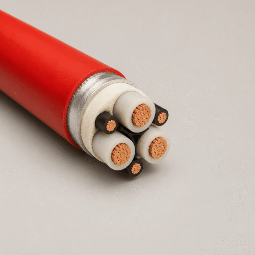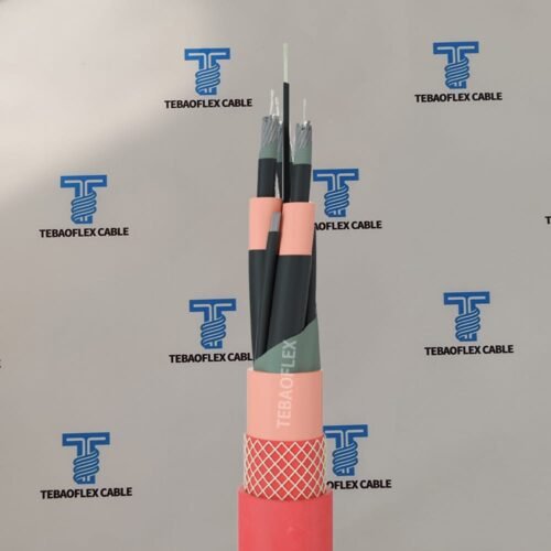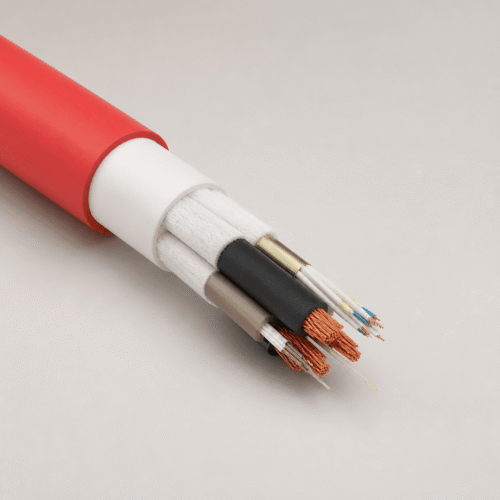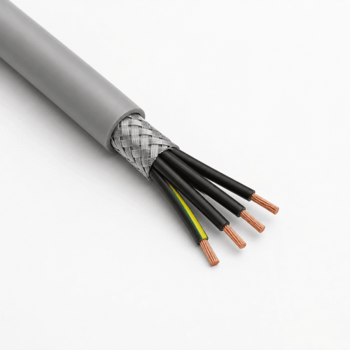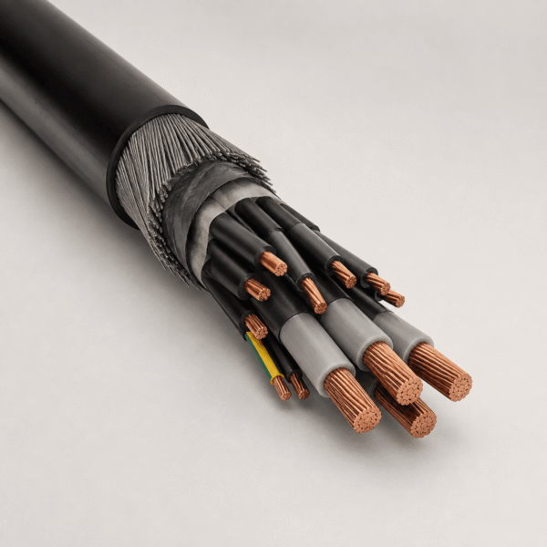




(N)3GHSSYCY 3.6/6 kV (available up to 6/10 kV, 8.7/15 kV, and 12/20 kV) is a screened, steel-wire-braid armoured medium-voltage mining power cable engineered in reference to DIN VDE 0250-605 and IEC 60502-2. Unlike rigid Class 2 SWA distribution cables, it combines Class 5 flexible copper conductors and EPR 3GI3 rubber insulation with individual copper screens and a flexible galvanized steel-wire braid, enabling safe installation along curved underground mine drifts, inclined shafts, TBM tunnel walls, and relocatable substation skids.
1. Application Scope & Underground Duty Selection
Underground hard-rock mines, coal galleries, and tunnel-boring projects require medium-voltage feeder cables that combine earth-fault electrical screening, high mechanical rockfall protection, and enough flexibility to pull around tight gallery turns without crane-reel bulk. (N)3GHSSYCY serves fixed and semi-mobile MV distribution routes:
- Underground Mine Galleries & Inclined Drifts: Wall-cleated or tray-mounted MV distribution feeders linking shaft-bottom switchgear to advancing mining districts in underground mining and tunnelling power networks.
- Relocatable Skid Substations & TBM Backup Gantries: Semi-mobile MV feeders periodically shifted as longwall panels, roadheaders, or tunnel-boring machines advance.
- Vertical & Inclined Shaft Suspensions: Self-supporting shaft drops where galvanized steel-wire braid armour bears calculated vertical suspension loads when anchored in proper armour cone clamps.
Where continuous dynamic drum reeling or open-pit shovel trailing is required instead of armoured gallery routing, specify our unarmoured rubber (N)TSCGEWÖU MV trailing and reeling cable. For single-core cabinet jumpers inside mine substations, see (N)TMCGCW11Y single-core MV PUR cable or browse all mining and tunnelling cables.
Installation & Termination Boundary: (N)3GHSSYCY is NOT a high-speed drum-reeling cable; repeated spooling under tension will fatigue the galvanized steel-wire braid and PVC sheaths. Always select MV glands equipped with an armour clamping ring for the steel braid and confirm your mine earth-fault relay’s required pilot/earth screen cross-section before ordering.
2. Cable Construction (DIN VDE 0250-605 Layer Breakdown)
From conductor to outer sheath, each letter of (N)3GHSSYCY corresponds to a physical protection layer verified on the project cross-section drawing:
+90°C) + outer semi-conductive insulation screen (code 3GH).3 + 3 (3 MV phase + 3 interstitial pilot/split-earth cores) or project-configured 3 + 3 + 3 arrangement around a shaped elastomer centre cradle.≥3.6/6 kV MV mine identification per VDE) or black; oil- and abrasion-resistant.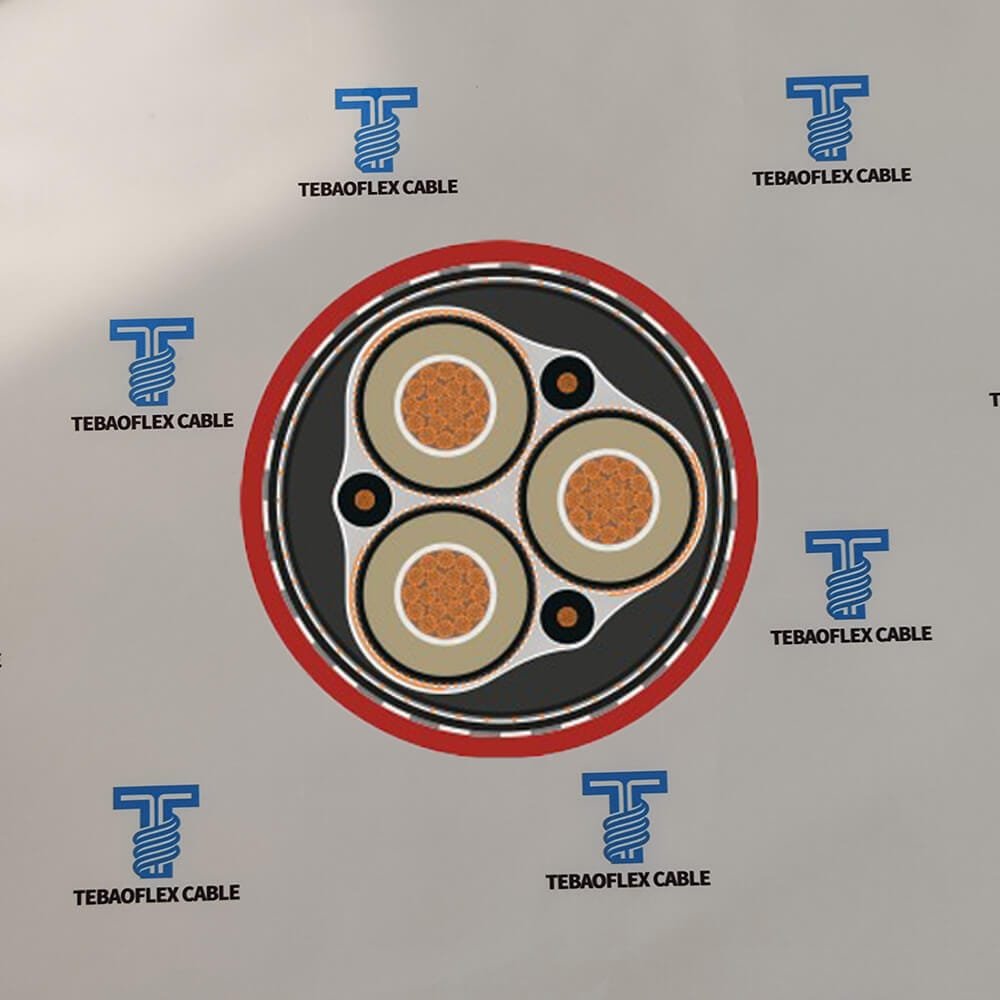
3. Technical Characteristics
Electrical, thermal, and mechanical installation ratings for (N)3GHSSYCY armoured mining feeders are summarized below:
| Parameter | Specified Engineering Value |
|---|---|
| Design References | DIN VDE 0250-605; dielectric & voltage testing referenced to IEC 60502-2 |
| Voltage Classes U0/U (Max Um) | 3.6/6 kV (7.2 kV), 6/10 kV (12 kV), 8.7/15 kV (17.5 kV), 12/20 kV (24 kV) |
| Routine AC Test Voltage (5 min) | 11 kV (3.6/6 kV) / 17 kV (6/10 kV) / 24 kV (8.7/15 kV) / 29 kV (12/20 kV) |
| Max Conductor Temperature | +90°C continuous normal operation; +250°C max short-circuit (up to 5 s) |
| Ambient Temperature Range | Fixed gallery / shaft routing: -20°C to +70°C; flexing during installation / relocation: -5°C to +70°C |
| Minimum Bending Radius | Fixed installed position: 10 × D; pulling / relocation bending: 15 × D (DIN VDE 0298-3) |
| Flame Retardance | Self-extinguishing to IEC 60332-1-2; bunched gallery flame test IEC 60332-3-24 available on request |
| Outer Jacket Colour Convention | Signal Red (standard German VDE underground MV warning colour) or Black for industrial tunnels |
4. Voltage Classes & Representative 3.6/6 kV – 6/10 kV Specification Table
Documented conductor cross-section availability across all four MV ratings and representative 3.6/6 kV and 6/10 kV reference dimensions are listed below:
| Voltage Rating (U0/U) | Available Phase Sizes (mm²) | Representative Core Schedule | Approx. Outer Diameter (mm) | Approx. Copper Weight (kg/km) | Approx. Total Weight (kg/km) |
|---|---|---|---|---|---|
| 3.6/6 kV | 25 mm² | 3 × 25 + 3 × 16/3 (or pilot) | 41.5 – 44.5 | 1,090 | 2,950 |
| 3.6/6 kV | 35 mm² | 3 × 35 + 3 × 16/3 | 44.0 – 47.0 | 1,380 | 3,420 |
| 3.6/6 kV | 50 mm² | 3 × 50 + 3 × 25/3 | 48.0 – 51.5 | 1,920 | 4,180 |
| 3.6/6 kV | 70 mm² | 3 × 70 + 3 × 35/3 | 52.5 – 56.0 | 2,590 | 5,150 |
| 3.6/6 kV | 95 mm² | 3 × 95 + 3 × 50/3 | 57.5 – 61.5 | 3,460 | 6,380 |
| 3.6/6 kV | 120 mm² | 3 × 120 + 3 × 70/3 | 61.5 – 65.5 | 4,360 | 7,560 |
| 3.6/6 kV | 150 mm² | 3 × 150 + 3 × 70/3 | 66.0 – 70.5 | 5,230 | 8,820 |
| 3.6/6 kV | 185 mm² | 3 × 185 + 3 × 95/3 | 70.5 – 75.5 | 6,480 | 10,450 |
| 6/10 kV | 25 – 185 mm² | 3×25, 35, 50, 70, 95, 120, 150, 185 | 43.5 – 78.0 | 1,120 – 6,550 | 3,150 – 10,950 |
| 8.7/15 kV | 25 – 120 mm² | 3×25, 35, 50, 70, 95, 120 | 48.0 – 71.0 | 1,160 – 4,480 | 3,550 – 8,400 |
| 12/20 kV | 25 – 185 mm² | 3×25, 35, 50, 70, 95, 120, 150, 185 | 52.0 – 85.0 | 1,210 – 6,720 | 3,950 – 12,300 |
Exact outer diameters and weights vary with individual phase-screen copper cross-section, 3+3 vs 3+3+3 pilot/PE configuration, and shaft-tensile steel-braid wire gauge—request a confirmed production drawing prior to ordering MV glands or cleats.
5. Frequently Asked Engineering Questions
What does each letter in the German mining code (N)3GHSSYCY signify?
Under DIN VDE 0250-605 nomenclature, (N) indicates construction adapted to the German VDE standard, 3G denotes heat-resistant EPR rubber insulation Type 3GI3 (+90°C), H specifies semi-conductive field-control layers, SS denotes individual concentric copper screens over the main/pilot cores, the first Y is the PVC inner sheath, C is the galvanized steel-wire braid armour, and the final Y is the heavy-duty flame-retardant PVC outer sheath.
Why use Class 5 flexible conductors inside a steel-wire-armoured cable?
Conventional Class 2 SWA power cables are stiff and difficult to pull around tight underground drift turns, TBM backup gantries, or relocatable mine transformer skids. Pairing Class 5 flexible copper and EPR 3GI3 rubber cores with a braided (rather than rigid single-wire) galvanized steel armour lets (N)3GHSSYCY absorb rockfall impact while still routing cleanly along curved tunnel walls and semi-mobile skids.
When should I choose (N)3GHSSYCY instead of (N)TSCGEWÖU?
Choose (N)3GHSSYCY for fixed, semi-mobile, inclined-gallery, TBM wall-hung, and vertical shaft feeder routes where rockfall impact resistance, braided steel tensile support, and bundled flame retardance (PVC YM5) are primary. Choose unarmoured rubber-sheathed (N)TSCGEWÖU whenever the cable must wind continuously on a motorized reel or drag dynamically behind an excavator or shovel.
What is the difference between 3+3 and 3+3+3 core arrangements in (N)3GHSSYCY?
In standard 3+3 underground gallery builds, the 3 screened MV phase cores carry 3 interstitial pilot/monitoring or split-earth cores in the outer valleys while phase copper screens + armour provide earth-fault capacity. In 3+3+3 project configurations, dedicated split protective-earth cores and separate pilot/control cores are both incorporated inside the core lay—always confirm your exact mine protection relay schematic on the order drawing.
Is (N)3GHSSYCY available above 3.6/6 kV?
Yes. Alongside 3.6/6 kV (25–185 mm²), TEBAOFLEX manufactures (N)3GHSSYCY in 6/10 kV (25–185 mm²), 8.7/15 kV (25–120 mm²), and 12/20 kV (25–185 mm²) voltage classes with scaled EPR 3GI3 wall thicknesses and AC routine test voltages.
What project details are required to quote (N)3GHSSYCY?
Send the rated voltage (3.6/6 kV up to 12/20 kV), phase conductor size (25 to 185 mm²), required earth-screen and interstitial pilot/PE schedule (3+3 or 3+3+3), outer sheath colour (signal red for MV warning or black), installation method (horizontal gallery cleats, TBM advance, or vertical shaft suspension height), and drum cut lengths.
Request (N)3GHSSYCY Armoured MV Mining Cable Drawing & Quote
Send your voltage class (3.6/6 kV to 12/20 kV), phase/pilot schedule, shaft or gallery installation profile, and drum lengths for factory engineering confirmation within 24 hours.