Why Cable Installation Matters
Proper cable installation is essential for safety, reliability, and maximizing cable service life. Even the highest quality cable can fail prematurely if installed incorrectly. Poor installation practices cause insulation damage, excessive mechanical stress, water ingress, and fire hazards — leading to unplanned downtime, costly repairs, and safety incidents.
This cable installation best practices guide covers the key principles and procedures for industrial cable installation, from pre-installation planning to post-installation testing. TEBAOFLEX cables are designed for reliable performance when installed correctly per these guidelines.
Pre-Installation Planning and Preparation
Review Specifications and Drawings
- Verify cable types, sizes, and quantities against project specifications and cable schedules
- Review cable routing drawings, tray layouts, conduit runs, and penetration details
- Confirm cable schedule includes voltage rating, insulation type, armor, shielding, and fire performance requirements
- Identify special requirements: explosion-proof areas, EMC/EMI zones, fire barriers, seismic considerations
Cable Handling and Storage
- Store cables in a dry, covered area. Protect cable drums from direct sunlight and weather.
- Store drums on their flanges (on edge), not flat. Flat storage can cause conductor deformation and jacket damage.
- Rotate drums periodically to prevent lubricant migration and flattening.
- Keep cable ends sealed with end caps or tape to prevent moisture ingress, especially for MV cables.
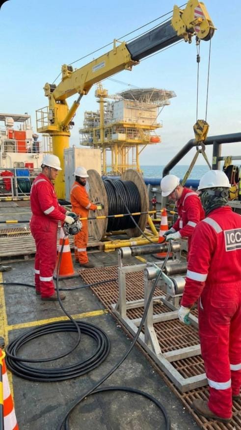
- Handle drums with proper equipment (forklift, drum jacks, crane). Never drop or roll drums over long distances.
- Check cable drum labels for type, size, length, and voltage rating before installation.
Tools and Equipment
- Cable drum stands / jacks with appropriate load capacity
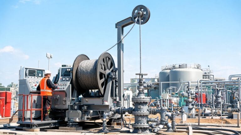
- Cable pulling equipment: winches, pullers, grips (wire mesh socks), swivels
- Force measuring device (tensiometer) to monitor pulling tension
- Cable rollers and guides (especially for bends and long pulls)
- Cutting tools: cable cutters, hacksaws, rotary cutters
- Stripping tools for insulation, sheath, and armor
- Crimping tools and dies for connectors and lugs
- Test equipment: multimeter, insulation resistance tester (Megger), hi-pot tester
Cable Pulling and Installation
Pulling Tension Limits
Exceeding the maximum pulling tension is one of the most common causes of cable damage during installation.
- LV power cables (Class 2 conductor): Typically 40-60 N/mm² of conductor cross-section for copper, 25-30 N/mm² for aluminum
- MV cables: Lower limits, often 20-30 N/mm² for copper. Consult manufacturer data.
- Control cables: Lower tension limits, especially for small sizes
- Flexible / reeling cables: Handle by hand whenever possible. Do not pull with grips.
Always use a tension meter or calculated pulling force based on cable weight, coefficient of friction, and route geometry. The pulling force should be applied to the conductor (using a pulling grip on the conductor) rather than the jacket, where possible.
Minimum Bending Radius
Bending cables tighter than their minimum bending radius causes internal damage to insulation, shielding, and armor. Minimum bending radii (multiplied by overall cable diameter D):
- Unarmored LV cables: 6D to 10D during installation, 4D to 6D fixed
- Armored cables (SWA/STA): 12D to 15D during installation, 8D to 10D fixed
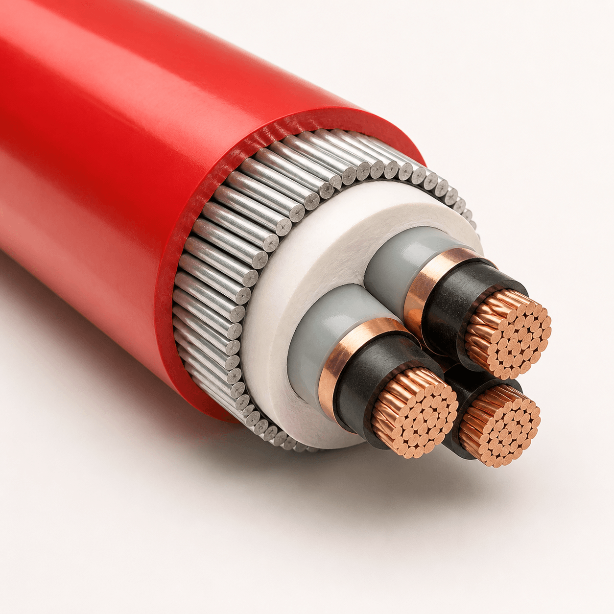
- MV cables: 15D to 20D for single-core, 12D to 15D for multi-core
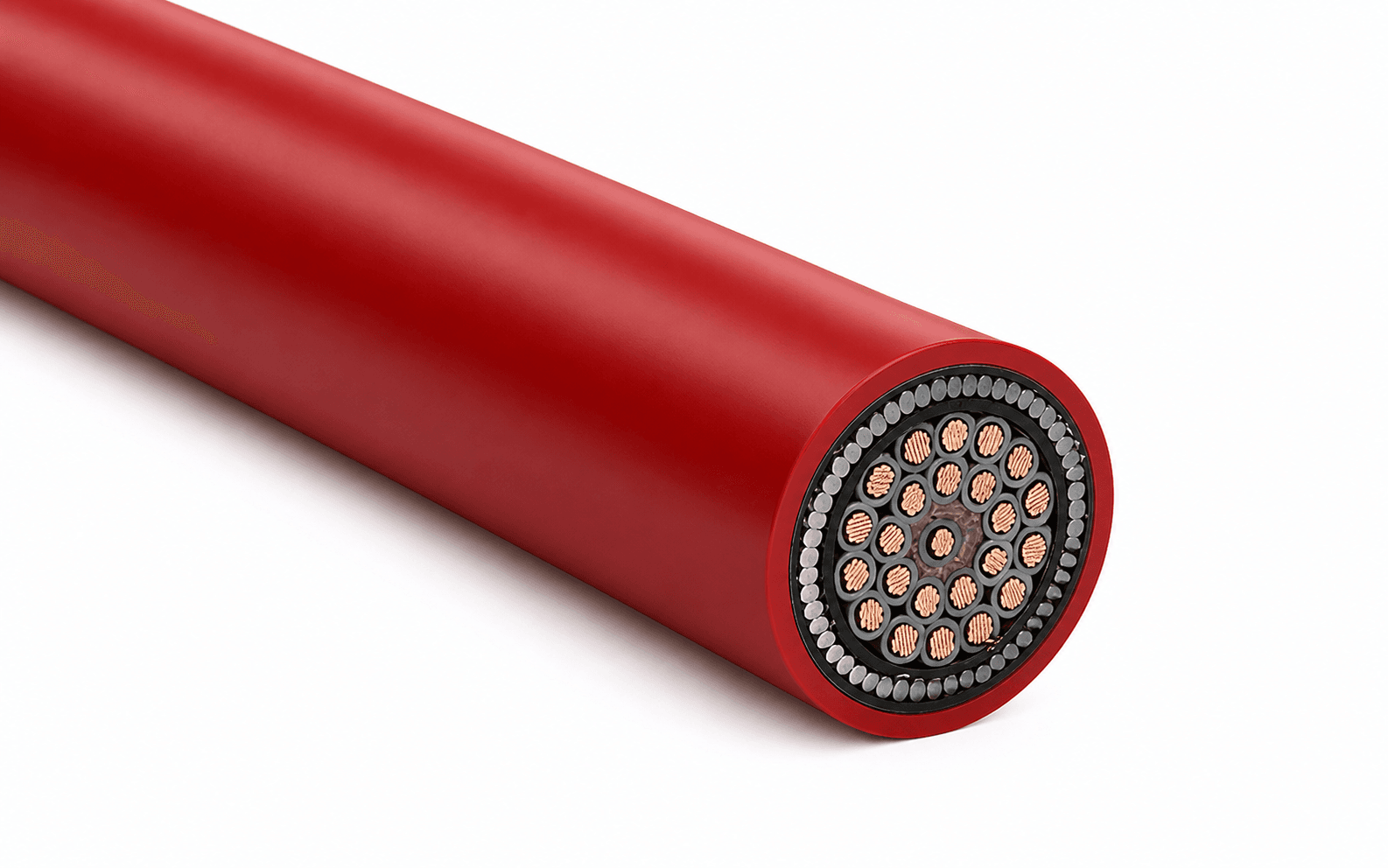
- Control/instrumentation cables: 6D to 10D
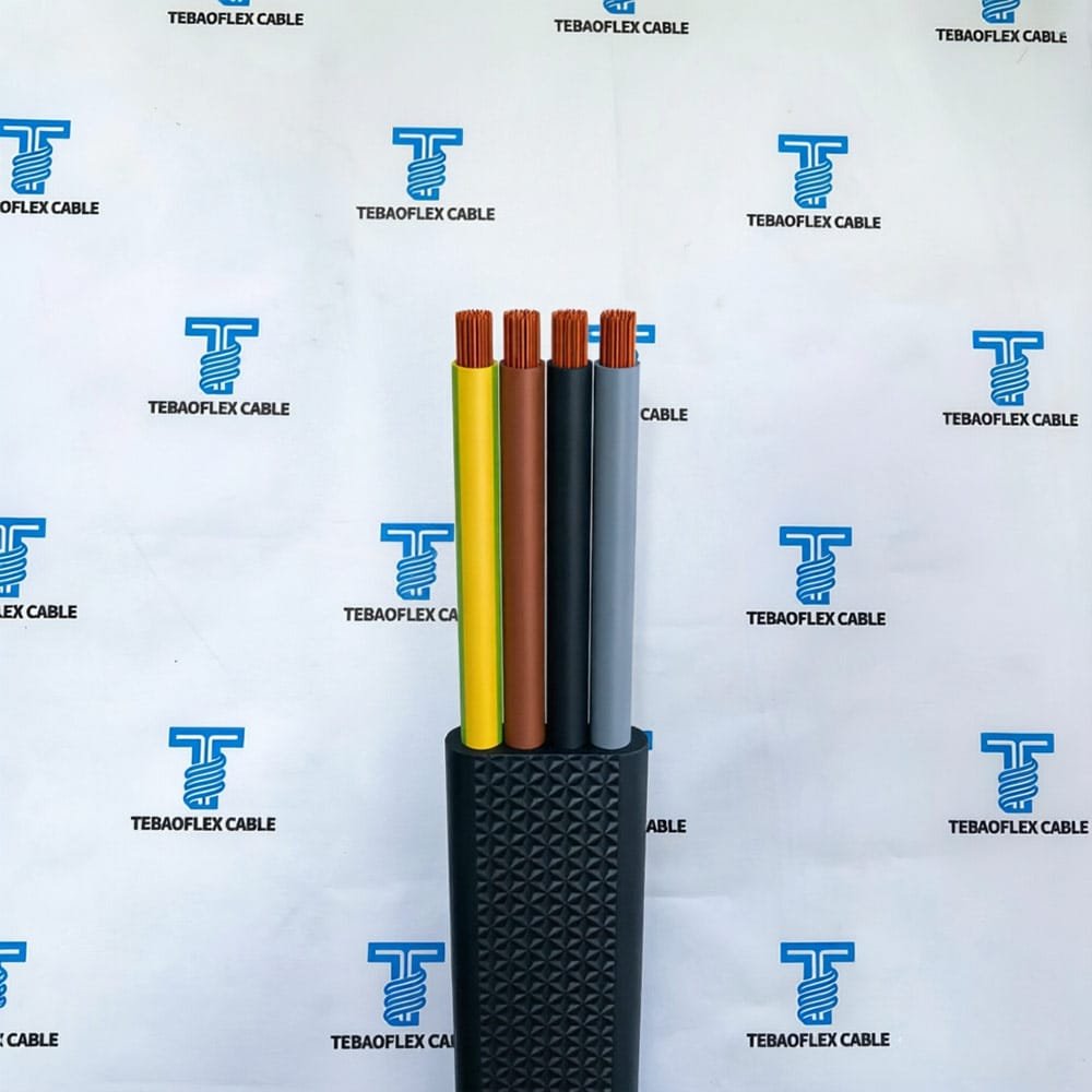
- Flexible cables: 5D to 8D (varies by conductor class)
Always consult the cable manufacturer’s installation instructions for specific bending radius values.
Cable Routing and Separation
- Route cables to minimize bends, especially tight bends. Use gradual bends where possible.
- Separate power cables from control/instrumentation cables to prevent electromagnetic interference (EMI). Maintain minimum separation distances per project specifications (typically 150-300mm).
- Where power and control cables must cross, cross at 90 degrees to minimize inductive coupling.
- Separate LV and MV cables by a minimum distance or by a grounded metal barrier.
- Avoid routing cables near heat sources. If unavoidable, use heat shields or select higher temperature-rated cables.
- Do not install cables where they will be subject to mechanical damage from moving equipment, vehicles, or falling objects.
- Use appropriate cable supports at maximum spacing intervals: vertical runs every 1-2m, horizontal runs every 0.5-1.5m depending on cable weight.
Cable Glands and Seals
- Select cable glands rated for the cable type, size, and environmental protection rating (IP rating).
- Ensure correct gland thread size and entry thread type (NPT, PG, metric).
- For armored cables, use glands with appropriate armor clamping. Ensure the armor makes good electrical contact for grounding/bonding.
- For shielded/screened cables, use glands that provide 360-degree shield termination for EMC performance.
- Use appropriate sealing (compound, grommet, O-ring) to maintain ingress protection.
- Seal all wall and floor penetrations with fire-rated sealants to maintain fire resistance ratings.
Conduit and Tray Installation
Cable Tray Best Practices
- Install cable tray to maintain adequate support and allow future cable additions.
- Do not exceed the cable tray load rating. Distribute cables evenly across the tray width.
- Maintain cable fill ratio: typically 40-50% for power cables, 30-40% for control/instrumentation cables to allow heat dissipation.
- Use horizontal separators to segregate different voltage levels or circuit types within the same tray.
- Bond and ground cable tray systems per applicable electrical codes.
- Install expansion joints in long tray runs to accommodate thermal expansion.
Conduit Installation
- Size conduit properly: wire fill must not exceed code limits. NEC Chapter 9 Table 4 and 5 provide fill percentages.
- Use sweeping bends rather than multiple tight bends. Limit the number of bends between pull points (typically no more than 360 degrees total).
- Install pull boxes at appropriate intervals for long runs and at direction changes.
- Ensure conduit ends are deburred and reamed to prevent cable jacket damage during pulling.
- Use appropriate lubricants for cable pulling — use only lubricants compatible with the cable jacket material.
- Seal conduit entries to enclosures and equipment to maintain IP ratings.
MV Cable Termination and Jointing
Medium voltage cable terminations and joints are critical points — most MV cable failures occur at these locations.
- Qualified personnel only: MV cable joints and terminations must be installed by trained, certified technicians.
- Use manufacturer-approved kits: Use only termination and joint kits specified or approved by the cable manufacturer.
- Clean environment: Prepare terminations in a clean, dry environment. Use a clean tent or shelter for field installations.
- Follow instructions exactly: Adhere strictly to the kit manufacturer’s step-by-step instructions. Dimensional accuracy is critical.
- Stress control: Properly install stress cones or stress control tubes at the insulation shield cut-back point.
- Insulation resistance test: Test before and after installation to detect any damage.
- Partial discharge test: Recommended for MV cable systems to detect insulation defects.
Post-Installation Testing
Testing after installation verifies the cable was not damaged during installation and confirms correct connections:
- Continuity test: Verify each conductor is continuous and correctly identified. Check for open circuits and cross-connections.
- Insulation resistance test (Megger): Test between conductors and between each conductor and ground/armor. Minimum values vary by voltage rating and standard. Compare with manufacturer’s data and previous readings.
- DC hi-pot test (HV test): Apply DC voltage above rated voltage for a specified time. Used to detect insulation defects. More common for MV/HV cables.
- VLF (Very Low Frequency) test: Alternative to DC hi-pot for XLPE/EPR cables. Considered less damaging to certain insulation types.
- Sheath/armor continuity and bonding test: Verify proper grounding and bonding of cable shields, sheaths, and armor.
- Phase identification: Confirm correct phase rotation and identification at both ends of the cable.
Record all test results and maintain documentation for future reference and trend analysis.
Safety Considerations
- Follow all applicable safety regulations, lockout/tagout (LOTO) procedures, and site safety rules.
- Wear appropriate PPE: safety glasses, gloves, hard hat, steel-toe boots, and other site-specific PPE.
- Ensure proper lifting techniques and equipment for heavy cable drums.
- Use fall protection when working at height (ladders, elevated cable trays).
- Verify circuits are de-energized and locked out before working on cables.
- Cap and insulate exposed conductors, even on circuits believed to be de-energized.
- Maintain proper ventilation in confined spaces. Test atmosphere before entry.
- Have appropriate fire extinguishing equipment available, especially when working with MV/HV cables.
Documentation and As-Built Records
- Maintain complete as-built cable schedules showing cable number, type, size, route, length, and termination points
- Record all test results in a cable test report
- Label cables at both ends and at intermediate points (junction boxes, pull boxes) with cable identification tags
- Keep manufacturer data sheets, test certificates, and installation instructions on file
- Photograph key installation details (particularly hidden work) for future reference
- Update drawings and documentation to reflect any field changes or deviations
TEBAOFLEX Technical Support
TEBAOFLEX provides comprehensive installation support for our cable products:
- Detailed installation instructions and technical datasheets for each cable type
- Pulling tension and bending radius calculations for specific cables
- Technical support for termination and jointing procedures
- On-site technical assistance for critical installations (by arrangement)
- Training for installation teams and electrical contractors
Need technical support for your cable installation project? Contact TEBAOFLEX engineering for expert guidance and recommendations.
Request a Quote
Looking for high-quality industrial cables backed by expert technical support? TEBAOFLEX manufactures a full range of LV, MV, control, instrumentation, and specialty cables. Submit your project requirements for a competitive quotation and technical proposal.